Note: Descriptions are shown in the official language in which they were submitted.
2 ~
TITLE OF THE INVENTION
CONNECTOR
BACKGROUND OF THE INVENTION
1. Field of the Invention
This invention relates to a connector having a moving
plate adapted to form a contacting state and a non-contacting
s-tate in a connector body.
2. Brief Description of the Prior Art
A conventional connector known to the art aims at no-
load insertion and removal of an IC package to and from an IC
socket and includes a movable plate mounted on a connector
body, and an operating lever for operating a lateral movement
of the movable plate, so that a contacting state and a
releasing state can be formed by the lateral movement of the
movable plate.
By mèans of operation for pushin~ down the operating
lever, the movable plate is laterally moved in one direction
along the upper surface of the connector body. The lateral
movement of the movable plate causes the contacts of the con
nector body to be displaced to a closed state, thereby form-
ing a contact-releasing state relative to the IC leads of an
IC package placed on the movable plate so that no-load inser-
tion of the IC package to the IC socXet can be obtained. On
~ J ~ `3 ~
the other hand, by means of operation for releasing the push-
ing down, the movable plate is urged by restoring force of
the contacts and laterally moved in the opposite direction,
thereby forming a contacting state relative to the IC leads.
In recent years, a robot was used in many cases for
operation the operating lever in order to enhance workability
and to save energy. Therefore, the operating lever is
required to have such a construction as that the operating
lever can easily be pushed down by means of a vertical move-
ment of a robot.
However, the conventional connector has the following
problems. That is, a lever is used as means (operating
lever) for moving the movable plate in the lateral direction
with a small amount of force. However, the movement of a
lever is a pivotal movement, while the movement of a robo-t is
a vertical movement. Since the moving directions are dif-
ferent, the pushing down position of the lever is limited and
as a result, the robot is difficult to be operated effec-
tively. Moreover, where a plurality of operating levers
are ~rovided to the connector body, these levers must be in-
dividually pushed down at the same timing.
The above-mentioned problems also arise where an operat-
ing lever or levers are manual 1Y operated.
Furthermore, in the above-mentioned prior art, when the
contacts are displaced by the reciprocal movement of the mov-
3 2
able plate, an electric part moun-ted on the movable plate is
also moved following the movement of the movable plate and
therefore, the mounting position of the electric part is
changed.
In recent years, since the operation for removing an
electric part, especially an IC package, is made by an
automation device such as a robot or the like, an accessing
position of the automation device is changed if the mounting
position is changed. As a result, there occurs a failure
in removal of the electric part and mail terminals are
deformed because the electric part is removed in its inclined
state. Moreover, the change of the mounting position causes
the contacting position and the contact-releasing position
between the male terminals and contacts to become unstable.
As a result, reliability of the contacting relation is badly
jeopardized.
The present invention has been accomplished in order to
overcome the above-mentioned problems inherent in the prior
art.
SUMMARY OF THE INYENTION
It is therefore a first object of the present invention
to provide a connector which can easily cope with automation
requirement using a robot.
A second object of the present invention is to provide a
connector including a ~ovable plate for displacing contacts,
in which the mounting position of an elec-tric par~ re~ative
to a connector body is always held in a predetermined posi-
tion so that the mounting and removing operation of the
electric part can be properly carried out by an automation
device and at the same time, the contacting position and the
contact-releasing position of the electric part relative to
the connector can be obtained properly.
In order to achieve the above objects, there is essen-
tially provided a connector including a connector body, a
movable plate mounted to said connector body, an operating
lever, a contacting state and a contact-releasing state being
formed by a lateral movement of said movable plate, said con-
nector comprising an upper part operating member disposed
above said operating lever for movement upward and downward,
and a pressure bearing portion formed on one end portion of
said operating lever and adapted to carry said upper part
operating member, pushing down operation of said upper part
operating member causing said pressure bearing portion to be
pushed down to move said movable plate in a lateral direc-
tion.
According to the connector of the present invention, the
operating lever can be pushed down by vertically pushing down
the upper part operating member following the vertical motion
of a robot. The contacting position between a manipulator
of the robot and the upper part operating member is held in a
predeterm;ned position and the pushing down operation is per-
formed in that state. Moreover, an operating position for
the robot is secured by the upper part operating member, thus
enabling to cope with automation requirement using a robot
properly.
~ urthermore, manual operation can also be performed with
ease. For example, where a plurality of operating levers
are provided, all of these operating levers can be pushed
down at the same timing by the upper part operating member
to move the movable plate properly in the lateral direction.
From another aspect of the invention, there is essen-
tially provided, in order to achieve the above objects, a
socket comprising a connector body which is held in a sta-
tionary state when mounted on a wiring board, etc., a guide
erected from said connector body in such a manner as to be
projected upward of a movable plate along the side edge por-
tion of a reciprocal motion of said movable plate, said guide
regulating both end faces of an electric part at a portion
projecting upward of said movable plate, in order to prevent
the electric part from following the reciprocal movement of
the movable plate and to maintain a relative position.
From still another aspect of the invention, there is es-
sentially provided a soc~et comprising a connector body, a
first guide erected from the connector body, a movable plate
and a second guide erected from said movable plate, a loading
position of an electric part being esta~lished by said first
and second guides.
According to the above-mentioned invention, the guide is
erected from the connector body in such a manner as to be
projected upward of the movable plate exceeding one end
thereof~ and an electric part is regulated at both end faces
thereof by the projecting part of -the guide so that the
electric part can be loaded in a predetermined position.
Furthermore, when the movable plate is reciprocally
moved in order to displace the contacts into a contact-
releasing state, the projecting part of the guide erected
rom one end of the connector bod~ prevents the electric part
from moving toward one direction following the movement of
the movable plate and the projecting part of the guide
erected from the other en~ of the connector body prevents the
electric part from moving toward the other direction follow-
ing the movement of the movable plate, thereby maintaining
the pred~termined loading position of the electric part.
As a result, the position of the electric part relative
to the connector body is normally held constant and not fluc-
tuated even if the movable plate is moved. Accordingly,
there can be obviated such problems as that the electric part
is incorrectly taken out or loaded by an automation device,
and the male terminals are deformed when the electric part is
removed by an automation device.
On the other hand, the movable plate is assured an inde-
pendent movement for operatin~ to displace th'e contacts, and
a contacting relation and a contact-releasing relation be-
tween the male terminals and the contacts can properly be ob-
tained.
Furthermore, by erecting the first guide from the con-
nector body and the second guide from the moving plate, the
position of the electric part can more surely be established
and the reciprocal movement of the movable plate can properly
be performed while maintaining a relative position of the
electric part.
The above and other objects and features of the present
invention will be more manifest to those skilled in the art
upon reading the following detailed descrip-tion of the em-
~ bodiment with re~erence to the accompanying drawing.
BRIEF D_S RIPT]ON OF THE DRAWING
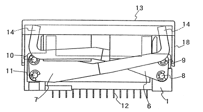
~; Fig. 1 is a perspective view showing one embodiment of a
connector according to the present invention;
Fig. 2 is a perspective view of an upper part operating
member disengaged from the connector of Fig. 1,
Fig. 3 is a side view of the connector before the upper
part operating member is pushed down;
Fig. 4 is a side view of the connector after the upper
part operating member is pushed down;
Fig. 5(A) is a sectional view of the connector in which
a movable plate is in a position for forming,closed state of
contacts, and Fig. 5(B) is a plan view showing a positional
relationship between an electric part and first and second
guides in Fig. 5(A);
Fig. 6~A) is a sectional view of -the connector in which
the movable plate is in a position for forming an opened
state of the contacts, and Fig. 6(B) is a plan view showing a
positional relationshiP between the electric part and the
first and second guides in Fig. 6(A); and
Fig. 7(A) is a sectional view of the connector in which
the movable plate is in a position for forming a state of
terminals clamped by the contacts, and Fig. 7(B) is a plan
view showing a positional relationship between the electric
part and the first and second guides in Fig. 7(A).
DETAILED DESC~IPTION OF THE EMBODIMENT
One embodiment of the present invention wiil be
described hereinafter with reference to Figs. 1 through 7.
The numeral 1 denotes a connector body monnted on a
wiring board or the like. The connector body 1 has a mov
able plate 2 which moves along the upper surface of the con-
nector body 1.
The movable plate 2 is superposed on the upper surface
of the connector body l. The movable plate 2 is provided
with a plurality of holes 5 for permitting a plurality of
male ~erminals ~ of an electric part 3 to~be penetrated
therethrough. While placing the electric part 3 on the up-
per surface of the movable plate 2, the male terminals ~ are
penetrated into the terminal penetration holes 5 and the tips
of the male terminals 4 are inserted into contact acco~moda-
tion chambers 1~ which are formed in the connector body I in
such a manner as to correspond to the terminal penetration
holes 5. On the other hand, contacts 12 are accommodated in
the contact accommodation chambers 15 of the connector body 1
and one csntact element of each of -the contacts 12 clamping
the male terminals 4 is engaged with the movable plate 2.
The lateral movement of the movable plate 2 toward the above-
mentioned one direction causes the contact element 12a to be
displaced against resiliencY thereof to bring each of the
contacts 12 into an opened state to close thereof. Also, by
applying a restoring force of the contact element 12a to the
movable plate 2, the movable plate 2 is laterally moved in
the other direction to bring each of the contacts 12 in a
closed state. No load insertion and removal of the electric
part 3 is performed in the above mentioned opened state of
each of the contacts 12, while each of the male terminals 4
are clamped in the closed state.
As means for performing the lateral movement operation
J~
of the movable plate 2, the connector of the present inven-
tion includes a first operating lever 6 and a second operat-
ing lever 7. A lower part of one end of the first operating
lever 6 is pivotably axially supported by a supporting shaft
8 at one end oE one side surface of the connector body 1, and
an upper part of the same end of the operating lever 6 is
axially supported by a transmission shaft 9 at one end of the
same side surface of the movable plate 2. On the other
hand, an upper part of one end of the second operating lever
7 is pivotably axially supported by a supporting shaEt 10 at
the other end of the same side surface of the connector body
1, and a lower part of the same end of the operating lever 7
is axially supported by a transmission shaft 11 at the other
end of the same side surface of the movable plate 2.
The arrangement being such that the transmission shafts
9 and 11 transmit a lateral force directing in one direction
to the movable plate 2 when the :Eirst and second operating
levers 6 and 7 are pivoted downward about the supporting
shafts 8 and 10 and transmit a lateral Eorce direction in the
other direction to the movable plate 2 when both of the first
and second operating levers 6 and 7 are pivoted upward.
Tha-t is, the upper and lower positional arrangement of
the supporting shaft 8 and the transmission shaft at one end
of the first operating lever 6 is in a reversed relation with
the upper and lower positional arrangement of the sup~orting
~1 $ f.~ r ~J
shaft 10 and the transmission shaft 11 at one end o-f the
second operating lever 7.
An upper part operating member 13 is vertically movablY
disposed above the first and second operating levers 6 and 7,
and the operating member 13 is horizontally carried by pres-
sure bearing portions 14 each formed on the first and second
operating levers 6 and 7.
The first and second operating levers 6 and 7 extend in
the opposite directions with respect to each other along the
side surface of the connector body 1. The first opera~ing
lever 6 is provided at its free end with the pressure bearing
portion 14 adapted to support one end of the upper part
operating member 13, while the second operating lever 7 is
provided at its ree end with the ~ressure bearing portion 1~
adapted to support the other end of the upper ~art operating
member 13. As one modified example, it may be designed such
that the first and second operating le~ers 6 and 7 are ar-
ranged in a symmetric relation with respec-t to each other on
both sides of the connector body 1, the ree ends of the
first and second operating levers 6 and 7 are connected
together above the movable plate 2, connection bars 6a and 7a
being served as the pressure bearing portions 14.
On the other hand, the upper part operating member 13
has an opening 16 corresPonding to the upper surface of the
movable plate 2 and exhibits a generally framework conigura-,
11
r~
tion as a whole. The electric part 3 is inserted and
removed through the opening 16. The upper part operating
member 13 is placed a framework element thereof and horizon-
tally carried on the pressure bearing portions 14 formed of
the connection bars 6a and 7a. The framework element 17
carried on the connection bar 6a forming the pressure bearing
portion 14 has a generally inverted L shape in section, and
the connectinn bars 6a and 7a are engaged with the inner side
of the generally inverted L shape of the framework element
17.
The upper part operating member 13 supported by the
pressure receiving portion 14 is provided with guide elements
18 extending downward from the framework element 17, and the
guide elements 18 are inserted into guide grooves 19 formed
at one side surface of the connector body 1. Furthermore,
the upper part operating member 17 is provided with guide
elements 20 extending downward from the framework 17 which is
disposed in parallel relation with the operating levers 6 and
7, and the guide elements 20 are inserted into a crossing
part of the operating lever 6. By means of operation of
either one or both of the operating guide elements 18 and 20,
the vertical upward and downward movement of the upper part
operating member 13 is guided and the position of the upper
part operating member 13 is secured with respect to ~he eon-
nector body 1 and the operating levers 6 and 7.
12
.
When the upper part operating member 13 is vertically
pushed down either by robot or hand, the pushing down force
is applied to the pressure receiving portions 14 of the
oper~ting levers 6 and 7. As a result, the operating levers
6 and 7 are pivoted downward about the supporting shafts 8
and 10, and the pivotal force is transmitted to the movable
plate 2 through the transmission shafts 9 and 11. As a
result, the movable plate 2 is laterally moved from a posi-
tion shown in Fig. 5(A) to a position shown in Fig. 6tA)
along the upper surface of the connector body 1. The
lateral movement of the movable plate 2 causes the contact
elements 12a of the contacts 12 -to be displaced against the
resilient force to form an opened state. In the opened
state of the contacts 12, the electric part 3 is inserted and
removed with no-load.
~ When the pushing down operation of the upper part
operating member 13 is canceled, the movable plate 2 is
laterally moved in the opposite direction from the position
shown in Fig. 6~A) to the position shown in Fig. 5(A) by res-
toring force of resiliency of the contact elements 12a of the
contacts 12. As a result, the contacts 12 are brought into
a closed state and the terminals 4 of the electric part 3 are
clamped to form a contacting relation.
The connector body 1 is provided with first guides 21
extending upward from corner portions thereof along the end
13
~ ~ J I r ~ W ~/
portions of the reciprocal movement side as such that upper
ends of the first ~uides 21 project upward of the movable
plate 2. Front and rear end faces of the'electric part 3
placed on the movable plate 2 are regulated by the projecting
portions of the first guides 21, 60 that the electric part 3
will not be laterally moved following the lateral movement of
the movable plate 2. As a result, the insertion positions
of the terminals 4 with respect to the contacts 12 of the
connector body 1 are held constant. Furthermore, the con-
nector body 1 is provided wi-th second guides 22 extending up-
ward from the sides perpendicular to the above-mentioned
reciprocal movement direction of the movable plate 2 and
adapted to move integrally together with the movable plate 12
while regulating the right and left side surfaces of the cor-
ner portions of the electric part 3. The first and second
guides 21 and 22 regulate the right and left side surfaces of
the electric part 22 so that the electric part 22 is held in
a predetermined mounting position.
Owing to the foregoing arrangement, the movable plate 2
is reciprocally laterally moved alone to open and close the
contacts 12. The electric part 3 is held in a constant
position without following the movement of the movable plate
2. As a result, the contacting relation and the contact-
releasing relation between the male terminals 4 inserted in
predetermined positions and the contacts 12.
1~
.
The above-mentioned operating lever is only one example.
It goes without saying that the present invention can
likewise be applied to connectors having various kinds of
levers which, when pushed down, move a movable plate in the
lateral direction. The invention is of course not limited
to two pairs of operation levers, either. Instead, it may
be of one pair of operating levers.
As described in the foregoing, the upper part operating
member 13 can be verticallY downwardly moved, either by robot
or hand, following the vertical pushing down operation, and
the operating levers 6 and 7 can be operated to pivot
downward through the vertical movement of the upper part
operating member 13.
Furthermore, the manipulator of the robot and the upper
part operating member 13 can perform the above-mentioned
pushing down oPeration without generating displacement in
contacting position and while maintaining in a predetermined
position. By servin~ the upper part operating member 13 as
a pushing down medium for the operating levers 6 and 7, it
can properly cope with the automation requirement using a
robot and the pushing down operation by suitable means can
also be performed with ease.
Moreover, where a plurality of operating levers are
employed, all of them can be pushed down at the same timing
by the operating member 13. As a result, the lateral move-
ment of the ~ovable plate 2 and the opening and closingoperation of the con~acts can properly be performed.
Furthermore, since the mounting position of the electric
part 3 is secured by the guides 21 and 22 and is not fluc-
tuated following the movement of the movable plate 2, there
can be obviated such problems as that the electric part is
incorrectly taken out or loaded by an automation device, and
the male terminals are deformed when the electric part is
removed by an automation device.
On the other hand, the movable plate 2 is assured an in-
dependent movement for operating to displace the contacts 12,
and a contacting relation and a contact-releasing relation
between the male terminals ~ and the contacts 12 can properly
be obtained.
Furthermore, by erecting the first guide 21 from the
connector body 1 and the second guide 22 from the moving
plate 2, the position of the electric part 3 can more surely
be established and the reciprocal movement of the movable
plate 2 can properly be performed while maintaining a rela-
tive position of the electric part 3.
From ~he foregoing, it will be seen -that a novel and ef-
ficient connector has been described herein. The descrip-
tive and illustrative materials employed herein are utilized
for purposes of exemplifying the invention and not in limita-
tion thereof. AccordinglY, numerous modifications of the
16
invention will occur to those skilled in the art without
departing from the spirit and scope of the present inven-tion.
Moreover, it is to be understood that certain,features of the
present invention can be used to advantage without a cor-
responding use of other features thereof.