Note: Descriptions are shown in the official language in which they were submitted.
~ $ ~ tJ
-- 1 --
LIQUID ASPIRATING PIPETTE AND DISPENSING SYSTEM
Technical Field
The present invention relates to devices for
aspirating and dispensing liquid samples ~or test
S analysis and the like, and more particularly to a
dispensing ~ystem including a manually operable
aspirating pipette, and an associated dispensing
apparatus configured to receive the pipette for
automatic metered dispensing of its contents.
Backqround Of The Invention
Chemical analysis or other testing of liquid
samples typically requires collection of such samples
from containers for subsequent dispensing on chemistry
slides or the like for analysis. Pipettes and similar
aspiratin~ devices, either manual or automatic in
nature, are ordinarily employed for this purpose.
Depending upon the nature of the analysis to
be performed, precise volumetric control of the liquid
samples may be required. Samples to be subjected to
analysis, control substances, and calibrator fluids
frequently must be dispensed in a controlled manner, at
predetermined volumes and dispensing rates.
A number of factors must be considered in
order for accurate chemical analysis to be achieved.
Among these are accurate volumetric aspiration of the
liquid sample, minimal liguid perfusion, minimal
exposure of the sample to air, minimal drop formation
about the exterior of the pipette tip, and control of
the dispensing rate.
A typical pipette mechanism for this purpose
includes a movable piston arranged within an associated
cylinder. By submersion of the free end of the cylinder
in~o a fluid sample, vacuum created within the cylinder
by relative movement of the piston causes the liquid to
flow into the cylinder, under the influence of external
barometric pressure. This flow is governed by the
volumetric movement of the piston, as well as the vapor
pressure of the liquid, the liquid surface tension, and
capillary action. The piston and cylinder arrangement
is then removed from the liquid so that the sample can
be dispensed as desired.
Because sample sizes can be quite small in
volume, a significant ~uantity of the liquid within the
pipette cylinder can be lost if a drop is allowed to
form on the free end of the device, thereby compromising
accuracy. Such drop formation can result from movement
of the piston within the cylinder, fluid adhesion to the
outside of the device, thermal and vapor pressure
changes within the cylinder head volume above the
liquid, and changes in the barometric environment.
A reduction in fluid losses can be achieved by
preventing a drop from forming once the pipette is
removed from the sample container. In particular, drop
formation can be prevented by causing a small air pocket
to bè formed at and within the open end of the pipette
by sucking back the liquid sample with a small
additional backward movement of the piston. The small
air pocket compensates for cylinder head expansion,
minimizes exposure of the sample to the atmosphere by
reduc~ion in the exposed surface area, and desirably
prevents the formation of a drop on the end of the
device that can be inadvertently removed through
physical contact or the like.
During dispensing of the sample for analysis,
it is ordinarily necessary to achieve accurate sample
volume control, accurate drop placement, and controlled
dispensing rates in order to achieve precision during
subsequent analysis. Since some analysis requires
several liquids to be sequentially applied to a single
slide, the differing viscosity of the li~uids, and their
- 3 -
chemical composition may require di~ferent dispensing
rates, or like variations during analysis.
The present invention provides a liquid
aspirating and dispensing system which is desirably
suited to facilitate efficient, accurate, and automated
liquid sample handling for subsequent analysis and the
like.
Summary Of The Invention
The present liguid aspirating and dispensing
system includes a manually operable liquid aspirating
pipette, and an assooiated automatic dispensing
apparatus. The pipette is desirably configured for
convenient manual operation for aspirating and
collecting a liguid ~ample, with the device arranged to
conveniently parmit subsequent aspiration o~ air to
minimize any loss of the liquid sample, thus
facilitating accurate use. The associated dispensing
apparatus is configured to removably receive the pipette
therein, with the apparatus including an arrangement for
automatically operating the pipette to permit precise,
metered dispensing of the liquid sample.
A manually operable liquid aspirating cassette
in accordance with the present invention comprises a
pipette housing, and an actuating linkage extending
~5 within the housing which is manually movable relative
thereto.
The pipette further comprises a liguid
aspirator positioned generally within the housing, with
the aspirator operatively connected to the actuating
linkage for movement between first and second positions.
The aspirator is operable to aspirate liquid during
movement from the second position to the first position,
and is operable to dispense liquid during movement from
the first position to the second position.
~ ~3 dr j ~
Biasing means operatively connected to the
aspirator bias the aspirator from the second po~ition
into the first position.
A manually operable pull-back mechanism is
operatively connected to the aspirator. The pull-back
mechanism is operable to releaseably retain the
aspirator in a third position, intermediate the first
and second positions, during movement of the aspirator
from the second position to the first position. Manual
operation of the pull-back mechanism releases the
aspirator to permit movement from the third position to
the first position by the biasing means.
The pipette thus permits a liquid sample to be
aspirated during movement of the aspirator from the
second position to the third position, followed by
aspiration of air during movement of the aspirator from
the third position to the first position by release of
the pull-back mechanism.
In accordance with the illustrated embodiment,
the liquid aspirating pipette includes a generally
elongated, holl~w pipette housing, and the actuating
linkage extending within ~he housing for manual movement
relative theretoO
The pipette further includes a liquid
aspirator positioned generally within the housing at the
lower end thereof. In the illustrated embodiment, the
aspirator comprises an aspirator cylinder defining an
aspirator cha~ber, with the cylinder fixedly mounted on
the pipette housing. The aspirator further includes an
aspirator piston operatively connected to the actuating
linkage for movement relative to the aspirator cylinder
for aspiration Df liquid.
The aspirator is operable, by movement of the
piston thereof, between first and second positions.
Liquid is aspirated and drawn into the pipette during
~ovament from the second position to the fir~t position,
with the device being operable to dispense liquid during
movement from the first position to the second position.
A biasing spring i~ preferably operatively connected to
the aspirator for biasing the mechanism from the second
position into its first position.
To facilitate accurate liquid sampling, the
present pipette includes a manually operable pull-back
mechanism which is operatively connected, via the
actuating linkage, to the li~uid aspirator. In the
illustrated embodiment, the pull-back mechanism
comprises a latch member which is movable generally
laterally of the pipette housing and the actuating
linkage between a release position and a latched
position. A latch biasing spring urges the latch member
into the latched position.
The pull-back mechanism iæ operable to
releasably retain the li~uid aspirator in a third
position, which is intermediate the first and second
positions thereof, during movement of the aspirator from
the second position toward the first position. The
latch biasing spring acts to automatically effect this
engagement, so that subse~uent manual operation o~ the
pull-back merhanism releases the actuating linkage, and
2S thus the a~pirator, to permit movement thereof from the
third position back to the first position, under the
influence of the associated biasing spring.
This arrangement permits a liquid sampie ~o be
aspirated during movement of the aspirator from the
second position back to the latched, third position. By
release of the pull-back mechanism, air is then
aspirated during movement of the aspirator from the
third position back to the first position.
In accordance with the present system, an
automated dispensing apparatus is provided which is
~ ~Y ~ 3 ~ 1
configured to receive the pipette f~r automated
operation thereofO The pipette includes a 6econdary
actuating member operatively connected to the asp$rator
for moving the aspirator between it~ first and second
positions. In the preferred form, the pipette housing
defines an access opening for the secondary actuating
member for operation by the associated dispensing
apparatus.
The dispensing apparatus, in turn, includes a
metering member which is engageable with the secondary
actuating member of the pipette. The dispensing
apparatus includes a driver for driving the metering
member, with the apparatus opexable to move the
aspirator of the pipette from its first position to its
second position, thereby providing automated dispensing
of a liguid sample from the pipette. Suitable automatic
controls can be provided for the driver of the
dispensing apparatus to provide programmed, metered
dispensing of a li~uid sample at desired rates and
volumes.
To facilitate convenient operation, the
pipette preferably includes an arrangement which locks-
out or disables the manual pull-back mechanism during
operation of the pipette by the dispensing apparatus. A
lock-out ~rrangement is operatively connected with the
secondary actuating member of the pipette, and the pull-
back mechanism. The lock-out arrangement operates to
prevent the pull-back mechanism from retaining the
pipette aspirator in the third, intermediate position
when the secondary actuating member is operated (by the
dispensing apparatus) to move the aspirator. This
permits movement of the aspirator from its second
position fully back to its first position without being
releasably retained in the latched, intermediate third
position. Thus, after removal of the pipette from the
i7
dispensing apparatus, the pipette is ready ~or further
sample aspiration.
Other features and advantages of the present
inventi~n will become readily apparent from the
following detailed description, the accompanying
drawings, and the appended claims.
rief Description Of The Drawinqs
FIGU~E 1 is a side-elevational, diagrammatic
view illustrating a manually operable liguid aspirating
pipette embodying the principles of the present
invention;
FIGURE 2 is a fragmentary, diagrammatic view
illustrating the pipette of FIGURE 1 in place in an
automated dispensing apparatus;
FIGURE 3 is a cross-sectional view similar to
FIGURE 1 further illustrating the present pipette: and
FIGURE 4 is a view similar to FIGURE 2
illustrating operation of the present pipette by the
associated dispensing apparatus.
Detailed Description
While the present invention is susceptible of
embodiment in various forms, there is shown in the
drawings and will hereinafter be described a presently
preferred embodiment, with the understanding that the
present disclosure is to be considered as an
exemplification of the invention, and is not intended to
limit the invention to the specific embodiment
illustrated.
With reference now to the drawings, therein is
illustrated a manually operable liquid aspirating
pipette 10 em~odying the principles of the present
invention. While the pipette 10 can be configured only
for manual use, the present invention rontemplates that
the pipette 19 be configured for both manual operation,
as well as automatic operation in conjunction with an
''
2 ~
associated dispensing apparatus of the present
invention.
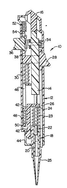
The pipette 10 includes a generally ~longated,
holl~w pipette h~using 12 within which extends a
generally alongated actuating linkage 14. An actuating
button 16, projecting generally from the top of housing
12, is operatively connected to the linkage 14 and
permits manual, generally axial m~vement of the linkage
relative to the pipette housing.
The actuating linkage 14 is operatively
connected with an aspirator 18 mounted generally at the
lower extent of the pipette. housing 12. In the
illustrated embodiment, aspirator l~ includes an
aspirator cylinder 20 fixedly mounted on the housing 12,
1~ and an aspirator piston 22 which is operatively
connected to the actuating linkage 14 for movement
relative to the cylinder 2~ for aspiration of liquids
into the cylinder.
The cylinder and piston arrangement &an be
appropriately sized for aspiration of liquid samples of
the desired volume. While the piston and cylinder
arrangement typically comprise metallic components,
other aspects of the present pipette may be suitably and
economically fabricated from plastic materials or the
like. While the illustrated em~odimen~ of the pipette
10 shows the aspirator 18 as c~mprising the above-
described piston and cylinder construction, the
aspirator may be otherwise configured, such as
comprising a bellows-type aspirator mechanism, as is
known in the art.
In the preferred embodiment, the pipette lO
further includes a biasing spring 23l which in the
illustrated embodiment, comprises a compression coil
spring held in captive relat.ion ~n the piston 22 between
a spring retainer 24 and the cylinder 20. By depressing
- 9 -
the actuating button 16, ~he actuator linkage 14 acts in
opposition to the biasing spring 23 to move the
aspirator piston 22 ~rom a first, generally rai~ed or
retracted positi~n, to a second position. Convenient
operation is thus facilitated, since the bia~ing spring
23 biases the aspirator piston 22 from its second
position into the first position thereof (for creating a
vacuum within the chamber defined by the cylinder 20),
with movement of the actuating linkage, in opposition to
the biasing spring, acting to dispense liquid from the
pipette.
In the preferred form, the pipette 10 includes
a replaceable hollow tip 25 releasably joined to the
aspirator cylinder 20 of the aspirator 18. Liquid flows
into and out of the aspirator tip attendant to operat:ion
of the aspirator 18, thus permitting convenient and
accurate aspiration and dispensing of liquid samples.
In order to ~acilitate replacement o~ the tip 25, the
pipette 10 includes a manually operable tip ejector
mechanism mounted generally within the housing 12,
including a tip ejector rod 26 which is movable into
engagement with the replaceable tip 25 to disconnect the
tip from the aspirator cylinder 20. The ejector rod 26
is operated by an ejector button 28, with the rod 26 and
the button 28 preferably biased away from the tip, to
the position shown in FIGURE 1, by an associated ejector
biasing spring 30 operatively connected with the button
28. In accordance with the illustrated embodiment, the
ejector biasing spring 30 can be mounted in captive
relation between a portion of the ejector button 28
extending adiacent to or through the actuating linkage
14, and a portion of the housing 12 against which the
spring 30 is seated.
In accordance with the present invention, it
can be desirable to aspirate air into the tip 25 of the
-- 10 --
pipette, subsequent to the aspirati~n of a liquid
sample, thus avoiding drop formation and mini~izing the
exposed surface area of the sample. Accordingly, the
pipette 10 includes a manually operable pull-back
5 mechanism which acts to releasably retain the actuator
linkage 14 during the upstroke or retractlon of the
aspirator piston 22. The pull-back mechanism includes a
pull-~ack latch member 34 which is movable generally
laterally of the pipette housinq 12 and generally
laterally of the actuating linkage 14. The latch member
is movable between a release position, shown in FIGURE
1, and a latched position, shown in FIGURE 3, wherein
the latch member engages a stepped portion of the
actuating linkage to retain the actuating linkage
against the action of biasing spring 23.
A pull-back button 36 is operatively connected
with the latch member 3~ for urging the latch member
from its latched position toward its release position in
opposition to an ejector biasing spring 30.
By this arrangement, the aspirator 18, and in
particular, the aspirator piston 22, can be releasably
retained in a third position which is intermediate the
first retracted position and the second position
thereof. In order to release the actuating member 14,
and thus the aspirator piston 2~, from this latched,
third position, the pull-back button 36 is depressed,
thereby disengaging the latch member 34 from the stepped
region of the actuating linkage 14. The biasing spring
23 thereafter urges the aspirator piston 22 ~rom the
third latched position to the fully retracted, first
position.
This arrangement permits the operator of the
pipette to first depress the actuating button 16,
thereby moving the piston 22 from its first position to
its second position, and after placement of the tip 25
in the liquid to be sampled, release the button 16
whereupon th~ aspirator piston 2~ moves upwardly from
its second position. During the downward movement of
the actuating member, the pull-back latch me~ber 34
automatically engages the stepped region of the
actuating linkage, so that upon the return stroke, the
aspirator piston is automatically retained in its third,
intermediate position.
The ~perator then withdraws the tip of the
pipette from the liquid being sampled, and depresses the
pull-back button 3~. This acts to disengage the latch
member 34 from the actuating member 14, thereby
permitting the continued upward movament of the actuator
piston 22, under the influence of biasing spring Z3, so
lS that the piston moves from the third latched position,
to its fully retracted, first position. A quantity of
air is thus aspirated into the tip 25 beneath the liquid
sample.
As will be further described, the present
2~ pipette is desirably configured ~or automatic dispensing
of a liquid sample therein. It is desirable to lock-out
or disable the pull-back mechanism, so that during
automatic operation, the aspirator piston 22 can move
fully from its second position back to its fully
2S retracted, first position.
To facilitate the desired automatic
dispensing, a secondary actuating member 42 is provided,
which is operatively connected with the pi~ton 22 of
aspirator 18 at the spring retainer 24, with the
actuating linkage 14 and piston 22 being movable
relative to the member 42 attendant to operation of the
linkage. In the illustrated embodiment, the pipette
~ousing 12 defines an access opening 44 for the
secondary actuating member 42 for operation of the
actuating member 42 by the associated automatic
dispensing apparatus.
The disablement of the pull-back mechanism is
achieved by the pro~ision of a lock-out rod 4G whioh is
S operatively connected with the secondary ;ictuating
member 42 and the pull-back button 36. Specifically, a
compression spring 48 is held captive between the
actuating member 4~ and a suitable pin ~0 on the lock-
out rod 46. The upper end of the lock-out rod is
operatively connected with a tension ~pring 52, with an
engagement pin 54 being positioned for engagement with
the pull-back button 36, which engagement prevents the
pull-back latch member 34 from moving into the stepped
region of actuating linkage 14 under the influence of
pull-back biasing spring 38.
The illustrated em~odiment is configured such
that the spring 4 a exerts a higher spring force than the
tension spring 52, thus permitting the lock-out rod 46
to move downwardly with the secondary actuatin~ member
42 in opposition to the tension spring 52. Upon
engagement and seating of the engagement pin 54 with the
pull-back button 36, the spring 48 cooperates with the
actuating member 42 and the lock-out rod 46 to provide a
lost-motion mechanism, thereby permitting continued
downward movement of the actuating member 42 relative to
the lock-out rod 46.
With particular reference now to FIGURE5 2 and
4, therein is diagrammatically illustrated the automated
dispensing apparatus 60 of the present system. The
dispensing apparatus 60 is configured to remova~ly
receive the pipette 10 for automated operation thereof,
in particular, for automated metered dispensing of
liquid from within aspirator 18 of the pipette.
Dispensing apparatus 60 inoludes a suitable
3~ housing 62 defining a pipette cavity 64 for receiving
.
2 ~
~ 13 -
the lower end of pipette 10. A pawl-like mPtering
member 66 is positioned in operative association with
the pipette cavity 64 for c~operative engagem~nt with
sacondary actuating member 42.
The dispensing apparatus 60 include~ a driver
68, which may comprise a mechanical, electro-mechanical,
pneumatic, or hydraulic device, which is operatively
connected with the metering member 66 by a suitable
drive linkage 70. The arrangement can include a return
spring 72 operatively connected with the meterin~ member
60. In the illustrated embodiment, the met~ring member
includes a pivotal connection 74 joining the metering
member to the drive linkage 70, with a biasing spring 76
urging the metering member 66 generally toward the
cavity 64, thereby urging the metering member into
engagement with the secondary actuating member 42
through the access opening 44 in the pipette housing.
In the preferred embodiment, the housing 6~ includes a
cam surface 78 which cooperates with the metering member
66 for urging the metering member away from the cavity,
thus facilitating insertion and removal of the
associated pipette.
From the foregoing, the operation of the
present system will be readily appreciated. The
cooperating configuration of pipette 10 and the housing
62 of the dispensing apparatus, including the cavity 64,
act to locate the pipette in a predetermined disposition
generally within the housing 62. During insertion, the
metering member 66 is generally in the position
illustrated in FIGURE 2, ~hus facilitating unencumbered
insertion of the pipette.
To initiate automatic dispensing of the liquid
sample from within the tip 25 of the pipette 1~, the
driver 68 is operated so that the metering member 66 is
moved generally downwardly relative to housing 62. By
.
~` ' .
2 ~ L~
this action, and under the influence of ~iasing sp~ing
76, the metering ~ember is urged into cooperat{ve
angagement with the secondary actuating member 42 of the
pipette. ~pon engagement of the metering member with
the actuating member ~2, continued operation of the
driver effects dispensing of the liquid sample within
the aspirator 18 of the pipette. Suitable automatic
controls are preferably provided to facilitate
dispensing at the æesired rate, and dispensing of the
desired liquid volumes.
As discussed above, downward movement of the
secondary actuating member 42 acts to operate lock-out
rod 46, thereby disabling the pull-b~ck mechanism of the
pipette during the return stroke of the dispensing
system. This permits the dispensing apparatus to return
the pipette piston 22 to its upwardmost, retracted first
position for subsequent reuse by the operator withQut
releasing the pull-back mechanism of the pipette.
During the upward stroke, the metering member 66
cooperat~s with the cam surface 78 of the housing 62 so
that member 66 returns to its generally retracted
position relative to the cavity 62.
The present system can be provided in various
configurations, depending upon the desired sampling and
dispensing operations to be performed. While the
present inventio~ has been disclosed as including a
single pipette cassette lO, the arrangement may be
readily configured to include ~ultiple pipettes operated
in cooperation with each other. Releasable connection
means can be provided in order to suitably connect
plural ones of the pipettes together. The pipettes may
be suitably configured for independent operation, or may
be arranged to operate in ganged fashion for common
aspiration and dispensing.
2 ~ t-;l
- 15 -
From the foregoing, it will be observed that
numerous modifications and variations can be effected
without departing from the true spirit and ~cope of the
novel concept of the present invention. It i5 to be
understood that no limitation with respect to the
present disclosure is intended or should :be inferred.
The disclosure is intended to cover by the appended
claims all such modifications as fall within the scope
of the claims.
.