Note: Descriptions are shown in the official language in which they were submitted.
2~123~
TNTEGRATED CRACKING ,_ETHERIFICAT_N AND
OLEFIN UPGRADING PROCESS
The present inVentiQn relates to a process ~or
producing high octane gasoline from liyht olefinic
streams produced in a hydrocarbon cracking process.
More specifically, the invention relates to an
integrated three-stage process which includes a first
cracking stage, a second intermediate product
deacidification and fractionation stage, and a third
intermediate product upgrading stage.
Environmental regulations restricting the use of
octane enhancing lead additives for internal combustion
engines as well as the shift in the automotive industry
toward more efficient higher compression ratio engines
have prompted the petroleum refining industry to seek
alternate processes for meeting the demand for high
octane unleaded gasoline.
In order to meet these requirements, the industry
has developed non-lead octane boosters and has
reformulated high octane gasoline ~o incorporate an
increased fraction of aromatics. While these and other
approaches will fully meet the technical requirements
of regulations requiring elimination of gasoline lead
additives and allow the industry to meet the burgeoning
market demand for high octane gasoline, the impact on
the cost of gasoline is significant.
Catalytic cracking processes manufacture a major
segment of the total gasoline pool produced in modern
oil refineries by upgrading gas oil and heavier
feedstreams to a lighter product list including
gasoline and distillate as well as C4- aliphatics rich
in olefins. Examples of such catalytic cracking
processes are described in P. B. Venuto and E. T.
Habib, Jr., Fluid Catalytic Cracking with Zeolite
Catalysts (1979) as well as U.S. Patents 2,383,686 to
2~1238
F s34s - 2 -
Wurth; 2,689,210 to Leffer; 4,093,~37 to Gross et al.;
4,118,338 to Gross et al.; and 4,411,773 to Gross.
To increase the overall yield ~f high octane
gasoline from catalytic cracking units, processes have
been developed which upgrade the C4- by-products of the
cracking process. With the advent of these light
aliphatics upgrading processes, the demands on the
catalytic cracking unit product fractionation section
have also changed. Specifically, the C4 aliphatics
upgrading processes operate at relatively high
temperature conditions, typically above about 371C
(700~F). For this reason, the H2l ~2S, and mercaptan
sulfur contents of the C4- aliphatic streams from the
catalytic cracking unit product fractionation section
r 15 are critical, not only to meet product specifications
and to prevent accelerated catalyst deactivation, but
also to assure safe and reliable unit operation using
the most economical materials of construction. It has
been found that levels of H2S, H2, and mercaptan sulfur
levels which were completely acceptable for lower
temperature light aliphatics upgrading processes such
as HF or H2S04 catalyzed alkylation can markedly
accelerate corrosion, pitting and cracking in carbon
steel and lower alloy vessels under the more severe
temperature conditions associated with the catalytic
upgrading processes presently under consideration.
Thus it would be desirable to provide the light
aliphatics upgrading process associated with the
catalytic cracking unit with a C2-C4 aliphatic stream
which is relatively free from H2S, H2, and mercaptan
sulfur.
Catalytic cracking process units typically include
a main fractionator, commonly called the column, which
receives cooled reactor effluent from the catalytic
cracking process. The main column fractionates this
reactor effluent into a plurality of streams including
2~ 3~
F~5349 - 3 -
clarified slurry oil, heavy cycle oil, light cycle oil,
unstabilized gasoline and an overhead gas stream rich
in C4- olefins. The gasoline and lighter components
are then further fractionated in an unsaturated gas
plant which typically includes, in order, a deethanizer
absorber, a debutanizer and a depropanizer.
The deethanizer absorber splits the gasoline and
lighter material into a C2- overhead gas stream and a
C3+ bottoms stream. The C2- overhead gas stream may
optionally be treated in a sponge absorber to further
sorb C3+ components before acidic components such as
hydrogen sulfide, carbon dioxide and hydrogen cyanide
are removed in a purification sorption column. Having
heen treated to reduce its acidic gas content, the
deethanizer absorbar overhead stream is then charged to
a fuel gas header to be burned for fuel in the refinery
complex.
The deethanizer absorber bottom stream is then
charged to a debutanizer fractionator where it is split
into a C5+ gasoline stream rich in olefinic components
and a C3-C4 overhead stream. The debutanizer
fractionator is typically designed to meet a bottom
stream gasoline volatility specification requiring
vapor pressure of less than about 69 kPa (10 psi).
Finally, the debutanizer overhead stream, rich in C3-C4
olefins, may be fractionated into a propane/propylene
overhead stream and a butane/butylene bottoms stream.
This step is most often employed when additional light
aliphatics upgrading capacity is available, for
example, an alkylation process unit for converting iso-
and normal C4 aliphatics to high octane alkylate
gasoline. The C3-rich depropanizer or debutanizer
overhead stream may be sold as liquefied petroleum gas
(LPG), but first must be treated in a mercaptan sulfur
removal process to meet sulfur content specifications.
2 ~ 3 8
F-5349 _ 4 _
One example of such a process is the MProx process
(trademark and/or service mark o~ UOP, Inc.).
The incremental volume of c2- fuel gas generated
by a catalytic cracking process may increase the total
refinery fuel gas volume beyond that needed to ~ulfill
its fuel gas consumption and sales requirements. To
assure compliance with environmental regulations
governing content and volume of gases exhausted to the
atmosphere, fuel gas production is limited ko the total
volume which can be consumed within the refinery, sold
ko consumers beyond the battery limits of the refinery,
or flared in accordance with the applicable
environmental permits. Thus if the incr mental volume
of fuel gas generated by the catalytic cracking unit
exceeds th~ capacity of facilities for its disposition,
the cracking unit feedrate or reaction severity must be
reduced. Neither option i~; economically desirable.
The ideal solution would ~e to decrease fuel gas volume
by shifting the overall yield from the catalytic
cracking uni~ away from C2- components and toward more
valuable high octane C5+ gasoline. The acid gas
components of the catalytic cracking unit reactor
effluent stream tend, however, to ba carried with
ethane and ethylene. Clearly, then, the problem of
excess fuel gas production cannot be solved merely by
shifting the cut points in a conventional catalytic
cracking product fractionation section because the
downstream light aliphatics upgrading process would be
exposed to hydrogen and acid gases under severe
temperature conditions.
A number of acid gas removal processes are
commercially available for treating this overhead
stream including chemical solvent as well as physical
sorption processes~ Chemical solvent techniques
include countercurrent contacting with monoethanolamine
(MEA), diethanolamine (DEA) and hot potassium
20~38
F-5349 - 5 -
carbonate. Physical sorption techniques employ solid
sorbents such as mol~cular sieves, activated charcoal
and iron sponge.
Conventionally, these acid gas removal processes
are installed downstream of the sponge absorber and
debutanizer. Consequently, the acid gases are carried
through the various upstream separation processes of
the unsaturated gas plant (USGP) including the
absorber-deethanizer, sponge absorber and debutanizer.
This configuration tends to increase the rate of acid
gas induced corrosion of a large portion of the vessels
and ancillary equipmant in the USGP, leading to
increased maintenance operations and plant downtime.
Under the more severe temperature conditions of
catalytic aliphatics upgrading processes, streams
containing these acidic components readily attack
carbon steel and the lower chromium- and
molybdenum-containing steel alloys, and may cause
cracking, pitting, blistering, or general thinning.
The available light aliphatics upgrading
processes, include catalytic aromatization,
oligomerization and etherification. Catalytic
aromatization converts tha light aliphatics over a
catalyst, for example a medium-pore zeolite catalyst
such as ZSM-5, to a product mixture rich in aromatics.
Oligomerization and olefin interconversion may employ
similar catalysts, but are typically conducted under
less severe temperature conditions. Etherification
reacts olefins with alcohols to ~orm ethers use~ul as
octane-enhancing gasoline additives. For example,
isobutylene may be reacted with methanol over an acidic
catalyst to produce methyl-tertiary butyl ether (MTBE)
and that isoamylenes may be reacted with methanol over
an acidic catalyst to produce tertiary-amyl methyl
ether (TAME).
2~4~238
F-5349 - 6 -
In U.S. Patents 4,~30,635; 4,826,507; and
4,788,365 to Harandi and Owen the ability of zeolite
type catalyst to con~er~ methanol to ol~fins is
utilized by directing unreacted methanol from an
~therification reaction to a zeolite catalyzed
conversion reaction for conversion to ole~in, thereby
obviating the need to separate and recycle methanol in
the etherification reaction.
The process for the conversion of methanol to
olefins is but one in a seri~s of analogous processes
based upon the catalytic capabilities of zeolites.
Depending on various conditions of space velocity,
temperature and pressure methanol, and lower oxygenates
in general, can be converted in the presence of zeolite
. 15 type catalyst to olefins which may then oligomerize to
provide gasoline or distillate or be converted further
to produce aromatics. In another application of
zeolite catalysis, light ole~ins can be interconverted
or redistributed at low pressure and high temperature
to produce higher olefins rich in isoalkenes.
Recent developments in zeolite catalyst and
hydrocarbon conversion processes have created interest
in using olefinic feedstocks for producing C5+
gasoline, diesel fuel, and higher boiling hydrocarbon
products. In addition to the basic work derived from
medium pore zeolites such as ZSM-5, a number of
discoveries have contributed to the development of a
new industrial process, known as ~obil Olefins to
Gasoline/Distillate ("MOGD"). This process has
significance as a safe, environmentally acceptable
technique fsr utilizing feedstocks that contain lower
olefins, especially C3-C5 alkenes~ In U.S. Patents
3,960,978 and 4,0~1,502, Plank, Rosinski and Givens
disclose conversion of C2-C5 olefins, alone or in
admixture with paraffinic components into higher
hydrocarbons over crystalline zeolites having
F-534s - 7 -
controlled acidity. Garwood et al. have also
contributed improved processing techniques to the MOGD
system as in U.S. Patents 4,150,062; 4,211,640; and
4,227,992. The conversion of olefins to gasoline using
a fluidized catalyst bed is the subject of U.S. Patent
application serial number 006407 to Owen et al. The
above identified disclosures are incorporated herein by
reference. The MOGD proc~ss may produce low octane
gasoline. This disadvantage requires further
downstream processing of the product so produced in
order to provide a gasoline product with useful road
octane value. Improvement of the process to provide an
instant higher octane value gasoline product has been a
much sought after objective in that field of art.
~- l5 These two processes, etherification and olefin
oligomerization/interconversion have been
advantageously integrated to provide a high octane
ether-rich gasoline product from aliphatic hydrocarbon
and lower al~yl alcohol feedstreams. The Mobil Olefins
to Ethers and Gasoline (MOEG) process produces methyl
tert-butyl ether (MTBE) and/or tertiary amyl methyl
ether (TAME) by a two-step reaction sequence utilizing
a catalytic etherification step as described above,
followed by a zeolite catalysis to convert unreacted
alcohol and olefins in the etherification effluent.
MTBE and TAME are formed conventionally by contacting a
stream rich in isobutylene and isoamylene in the
presence of a acid catalyst, e.g. a sulfonic acid resin
catalyst such as Amberlyst 15, which catalyzes the
iso-olefin/alcohol reaction. This process is detailed
in U.S. Patents 4,830,635; 4,826,507; and 4,788,365 to
Harandi and Owen, which are incorporated herein by
reference for details of the MOEG process.
Thus it is clear that a process for shifting
product yield in a catalytic cracking unit away from
C4- light aliphatics, particularly C2- fuel gas, to
~0 ~1238
F-5349 - 8 -
favor production of high octane gasoline would provide
substantial operational and economic benefits.
Further, it would be desirable to provide the light
olefin upgrading section of such a process with a
feedstock of suffiGient purity to meet the application
environmental standards and product quality
specifications while also avoiding the incremental
capital costs associated with alloyed process
equipment.
The present inventive process comprises a first
cracking stage, a second intermediate product
deacidification/ fractionation stage, and a third
intermediate product upgrading stage to reduce the
total C4- gas production from the cracking process
-. 15 while increasing C5+ gasoline volume and octane number.
By shifting yield away from C4- gas toward C5+ liquid,
fuel gas as well as LPG production are beneficially
decreased, thus minimizing the effects of refinery fuel
gas volume limitations on the cracking process while
also decreasing LPG mercaptan sulfur removal treatment
costs. Further, the present process limits the
concentrations of H2S, H2, N2, and mercaptan sulfur
flowing to the light aliphatics upgrading reaction zone
to minimize the use of nickel- and chromium-alloyed
process equipment. Still further, the present
integrated process limits the flow of these undesirable
acid gas constituents to the light aliphatics upgrading
reaction zone without sacrificing process flexibility.
The terms "cracking stage" and "cracking process"
as used herein encompass thermal cracking processes,
e.g. delayed coking, catalytic cracking processes, e.g.
Thermofor Catalytic Cracking (TCC) and Fluid Catalytic
Cracking (FCC), as well as steam cracking commonly used
in industry for ethylene production. In the most
preferred embodiment of the invention, the cracking
2 ~ ,7 ~ ~
F--5349 _ 9 _
stage comprises a Fluid Catalytic Cracking (FCC)
process.
In a first method aspect, the invention provides
an integrated process for upgradiny gasoline and
lighter products ~rom a cracking process comprising the
steps of:
compressing and cooling a C4~ cracking process
product stream to provide an ethene-rich vapor stream
and a first condensed C3+ aliphatic stream;
countercurrently contacting the ethene-rich vapor
stream and the condensed C3~ aliphatic stream with a
C5+ li~uid sorbent stream comprising cracked gasoline
under superatmospheric pressure in an absorber column
to sorb a major portion of C2+ components;
_. 15 recovering a methane rich overhead stream from the
absorber column;
recovering an absorbar bottom stream from the
absorber column containing C2+ components;
fractionating the absorber bottom stream in a
first fractiona~or to evolve an overhead stream rich in
C2-C5 aliphatics and a C5+ cracked gasoline stream;
contacting at least a portion of the first
fractionator overhead stream with an acid
etherification catalyst in a guard bed zone to sorb at
~5 least a portion of the catalyst poisons in the
debutanizer overhead stream including
nitrogen-containing compounds:
mixing effluent from the guard bed with an amount
of a primary alcohol sufficient to etherify the C4-C5
components of the guard bed effluent stream;
contacting the mixture of primary alcohol and
~uard bed effluent with an acid etherification catalyst
under etherification conversion conditions to form a
product mixture containing high-octane gasoline rich in
ethers as well as unconverted oxygenate and C4-
aliphatic hydrocarbons;
3 8
F-5349 - 10 -
fractionating the high octane gasoline product
mixture in a second fractionator into an overhead
stream containing unconverted oxygenate and C4-
aliphatics and a bottom stream containing ether-rich
S high octane gasoline; and
contacting the second fractionator ov~rhead stream
with a zeolite having a Constraint Index between 1 and
12 under conversion conditions to upgrade the
unconverted oxygenate and aliphatics contained in the
second fractionator overhead stream to C5+ gasoline.
In a second method aspect, the invention provides
a process for upgrading light olefinic crackate gas
from hydrocarbon cracking comprising the sequential
steps of:
. 15 compressing and cooling a C4- cracking process
product stream to provide an ethene-rich vapor stream
and a first condensed C3+ aliphatic skream;
deacidifying the ethene-rich vapor stream and the
first condensed C3+ aliphatic stream by
countercurrently contacting the ethene-rich vapor
stream and the first condensed C3+ aliphatic stream
with acid absorbant;
countercurrently contacting the deacidified
ethene-rich vapor stream and the deacidified condensed
C3+ aliphatic stream with a C5+ liquid sorbent stream
comprising a cracked gasoline under superatmospheric
pressure in an absorber column to sorb a major portion
of C2+ componants;
recovering a methane-rich overhead stream from the
absorber column:
recovering an absorber bottom stream from the
absorber column containing C2+ components;
fractionating the absorber bottom stream to evolve
an overhead stream rich in C2-C5 aliphatics and a C5+
cracked gasoline bottom stream; and
2 ~ 2 ~ ~
F-5349 - 11 -
contacting the C2-C5 overhead stream with a
zeolite having a Constraint Index between about 1 and
about 12 under conversion conditions to upgrade
aliphatics contained in the C2-C5 overhead stream to a
product stream enriched in C5+ liquid hydrocarbons.
In its apparatus aspects, the invention includes
an apparatus for upgrading light olefinic crackate gas
from hydrocarbon cracking comprising:
a compressor for increasing the pressure of a C4-
cracking process product stream;
a cooler for at least partially condensing the
compressed C~- stream of (a), above;
an accumulator drum for receiving an at least
partially condensed C~- stream, the accumulator drum
. 15 having a first outlet conduit positioned in an upper
section of the accumulator drum for withdrawing
ethene-rich vapor and a second outlet conduit
positioned in a lower section of the accumulator drum
for withdrawing liquid containing C3+ componPnts;
an absorber tower for countercurrently contacting
the ethene-rich vapor and the liquid containing C3+
components with a C5+ liquid sorbent, the absorber
tower being in communication with the accumulator drum
via the first and the second outlet conduits, the
absorber tower having sufficient condenser, reboiler
and fractionation capacity to provide an ov~rhead
stream rich in methane, the absorber tower optionally
containing a stripping zone;
a first fractionator for fractionating a bottom
stream withdrawn from the absorber tower into a C5+
cracked gasoline bottom stream and'an overhead stream
rich in C2-C5 aliphatics;
a valved alcohol injection conduit for admixing a
controlled quantity of alcohol with the first
fractionator overhPad stream;
~412~g
F-5349 - l2 -
an etherification reactor for ~ontacting the
admixture of the alcohol and the first debutanizer
fractionator overhead stream with an acid
etherification ca~alyst under ehtherification
conversion conditions to form a product mixture
containing high octane gasoline rich in ethers;
a second fractionator for separating the etherification
reactor product mixture into an overhead stream
containing unconver~ed alcohol and C4- aliphatics and a
bottom stream of ether-rich high octane gasoline; and
an alcohol/aliphatics upgrading reactor for
contacting said second debtanizer overhead stream with
a composite catalyst containing a zeolite having a
Constraint Index of between about l and l2 under
r 15 conversion conditions whereby a product stream
containing C5+ gasoline is formed.
Figure l is a simplified schematic diagram showing
the major processing steps of a first embodiment of the
intermediate product fractionation section of the
process of the present invention.
Figure 2 is a schematic diagram showing the major
processing steps of a second embodiment of the
intermediate product fractionation section of the
invention which may optionally be us~d to effect higher
C4- aliphatics recovery.
Figure ~ is a simplified schematic diagram showing
major processing steps of the intermediate product
fractionation and light aliphatics upgrading stages of
the present invantion.
In a preferred embodiment, the present process
comprises three processing stages: a first catalytic
cracking stage, a second intermediate product
fractionation stage, and a third light aliphatics
upgrading reaction stage. The first catalytic cracking
stage comprises any suitable catalytic cracking
configuration, as described more fully hereinbelow.
2~238
F-5349 - 13 -
The se~ond stage fractionates and purifies the Cg-
intermediate product streams from the catalytic
cracking process to prolong catalyst life in the
downstream aliphatics upgrading stage, to achieve the
desired purity both in the fuel gas and in the finished
products.
The aliphatics upgrading stage may comprise
aromatization, oligomerization, etherification or a
combination of oligomerization and etherification. In
the preferred embodiment of this invention, the
aliphatics are upgraded first via etherification, which
comprises reacting an alcohol, preferably a primary
alcohol such as methanol with a hydrocarbon feedstock
containing olefins and particularly isoolefins such as
isobutene to produce methyl tertiary butyl ethers and
other ethers, and then unconverted olefins and alcohol
are upgraded via oligomerization.
The Catalytic Crackina Staqe
In the first stage of the present process, a heavy
hydrocarbon feedstock, for example, a yas oil, is
cracked to a lighter product slate including
distillates, gasoline, and C4- aliphatics. The fluid
catalytic cracking (FCC) process is most preferred for
this first stage and has become well-established in the
petroleum refining industry for converting higher
boiling petroleum fractions into lower boiling
products, especially gasoline.
In the fluid catalytic process, a finely divided
solid cracking catalyst is used to promote the cracking
reactions which take place in the feed. The catalyst
is used in a very finely divided form, typically with a
particle size range of 20-300~ (20-300 microns), with
an average of about 60-75~ (60-75 microns), in which
form it can be handled like a fluid (hence the
designation FCC). In this form, the catalyst is
circulated in a closed cycle between a cracking zone
2V~123X
F-5349 - 14 -
and a separate regeneration zone. In the cracking
zone, hot catalyst is brought into contact with the
feed so as to effect the desired cracking reactions
after which the catalyst is separated from the cracking
products which are removed from the cracking reactor to
the associated fractionation equipment for separation
and further processing. During the cracking reaction,
coke is deposited on the catalyst. This deposit of
coke masks the active sites and temporarily deactivates
the catalyst. Such temporarily deactivated catalyst is
commonly called spent catalyst. The catalyst must then
be regenerated before it can be reused. Fortunately,
the coke deposit can be made to serve a useful purpose.
Cracking is an endothermic reaction. Although, in
. 15 principle, heat could be supplied by raising the
temperature of the hydrocarbon feed prior to contact
with the catalyst, this would thermally crack the feed
so that very littlP control could be effected over the
product distribution. Additionally, the coke formed
would deposit on furnace tubes and other equipment used
for heating and conveying the feed to the cracker,
causing operational problems. For this reason, it is
generally preferred to supply the heat to the cracking
reaction by means of the catalyst~ The feed may,
however, be preheated to a certain degree in order to
maintain an appropriate heat balance in the cycle.
Heat for the catalytic cracking process is
supplied by the regeneration step in which the spent
catalyst is subjected to oxidative regeneration to
remove the coke. This coke-burning step is strongly
exothermic and raises the regenerated catalyst
temperature such the the sensible heat imparted to the
catalyst during regeneration is sufficient to supply
the endothermic heat of reaction for the cracking step.
The regeneration takes plase in a separate
regenerator vessel. Catalyst is maintained in a
~0~12~',8
F-5349 - 15 -
fluidized bed in a lower section of the regenerator
vessel and an oxygen-containing gas, usually air, flows
through a distribution grid which is desiqned to
provide efficient mixing of air with th~ spent, coked
catalyst. During the regeneration step, the coke on
the spent catalyst is oxidized and the heat from the
oxidation is transferred to the catalyst to raise its
temperature to the requisita level for continuing the
cracking reactions. The hot, freshly-regenerated
catalyst is then re~urned to the cracking zone for
contact with further feed together with any recycle.
Thus, the catalyst circulates continuously in a closed
cycle between the cracking zone and the regenerating
zone with heat for the endothermic cracking reactions
r 15 being supplied in the regenerator by oxidative removal
of the coke deposits which are laid down during the
cracking portion of the cycle. In order to maintain
the desired level of catalyst activity and selectivity,
a portion of the circulating inventory of catalyst may
be withdrawn intermittently or continuously with fresh,
make-up catalyst bein~ added to compensate for the
withdrawn catalyst and the catalyst losses which occur
through attrition and loss of catalyst from the system.
A further description of the catalytic cracking
process and the role of regeneration may be found in
the monograph, "Fluid Catalytic Cracking With Zeolite
Catalysts", Venuto and Habib, Marcel Dekker, New York,
1978. For additional details of FCC operation, see
U.S. Patents 2,383,636 to Wirth; 2,689,210 to Leffer;
30 3,338,821 to Moyer et al.; 3,812,029 to Snyder, Jr.;
4,093,537 to Gross e~ al.; and 4,218,306 to Gross et
al.
A particularly preferred FCC configuration is
disclosed in U.S. Patent 4,840,928 to Harandi and Owen
which teaches a ~luid catalytic cracking (FCC) process
in which catalyst withdrawn from the regenerator is
2 0 ~ 3 8
F-5349 - 16 -
cooled ~y direc~ contact with an alkane-rich stream in
an external catalyst cooler. Details of FCC operation,
and particularly the details of separating the
fluidized catalyst from the reaction products axe also
taught in u.s. Patents 4~0~3,899 to Anderson; 4,404,095
to Haddad; 4,502,947 to Haddad; 4,579,716 to Kra-mbeck;
4,581,205 to Schatz; 4,588,558 to Kam; 4,~06,814 to
Hadd~d; 4,623,446 to Haddad; 4,624,772 to Krambeck;
4,654,060 to Haddad; U.S. Patent 4,737,346 to Haddad;
and 4,749,471 to Kam~
Intermediate~Product Fractionation
The sequence of deacidification and separation
steps in the second stage o~ the present process,
intermediate product fractionation, is critical to
-- 15 achieving the beneficial results of the invention.
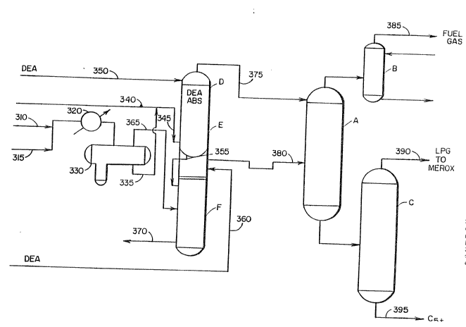
Referring to Figure 1, the major processing steps of
the intermediate product fractionation stage of the
present process are described. In this configuration,
the principal separation operations of the U5GP
represented by deethanizer-absorber zone A, sponge
absorber zone B and debutanizer zone C are located
downstream of amine absorber operations. This is
achieved by installing alkanolamine absorber D
containing two amine absorption zones E and F upstream
2~ of the aforëstated separation zones. Examples of
suitable alkanolamines include monoethanolamine,
diethanolamine, triethanolamine, and methyl
diethanolame, merely to name a few. Amine absorption
zones E and F are interconnected such that amine can
flow from zone E to zone F. In a preferred
configuration, compressor outlet gases from line 310
and interstage liquids from line 315 are cooled in
exchanger 320 and separated in vapor/liquid accumulator
330. The liquid fraction is withdrawn from a lower
section of vapor/liquid accumulator 330 via line 335
and is mixed with an unstabilized gasoline feedstream
, 3 ~
F-5349 - 17 -
from line 3~0. The mixture O:e liquid from accumulator
330 and the unstabilized gasoline is introduced into a
bottom portion of amine absorber zone E in
countercurrent flow with a lean diethanolamine (DEA~
mixture introduced into a top portion of zone E.
Partially spent DE~ is passed via line 355 to an upper
portion of zone F in combination with fresh DEA which
is added through line 360. The gaseous fraction is
passed through line 365 to a lower portion of ~one F in
countercurrent contact with DEA. Rich DEA withdrawn
from a lower portion of zone F. The deacidified
unstabilized gasoline stream is passed overhead through
line 375 from zone E to an upper portion of absorber
deethanizer A. The deacidified vapor fraction is
transferred via line 380 from zone F to a middle
portion of deethanizer A. From the
deethanizer-absorber a deacidified overhead is treated
in sponge absorber B to produce deacidified fuel gas
which is charged to the refinery fuel gas system (not
shown) through line 385. The bottom fraction from zone
A is separated in debutanizer C to produce deacidified
LPG which is taken overhead through line 390 and
deacidified C5 hydrocarbons which are withdrawn as the
bottom fraction through line 395.
In the intermediate product fraction stage as
described in Figure 1, FCC unstabilized gasoline and
the high pressure separator liquids are mixed and amine
treated upstream of the deethanizer-absorber.
Preferably, about 50-80% of the total amine circulation
rate is sent to this amine absorber. The
deethanizer-absorber vapor feed is then sent to another
amine absorber where preferably 20-50% of the total
amine circulation rate is fed to the absorber upper
tray and the rich amine from the other amine absorber
is fed to a few trays below the upper tray.
- 2~123~
F-5349 - 18 -
Referring now to Figure 2, a higher recovery
variation of the intermediate product fractionation
stage o~ the ins ant invention is presented~ As in the
embodiment of tha intermediate product fractionation
S stage of this invention descri~ed above with reference
to Figure 1, the USGP separation zones A, B, and C are
located downstream of the DEA amine absorber D. In the
embodiment of the intermediate product fractionation
stage described in Figure 2, howevar, absorber D
contains three separate but interconnected amine
absorber zones E, F, and G, each of which are fed with
a fresh amine stream. Lean DEA is introduced through
line 410 into a top portion of zone D. Partially spent
DEA flows through line 415 from a bottom portion of
. 15 zone E to the top of zone F. Fresh DEA is added to the
top of zone F via line 420. Partially spent DEA is
withdrawn from the bottom of zone F is charged to the
top of zone G through line 425 together with fresh DE~
which is added to the top of zone G through line 430.
Rich DEA is withdrawn from a bottom portion of zone G.
Unstabilized gasoline 10ws through line 440 into the
bottom portion of zone F countercurrent to the flow of
DEA. The liquid fraction from separator 455 is
introduced to the bottom portion of zone E via line
450, also countercurrent to the flow of DEA while the
vapor portion is passed through line 460 from the
separator is passed to the lower portion of zone F.
Deacidified unstabilized gasoline is withdrawn
from a bottom portion of zone E via line 465 and
introduced to a top portion of the deethanizer-absorber
zone A. The deacidified vapor fraction is transferred
via line 470 to the mid portion or lower portion of
zone A from a bottom portion of zone F while an
overhead stream from zone E is introduced into a lower
portion of deethanizer-absorber zone A.
20~1238
~-5349 19 -
As in the previously described configuration, the
deacidified effluents fro~ zone A are further treated
and separated in spsnge absorber B and debutanizer C to
produce deacidified fuel gas, deacidified LPG, and
deacidified C5 hydrocarbons.
In the intermediate product fractionation stage
described in Figure 2, the three deethanizer-absorber
feedstreams including the high pressure separator
liquid, high pressura separator vapor, and FCC
unstabilized gasoline are amine treated in three amine
absorbers. In this design the USGP LPG recovery is
improved due to higher hydrocarbons partial pressure in
the dee~hanizer-absorber and sponge absorber and
deacidification after removing the recoverable acids
and C02.
The unique deacidification configuration of the
intermediate product fractionation stages described
above with reference to Figures 1 and 2 allows the
deethanizer to be controlled to shift ethane/ethylene
to the bottom stream rather than to take the bulX of
the C2 material overhead as fuel gas. This operational
flexibility is enhanced by upstream deacidification,
and allows the debutanizer to produce an overhead gas
stream containing not only C3~C4 aliphatics but also a
substantial portion of the C2 hydrocarbons produced in
the cracking process. Further, shifting the
deethanizer cut point tends to reduce the relative
hydrogen concentration in the debutanizer overhead
stream so that the light C2-C5 aliphatics may be
catalytically upgraded under relatively severe
temperature conditions without incurring incremental
capital costs for high alloy process equipment.
The Liaht Aliphatics Uparading Sta~e
The final stage of the process of the present
invention upgrades the purified intermediate C2-C4
2~123~
~-5349 - 20 -
product stream via aromatization, oligomerizaticn, or
etharification.
Aromatiza~tion
The following representative U.S. patents
Pxemplify the feed compositions and process conditions
for aliphatics aromatization reactions compatible with
the final stage of the present proces~.
U.5. Patent Number 3,756,942 discloses a process
for the preparation o~ aromatic compounds in high
yields which involves contacting a particular feed
consicting essentially of mixtures of paraffins and/or
olefins, and/or naphthenes with a crystalline
aluminosilicate, e.g. ZSM-5, under conditions of
temperature and space velocity such that a significant
portion of the feed is converted directly into aromatic
_
compounds.
U.S. Patent Number 3,759,821 discloses a process
for upgrading catalytically cracXed gasoline.
U.S. Patent Number 3,760,024 teaches a process for
the preparation of aromatic compounds involving
contacting a feed consisting essentially of C2-C4
paraffins and/or olefins with a crystalline
aluminosilicate, e.g. ZSM-5.
The article "M2 Forming-A Process for
Aromatization of Light Hydrocarbons" by N.Y. Chen and
T.Y. Yan, 25 IND. ENG. CHEM. PROCESS DESo DEV. 151
(1986) discusses the mechanisms of dehydrogenation and
aromatization but is not presented to limit the
invention by theory.
Etherification
The C2 C4 intermediate produ~t stream may also be
upgraded to a high octane gasoline blending component
by etherification. The most desirable aliphatic
feedstock for etherification is rich in isobutylene
which may be reacted with methanol over an acidic
catalyst to produce methyl-tertiary butyl ether (MTBE).
2 3 8
F-534s - 21 -
Isoamylenes may also be reacted with methanol over an
acidic catalyst to produce tertiary-amyl methyl ether
(TAME). Methanol may be readily obtained from coal by
gasification to synthesis gas and conversion of the
synthesis gas to methanol by well-established
industrial processes. As an alternative, the methanol
may be obtained from natural gas by other conventional
processes, such as steam re~orming or partial oxidation
to make the intermediate syngas. Crude methanol from
such processes usually contains a significant amount of
water, usually in the range of 4 to 20 wt%. ~he
etherification catalyst employed is preferably an ion
exchange resin in the hydrogen ~orm; however, any
suitable acidic catalyst may be employed. Varying -- 15 degrees of success are obtained with acidic solid
catalysts; such as, sulfonic acid resins, phosphoric
acid modified kieselsuhr, silica alumina and acid
zeolites.
The etherification process of the intermediate
product upgrading stage most preferably includes not
only the catalytic etherification reaction but also an
acid zeolite catalyzed olefin oligomerization reaction
to maximize yield and to ~implify product separation.
The etherification and the oligomerization reaction
zones are operatively connected in a synergistic
combination whereby etherification reaction effluent is
utilized to provide additional reactive tertiary
olefins by zeolite catalysis to provide olefin
interconversion and oxygenate conversion. This
improved etherification process is commonly known as
the Mobil Olefins to Etherates and Gasoline Process
(MOEG). U.S. Patents 4j788,365; 4,826,527; 4,830,635;
4,835,329; 4,854,~39; and 4,885,421 to Harandi and Owen
as well as U.S. Patent 4,886,925 to Harandi teach
integrated etherification/interconversion processes.
2~238
F-5349 ~ 22 -
Isomerization, polymerization/ oligomerization,
alkylation and cracking reactions may be controlled in
the acid catalysis zone to obtain a desirable
distribution of normally liquid hydrocarbons useful in
making gasoline and distillate range fuels.
Advantageously, at least a portion of the gasoline
range hydrocarbons are recovered with C5+ etherate
octana enhancers useful in quality motor fuels. MTBE
and TAME are preferred etherates.
The reaction of methanol with isobukylene and
isoamylenes at moderate conditions with a resin
catalyst is known technology, as provided by R. W.
Reynolds, et al., The Oil and Gas Journal, June 16,
1975, and s. Pecci and T. Floris, Hydrocarbon
-. 15 Processinq, December, 1977. An article entitled "MTBE
and TAME - A Good octane Boosting Combo," by J.D.
Chase, et al., The Oil and Gas Journal~ April 9, 1979,
pages 149-152, discusses the technology. A preferred
catalyst is a bifunctional ion exchange resin which
etherifies and isomerizes the reactant streams.
typical acid catalyst is Amberlyst 15 sulfonic acid
resin.
MTBE and TAME are known to be high octane ethers.
The article by J.D. Chase, et al., Oil and Gas Journal,
April 9, 1979, discusses the advantages one can achieve
by using these materials to enhance gasoline octane.
The octane blending number of MTBE when 10~ is added to
a base fuel (R+O = 91) is about 120. For a fuel with a
low motor rating (M+O = 83) octane, the blending value
of MTBE at the 10% level is about 103. On the other
hand, for an (R~O) of 95 octane fuel, the blending
value of 10% MTBE is about 114.
Processes for producing and recovering MTBE and
other methyl tertiary alkyl ethers from C4-C7
isoolefins are known to those skilled in the art, such
as disclosed in U.S. Patents 4,544,776 to Osterburg, et
~0~23~
F-5349 - 23 -
al. and 4,603,225 to Colaianne et al. Various suitable
extraction and distillation techniques are known for
recovering ether and hydrocarbon streams from
etherification e f fluent.
InterconversionfOliqom~erization
The final aliphatics upgrading stage may also
Gomprise olefins interconversion or oligomerization.
This process is commonly known as the Mobil Olefins to
Gasoline/Distillate/
Lubricants Process (MOG/MOGD/MOGDL3. Operating details
for typical MOGD units are disolosed in U.S. Patents
4,456,779; 4,497,968 to Owen et al.; and 4,433,185 to
Tabak.
In the process for catalytic conversion of olefins
to heavier hydrocarbons by catalytic oligomerization
using an acid crystalline zeolite, such as ZSM-5,
process conditions can be varied to favor the formation
of either gasoline, distillate or lube range products.
At moderate temperature and relatively high pressure,
the conversion conditions favor distillate range
product having a normal boiling point of at least 165C
(330F). Lower olefinic feedstocks containing C2-C5
alkenes may be converted selectively; however, the low
severity distillate mode conditions cannot completely
2S convert the fraction of ethene in the feed. Propene,
butenes and others ma~ be converted to the extent of
more than 95% per pass in the distillate mode.
In the MOGD process, light olefins are
oligomerized to high molecular weight distillate range
olefins over ZSM-5. In that process olefin molecular
weight growth through a sequence of oligomerization and
cracking reactions is thermodynamically forced at
relatively high pressures of about 5600 kPa (800 psia)
and relatively low temperatures o~ about 260C (500F).
At much lower pressure, thermodynamics restrict the
olefin distribution to low molecular weight. This is
2 3 ~
F-5349 - 24 -
the basis for the olefin interconversion process, i.e.,
to operate under conditions where lower olefins, such
as c2-C~ olefins can be converted to an equilibrium
distribution of olefins with butenes and pentenes
maximized. While providing redistribution or
interconversion of olefins, it has been disc~vered that
under such interconversion conditions lower oxygenates,
such as methanol, are also converted to olefins in the
presence of ZSM-5 catalyst when the reaction
10 temperature is above 204C (400F). Thus the most
preferred embodiment of the etherification stage
described above, ~OEG, includes an olefin
interconversion reaction.
The olefin interconversion process as utilized in
. 15 the present invention can use fixed bed, moving bed or
fluid bed reactors containing zeolite type catalysts
such as ZSM-5. Operating conditions encompass
temperatures between 200 and 400C and low pressures,
generally between 100 and 500 kPa.
Process Flow Descrip~ion for the Preferred Embodiment
Referring now to Figure 3, wet gas compressor
interstage liquid and wet gas compressor outlet liquid
flowing through lines 510 and 512, respectively, mix
and flow to cooler 516 via line 514. The cooled
mixture, typically rich in C5- olefins, enters
accumulator drum 520 through line 518 where it is
flashed to a liquid fraction which flows to
unstabilized gasoline charge line 522 through line 524
and a light olefinic gas which is withdrawn ~rom
30 accumulator drum 520 via overhead line 526.
The accumulator bottom stream together with the
unstabilized gasoline flow through line 522 to a bottom
section of primary amine absorber 534 in countercurrent
flow with a lean diethanolamine (DEA) mixture entering
35 the top of primary amine absorber 534 through line 536.
Partially spent DEA is withdrawn from a lower section
~alll23s
F~5349 - 25 -
of primary amine absorber 534 through line 532 and
enters an upper section o~ secondary amine absorber 530
together with fresh DEA entering the secondary amine
absorber ~30 throu~h line 538.
Light ole~inic gas flowing overhead from
accumula~or drum 520 through line 526 enters a lower
portion of secondary amine absorber 530 in
countercurrent flow with DEA~ The acid-enriched DE~ is
withdrawn from a lower portion o~ secondary amine
lo absorber 530 through line 540.
Deacidified unstabilized gasoline flows overhead
from primary amine absorber 53~ through line 542 to an
upper tray of demethanizer absorber/stripper 550.
Deacidified light olefinic gas flows through line 544
-- 15 from an upper section o~ secondary amine absorber 530
to a lower tray of demethanizer absorber/stripper 550.
The overhead stream from demethanizer absorber/stripper
550 is rich in methane and may be burned as fuel gas.
The demethanizer overhead stream is, however,
preferably treated in sponge absorber/stripper 570
which further separates methane taken overhead through
line 572 for fuel gas. The demethanizer
absorber/stripper bottQm stream, rich in C2+ alphatics,
flows to a middle tray of debutanizer 560 via line 554.
Debutanizer 560 fractionates the demethanizer
absorber/stripper bottom stream into a C5+ stabilized
gasoline product stream, which is sent to blending or
storage facilities through line 564, and an overhead
stream rich in C4- aliphatics. The operation of
debutanizer 560 differs from that typical of catalytic
crackiny unit unsaturate gas plant debutanizers in that
the bottom temperature is increased to permit at least
a portion of the C5 components to flow overhead.
The debutanizer overhead stream may be routed
directly to a zeolite-catalyzed aliphatics upgrading
reaction such as aromatization, interconversion, or
2~1238
F-5349 ~ 26 -
oligomerizaiton as described above (not shown).
However, in the mos~ pre~erred embodiment, the
intermediate product upgrading stage of the present
invention comprises an e~herification/interconversion
process, referred to above as MOEG.
The debutaniæer overhead stream is then charged to
guard chamber 580 which i5 preferably filled with a
quard bed of bifunctional ion exchange resin similar to
that con~ained in t~e downstxeam etherification reactor
600. A water wash may optionally be used instead of a
guard chamber. The guard bed of catalyst sorbs
impurities such as nitrogen compounds from the ~eed to
prolong the life of the catalyst in the downstream
reactors. The purified aliphatic stream flows out of
15 guard chamber 580 through line 582 and is mixed with an
oxygenate, praferably methanol, injected into line 582
through line 584 to form an etherification charge
stream. The etherification charge stream flows to
cooler 590 and then to etherification reactor 600.
A product stream rich in methyl tertiary butyl
ether (MTBE) and tertiary amyl methyl ether (TAME)
flows via line 602 from the bottom of etherification
reactor 600 through feed/bottoms exchanger 610 and line
604 to a middle tray of etherification product
fractionator 620. A high octane gasoline stream rich
in MTBE and TAME is withdrawn fxom fractionator 620 via
line 622 and passes through feed/bottoms exchanger 610
and line 624 as it is routed to gasoline blending
facilities or to storags.
The overhead product stream from etherification
product fractionator 620 contains both unreacted
methanol and C~- ole~ins. This mixture is charged via
line 626 to reactor 630 which contains a bed of
medium-pore ~eolite catalyst. Reactor 630 is
preferably a fluid bed reactor coupled with a
continuous catalyst regeneration unit 640.
2 ~ 3 8
F-5349 - 27 -
Reactor effluent product rich in C5+ gasoline is
withdrawn from reactor 630 through line 632 and is
charged to debutanizer fractionator 650 where it is
split into a C4- overhead stream flowing overhead from
debutanizer fractionator 650 through line 652 and a C5+
gasoline stream flowing from the bottom of debutanizer
fractionator 650 through line 654.