Note: Descriptions are shown in the official language in which they were submitted.
-- 20~1514
TITLE OF THE INVENTI_
A trailer having an air-lift coupling system comprising
expandable bellows
s
BACKGROUND OF THE INVENTION
.
Field of the invention
This invention relates to a trailer having a removably
mounted air-lift coupling system, adapted to said trailer
for joining the trailer to a truck tractor, particularly
those trailers provided with a fifth wheel connected to a
trailer to carry heavy eguipment, such trailer having a
goose neck, to devices to space the front end of a trailer
from the ground and to systems to hold from the ground the
lever of such air-lift coupling system,
De~cription of relatea art
U.S. patent 3,253,840 as invented by GRANNING discloses a
pneumatic lift system for a tractor trailer hitch, connected
under a fifth wheel or a lifter and not for a trailer of
heavy eguipment.
; U.S. patent 3,752,502 as invented by EHLER, discloses a flat
,
bed, not a trailer of heavy equipment, whereby the flat bed
is raised, i.e. the floor of the trailer, with a highly
complicated and sophisticated lifting means.
: :
U.S. patent 3,717,273 discloses a truck tractor having a
fifth wheel operated with a vertically expandable bellow~
hol~t unit composed of a ~eries of bellows units mounted
. . .
.. . . .
.: ~ : , ,
.
2 ~
atop each other in sealed fashion, in conventional manner.
U.S. patent 3,380,758 as invented by GRANNING discloses a
fi~th wheel having an air-controlled system on a trailer
truck.
U.S. patent 3,717,273 and U.S. patent 3,810,663 as invented
by BERENDS discloses another truck trailer having a fifth
wheel operated with an expandable hoisting bellows on a
fifth wheel.
U.S. patent 4,806,065 discloses another trailer having a
flat bed with a sophisticated and very complex means to
rai~e and lower the flat bed. This means is not air-
actuated.
Finally, U.S. patent 3,536,340 discloses an oil-detachable
goose neck.
In practice, the trailers, such as those having goose necks,
have at their front end a female portion engageable by a
hook-shaped male portion of a truck trailer. This male
portion is locked and unlocked by hydraulic mean~, i.e. oil
actuated pistons.
SUMMARY OF THB INV~NTION
~ E~roadly stated, the invention is directed to an air-lift
coupling system adaptable to a trailer for joining a trailer
to a truck tractor, comprising a lever, a frame to ~upport
said lever, air expandable bellows to actuate ~aid lever and
a connecting system for releasably connecting said bellows
to a pressurized gas line in order to inflate or deflate
::
- 2 -
~ ,
: ` : : , .
... .
--` 2 ~
said bellows,
said lever having at one end a system to couple with said
truck tractor, and another end, between said two ends, an
axle, said axle being positioned along said lever,
said frame supporting said axle, thereby said lever, and
having at its basis an engaging portion defining a bracket
to be mounted on and to tightly fit the edge of the front
end of a trailer, and a lock to releasably lock said
engaging portion to said front end of a trailer,
said air-expandable hoisting bellows mounted under said
another end and in space relation thereto,
said connecting system to inflate or deflate said air-
expandable hoisting bellows being releasably connectable for
joining said bellows to a pressurized air supply of a truck
tractor,
whereby said bellows on expansion raises said front end of
said trailer, and when said bellows is deflated, said ~ront
end of said trailer is lowered.
The invention i8 also directed to a truck tractor having a
very simple air-lift coupling system adaptable to said
tractor for joining a trailer to said truck tractor
comprising a lever, a frame to support said lever, air
expandable hoisting bellows to actuate said lever, and a
connecting system for releasably connecting said bellows to
a pressurized gas-line in order to inflate and deflate said
bellows,
said lever having at one end, a system to couple with said
truck tractor, and another end, and between said two ends,
: 30 an axle, said axle being positioned along said lever,
said frame supporting said axle, thereby said lever, and
; having at its basis an engaging portion defining a bracket
to be mounted on, and to tightly fit the edge of the front
end of a trailer, and a lock to releasably lock said
,.
~,
-
20~15~ ~
engaging portion to said front end of a trailer,
said air-expandable hoisting bellows mounted under said
another end and in space relation thereto,
said connecting system to inflate or deflate said air-
expandable hoisting bellows being releasably connectable
for joining said bellows to a pressurized air supply of a
truck tractor,
whereby said bellows on expansion raises said end of said
trailer, and when said bellows is deflated, said front end
of said trailer is lowered.
In a particular embodiment, preferably, the invention is
directed to a truck tractor having an air-lift coupling
system adaptable to a truck tractor for joining a trailer to
a truck tractor provided with a fifth wheel,
comprising a lever, a frame to support said lever, air
expandable bellows to actuate said lever, and a sy~tem to
inflate and deflate said bellows,
~aid lever having at one end, a kingpin for engaging a fifth
wheel of a truck tractor, and another end, and between said
two ends, an axle,
said frame supporting said axle, thereby said lever, and
having at its basis an engaging portion defining a bracket
to be mounted on, and tightly fitting, the edge of the front
end of a trailer, and a lock to releasably lock said
engaging portion to said front end of a trailer, and said
frame further including a housing in space relation to said
another end, defining a space to receive said air-expandable
hoisting bellows,
said air-expandable hoisting bellows mounted within said
housing,
said connecting system to inflate and deflate said air-
expandable hoisting bellow~ being releasably connectable for
joining said bellows to an air-pressurized air ~upply of a
2041~ ~
truck tractor,
whereby said bellows on expansion presses said another end
of said lever and thereby raises said front end of said
trailer, and when said bellows is deflated, said front end
of said trailer is lowered.
Among the advantages of such systems, it should be noted
that bellows are generally much more resistant than
hydraulic cylinders; some producers guarantee one million
cycles-
The air lift system is lighter than the conventional goose
necks, ecologically safer and cleaner. No cleaning
maintenance is required. No leak of oil cylinders is
experienced. No hydraulic systems such as oil actuated
piston~ are required. The system is easily detachable and
adaptable on any truck ~ince air is used. Not all trucks are
equipped with oil-actuated pi~ton~. Shunting time may also
be reduced.
DESCRIPTION OF THE DRAWINGS
In the drawings which illustrate preferred embodiments of
the invention,
Figure 1 is a side elevation view of an air-lift coupling
system, mounted on the front end of a trailer schematically
~hown, and connected to a truck tractor,
Figure 2 is a top view of the air-lift coupling system as
; shown in figure 1, along line II-II,
Figure 3 i~ a side enlarged view partly in cross-section of
,
-" 2 ~ 1 4
the air-lift coupling system shown in figure 1, when said
be]Llows is on expansion,
Figure 4 is a side view as shown in figure 3, said bellows
be:ing deflated,
Figure 5 is a front view partly in cross-section of the air-
lift coupling system,
Figure 6 is a back view of the coupling device taken along
line VI-VI of figure 3,
Figure 7 is a top view of a ramp-support for the front end
of the trailer,
Figure 8 is a side view taken along line VIII-VIII of
figure 7.
DE5CRIPTION OF A PREFERRED EMBODIMENT
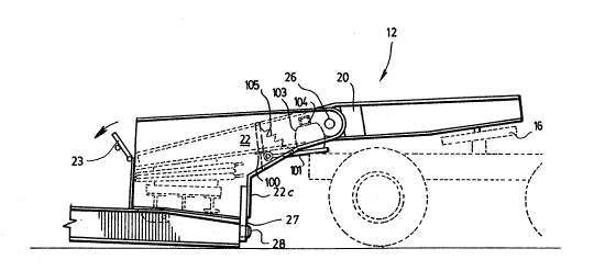
Referring now to Figure 1, the front structure of a trailer
(10) is shown, having an air-lift coupling system ~12)
adaptable to the trailer for joining it to a truck tractor
(14) provided with a fifth wheel ~16).
As shown in Figure 2, and better in Figures 3 and 4, the
air-lift coupling system comprises a lever (20) and a frame
(22) supporting the lever. The lever has at one end a
kingpin ~17), or other end connecting system if one wishes,
for joining the trailer ~10) to a truck tractor. Between
the two ends of the lever ~20), an axle (26) is provided.
.
As shown in Figures 3, 4 and 7, the frame (22) is provided
-- 6 --
. .
,
~` 2~4~
at its base (22c) with a bracket (27) to be mounted on the
front of the trailer (10) and secured thereto by means of
and a lock to releasably lock said engaging portion to said
front end of a trailer, for instance, pins (28) and lever
(29) rotatably mounted about support (31), and having pin
(29a) and being actuated by an air piston (33) connected
opposite said pin (29a). The pin is releasably insertable
into a slot provided in V-shaped structure (10a) being part
of the front structure of trailer (10). Other fastening
devices or systems may be used instead, if desired. The
frame (22) defines a housing for an air-expandable hoisting
bellows (30) to be located under the other end of the lever
(20), opposite the one end having the kingpin (17), and in
space relation thereto, the bellows (30) further includes a
connecting system (32), (34) for releasably connecting said
bellows on said trailer to a pressurized gas-line, generally
air supply for truck tractor (not shown) to inflate or
deflate said bellows, whereby said bellows on expansion
presses against said another end of sald lever (20) and
thereby raises said front end of said trailer. When the
bellows ~30) is deflated, the front end of said trailer is
lowered, as shown in Figure 4.
The housing for the bellows is the preferred embodiment,
since the bellows could also be positioned partly or
completely outside the frame (22). Also, although one
bellows is disclosed, several bellows could be used if
desired.
For security purposesj the frame (22) is also preferably
provided with a lock for locking the lever when the front
end of a trailer is in an upward position; for instance, a
pivotally mounted element (23) (Figure 6) tightly fitting
under the lever (20) at the end of (20b) when the end (20b)
' ., ',' : . '
. -'. ' . ~ ~ ' ' ' , ' :
2 ~ 1 4
is in its uppermost position, thereby any pressure leak
having no effect on the lever engaging the front end of the
trailer in an upward position.
In order to reduce the time to actuate the lever, the
bellows which can be divided into a compressible and an
uncompressible portion, is filled in its uncompressible
portion with a liquid to reduce the compressible portion,
and the amount of air to be introduced for raising the lever
at the end (20b).
The liquid i8 for instance antifreeze, water may be used if
no freezing temperatures are to be encountered. Other
liquid compatible with the nature of the bellows having
suitable freezing point and boiling point may be used.
Better ~hown in Figure 2, having described the principle of
thi~ lever, the lever i~ preferably rectangularly shaped,
and ha~ in ~pace relation to the bellows (30) a space to
confine the bellow8, for instance a plurality of parallel
cro~s bars (42), the rectangular frame for instance is
defined by two longitudinal parallel frames (20) and (20a),
and a front cross bar (44). Still in a most preferred
embodiment, the kingpin (17) is mounted on a plate (46),
itself secured to the longitudinal parallel frames (20) and
(20a) and the front cross bar (44).
The trailer (10) may also be provided with a ramp or other
device or system to support the front end of a trailer, as
shown in Figures 7 and 8. A typical example of such a ramp
is shown at ramp (50). The ramp (50) has a frame having a
top inclined surface (52) acting as a ramp access between
the floor of the trailer and the ground, and for this
purpose, being inclined. It should be noted that the top
.
:-
2 ~ ~1 5 ~ L~
surface and the upper portion of the frame, near the front
end of the trailer stops short to define a leg (54a),
enabling said trailer (10) to rest on said leg, when the
lock (23) is disengaged, i.e. lowered in the case shown, and
the bellows deflated. Preferably as shown in Figures 7 and
8, the frame (54) has sides having the appearance of a
rectangular triangle and being hingedly connected such that
the hypotenuse (56) is resting on the ground, the base (52)
or top may rest inside the front end of the trailer, and a
portion near the right angle is cut off to define the leg
member (54a). This ramp (50) is conveniently mounted on a
bracket (60) secured to the front end of the frame of the
trailer (10). The ramp may also be provided with handles
(62) to swin~ the ramp (50). Said ramp being rotatably
mounted about the bracket (60) by means of pivot (64).
The ramp is generally a set mounted on each side of the
airlit coupling system, but need not be.
The ramp i8 essential in some cases when the displacement of
the bracket (27) and of the bellows is of a relatively short
distance to engage the front end of a trailer.
Referring now to Figures 2, 3 and 4, as it can easily be
seen in a preferred embodiment, the air-lift coupling system
further includes an arm (101) being rotatably mounted, said
arm having mounted thereon bellows (102), (103), said
bellows being secured to a beam (104) itself secured to the
frame (22). The arm (101) is disposed so that it may rest on
the back end of a truck tractor (14 ) (Figure 3). The pivot
for the arm (101) can be easily mounted on the same frame
(22) or auxiliary frame, if desired. The frame (22) i8 also
provided with spring devices such as shown at (105), said
spring devices being mounted either on the frame (22) or
:~ . ; '- '
.. ' . ~ ,
-`~` 20~151~
auxiliary frame such as a H-frame, as shown at (100), to
urge the arm (101) upwardly when the bellows (102), (103)
are not inflated. The bellows (102), (103) are also provided
with a system to feed pressuri~ed gas into said bellows, as
is well known.
OPERATION OF THR SYSTEM TO HOLD THE BRACKET UP
WHEN DISENGAGED FROM A TRAILER
10 When the air-lift coupling system enables lowering of the
front end of a trailer, as shown in Figure 4, the arm or
platform (101) can be easily lowered onto the back end of
the truck trailer (14), thereby maintaining said air-lift
coupling system on said truck and enabling said frame to be
15 kept at some distance from the floor on the road. In order
to support arm (20), air is introduced in bellows (102),
(103). The air in the bellows is urging expansion and
pres3ing the arm (101) againct the back end of the truck
traller (14) and thereby, pushing upwardly the arm (20).
20 When the arm (101) is not required, the air in bellows
(102), (103) is removed and thereby, the spring device (105)
urges the arm upwardly, said arm being thus kept within the
boundaries of said support (22).
25 Although the present invention has been explained
hereinabove by way of preferred embodiments thereof, it
should be pointed out that any modifications to these
preferred embodiments, within the scope of the appended
claims, is not deemed to change or alter the nature and
30 scope of the invention.
- 10 --
~ ,.