Language selection

Search

Patent 2041691 Summary

Third-party information liability

Some of the information on this Web page has been provided by external sources. The Government of Canada is not responsible for the accuracy, reliability or currency of the information supplied by external sources. Users wishing to rely upon this information should consult directly with the source of the information. Content provided by external sources is not subject to official languages, privacy and accessibility requirements.

Claims and Abstract availability

Any discrepancies in the text and image of the Claims and Abstract are due to differing posting times. Text of the Claims and Abstract are posted:

  • At the time the application is open to public inspection;
  • At the time of issue of the patent (grant).
(12) Patent Application: (11) CA 2041691
(54) English Title: OPTICAL PRESSURE TRANSDUCER
(54) French Title: CAPTEUR DE PRESSION OPTIQUE
Status: Dead
Bibliographic Data
(51) International Patent Classification (IPC):
  • G01L 1/04 (2006.01)
  • G01L 9/00 (2006.01)
  • G01N 21/84 (2006.01)
(72) Inventors :
  • GRUDZIEN, CHRISTOPHER P., JR. (United States of America)
  • PANAGOTOPULOS, LOUIS (United States of America)
(73) Owners :
  • GRUDZIEN, CHRISTOPHER P., JR. (Not Available)
  • PANAGOTOPULOS, LOUIS (Not Available)
  • DYNISCO, INC. (United States of America)
  • DYNISCO, INC. (Not Available)
(71) Applicants :
(74) Agent: SWABEY OGILVY RENAULT
(74) Associate agent:
(45) Issued:
(22) Filed Date: 1991-05-02
(41) Open to Public Inspection: 1991-11-03
Availability of licence: N/A
(25) Language of filing: English

Patent Cooperation Treaty (PCT): No

(30) Application Priority Data:
Application No. Country/Territory Date
07/517,827 United States of America 1990-05-02

Abstracts

English Abstract


ABSTRACT OF THE DISCLOSURE

An optical pressure transducer employing input and output
optical fibers defining therebetween an optical path. The
optical path is interrupted by a fixed reflector and a moveable
reflector. The moveable reflector is secured by adjustment
means to the diaphragm that is responsive to pressure being
measured.


Claims

Note: Claims are shown in the official language in which they were submitted.


The embodiments of the invention in which an
exclusive property or privilege is claimed are
defined as follows:

1. A pressure transducer comprising; a body,
an input optical fiber, said body having means for
receiving said input optical fiber, an output optical
fiber, said body having means for receiving said
output optical fiber, a force responsive diaphragm,
means securing the diaphragm to the body at a
position adjacent the optical fibers, a fixed
position reflector, means positioning the fixed
position reflector in the optical path defined
between said input and output optical fibers, a
moveable reflector, and means securing the moveable
reflector to said diaphragm to be responsive to
deflection thereof and positioned to move with
movement of the diaphragm primarily only in a
direction substantially aligned with the optical axis
of at least one of the optical fibers so as to couple
different proportional amounts of reflected light, in
said optical path between said input and output
optical fibers.

2. A pressure transducer as set forth in
claim 1 wherein said input and output optical fibers
are disposed in relative juxtaposition with ends
thereof in the optical path disposed in a common
plane.

3. A pressure transducer comprising; a body,
an input optical fiber, said body having means for
receiving said input optical fiber, an output optical
fiber, said body having means for receiving said
output optical fiber, a force responsive diaphragm,


means securing the diaphragm to the body at a
position adjacent the optical fibers, a fixed
position reflector having a reflecting surface in
line with the axis of said output optical fiber,
means positioning the fixed position reflector in the
optical path defined between said input and output
optical fibers, a moveable reflector, and means
securing the moveable reflector to said diaphragm to
be responsive to deflection thereof and positioned in
said optical path between said input and output
optical fibers wherein said fixed reflector has a
reflecting surface in line with the axis of said
output optical fiber.

4. A pressure transducer as set forth in
claim 3 wherein said moveable reflector has a
reflecting surface in line with the axis of said
input optical fiber.

5. A pressure transducer as set forth in
claim 4 wherein said fixed and moveable reflectors
are disposed at a relative position on the order of
90° to each other.

6. A pressure transducer as set forth in
claim 5 wherein said moveable reflector is supported
at about the central axis of said diaphragm by an
adjusting member.

7. A pressure transducer as set forth in
claim 6 including a light source for establishing an
optical signal in said input optical fiber for
direction to said moveable reflector.


8. A pressure transducer as set forth in
claim 7 including an optical detector for detecting
an optical signal from said output optical fiber as
reflected from said fixed reflector and directed into
said output optical fiber.

9. A pressure transducer as set forth in
claim 8 including means defining predetermined
optical restricting apertures of the respective
fibers and disposed at said common plane.

10. A pressure transducer comprising; a body,
an input optical fiber, said body having means for
receiving said input optical fiber, an output optical
fiber, said body having means for receiving said
output optical fiber, a force responsive diaphragm,
means securing the diaphragm to the body at a
position adjacent the optical fibers, a fixed
position reflector, means positioning the fixed
position reflector in the optical path defined
between said input and output optical fibers, a
moveable reflector, means securing the moveable
reflector to said diaphragm to be responsive to
deflection thereof and positioned in said optical
path between said input and output optical fibers, an
aperture plate secured to the face of said body at a
common plane, said aperture plate having means
defining an input aperture in alignment with the
input optical fiber and an output aperture, in
alignment with the output optical fiber.

11. A pressure transducer as set forth in
claim 10 including a reflector plate disposed over
said aperture plate and having metal pieces defining
said fixed and moveable reflectors.


12. A pressure transducer as set forth in
claim 11 wherein said reflector plate includes
S-shaped flexures interconnecting the moveable
reflector and the fixed periphery of the reflector
plate.

13. A pressure transducer comprising; a body,
an input optical fiber, said body having means for
receiving said input optical fiber, an output optical
fiber, said body having means for receiving said
output optical fiber, a force responsive diaphragm,
means securing the diaphragm to the body at a
position adjacent the optical fibers, a fixed
position reflector, means positioning the fixed
position reflector in the optical path defined
between said input and output optical fibers, a
moveable reflector, and means securing the moveable
reflector to said diaphragm to be responsive to
deflection thereof and positioned in said optical
path between said input and output optical fibers
wherein said input optical fiber is bifurcated to
provide a separate input optical fiber.

14. A pressure transducer as set forth in
claim 13 including a reference reflector surface and
a second output optical fiber, said reference
reflector surface being a fixed surface of the body
disposed in the optical path between the separate
input optical fiber and the second output optical
fiber.

15. An optical transducer comprising a body
and associated diaphragm, said body and diaphragm
defining therebetween an optical sensing space, means
defining an optical path at least in part extending


into said space, said optical path defined by a
plurality of optical fibers, said optical path having
associated therewith means for establishing a light
intensity pattern and means for detecting a modified
light intensity pattern, a fixed position reflector
means disposed in the optical path, a moveable
reflector means disposed in the optical path, and
means for securing the moveable reflector means to
said diaphragm to move with movement of the diaphragm
primarily only in a direction substantially aligned
with the optical axis of at least one of the optical
fibers so as to couple different proportional amounts
of reflected light.

16. An optical transducer comprising a body
and associated diaphragm, said body and diaphragm
defining therebetween an optical sensing space, means
defining an optical path at least in part extending
into said space, said optical path having associated
therewith means for establishing a light intensity
pattern and means for detecting a modified light
intensity pattern, a fixed position reflector means
disposed in the optical path, a moveable reflector
means disposed in the optical path; means for
securing the moveable reflector means to said
diaphragm; and adjusting means for adjusting the
position of said moveable reflector relative to said
diaphragm.

17. An optical transducer as set forth in
claim 15 wherein said means for securing the moveable
reflector includes means for securing the moveable
reflector to the center axis of said diaphragm.


18. An optical transducer as set forth in
claim 15 including means defining a first aperture
for controlling the light pattern directed to the
moveable reflector and means defining a second
aperture for receiving the light reflected from the
fixed reflector.

19. An optical transducer comprising a body
and associated diaphragm, said body and diaphragm
defining therebetween an optical sensing space, means
defining an optical path at least in part extending
into said space, said optical path defined by a
plurality of optical fibers, said optical path having
associated therewith means for establishing a light
intensity pattern and means for detecting a modified
light intensity pattern, a fixed position reflector
means disposed in the optical path, a moveable
reflector means disposed in the optical path, and
means for securing the moveable reflector means to
said diaphragm, wherein said moveable reflector is
disposed in a manner for movement with said diaphragm
in a direction orthogonal to the plane of the face of
the diaphragm so as to couple different proportional
amounts of the intensity pattern as reflected from
the fixed reflector to the associated output
aperture.

20. A method of constructing an optical
transducer including the steps of, providing a body,
providing juxtapositioned passages in the body,
inserting optical input and output fibers in these
passages so that the ends thereof are substantially
flush with the face of the body, providing fixed and
moveable reflectors, defining an optical path between
the input and output optical fibers, and positioning


the fixed and moveable reflectors in a series
arrangement in the optical path between the input and
output optical fibers.

21. A method as set forth in claim 20
including adjusting the position of the moveable
reflector relative to the diaphragm of the
transducer.

22. A pressure transducer comprising; a body,
an input optical fiber, said body having means for
receiving said input optical fiber, an output optical
fiber, said body having means for receiving said
output optical fiber, a force responsive diaphragm,
means securing the diaphragm to the body at a
position adjacent the optical fibers, a fixed
position reflector, means positioning the fixed
position reflector in the optical path defined
between said input and output optical fibers, a
moveable reflector means supporting said moveable
reflector from said diaphragm and including an
adjusting member for adjusting the position of said
moveable reflector relative to said diaphragm.

23. A pressure transducer as set forth in
claim 22 wherein said moveable reflector is disposed
in a manner to move with movement of the diaphragm
substantially in the direction of the optical axis of
at least one of the optical fibers so as to couple
different proportional amounts of reflected light.


24. The pressure transducer of claim 23
wherein said fixed reflector has a reflecting surface
in line with the axis of said output optical fiber.

25. The pressure transducer as set forth in
claim 23 wherein said moveable reflector has a
reflecting surface in line with the axis of said
input optical fiber.

26. A pressure transducer as set forth in
claim 10 wherein said aperture plate is secured to
the face of said body at a common plane.

27. A pressure transducer as set forth in
claim 10 further comprising an adjusting means for
adjusting the position of said moveable reflector
relative to said diaphragm.

28. A pressure transducer comprising; a body,
an input optical fiber, said body having means for
receiving said input optical fiber, an output optical
fiber, said body having means for receiving said
output optical fiber, a force responsive diaphragm
having a face onto which pressure is applied, means
securing the diaphragm to the body at a position
adjacent the optical fibers, a fixed position
reflector, means positioning the fixed position
reflector in the optical path defined between said
input and output optical fibers, a moveable reflector
disposed in a manner to move with movement of the
diaphragm in a direction substantially orthogonal to
the plane of the face of the diaphragm, means
securing the moveable reflector to said diaphragm to
be responsive to deflection thereof and position in


said optical path between said input and output
optical fibers, an aperture plate secured to said
body, said aperture plate having means defining an
input aperture and an output aperture disposed
between said optical fibers and said reflectors.

29. A pressure transducer as set forth in
claim 28 wherein the aperture plate is secured to
said body at a common plane.

30. A pressure transducer of claims 28 or 29
further comprising an adjusting means for adjusting
the position of said moveable reflector relative to
said diaphragm.

31. A pressure transducer as set forth in
claim 14 including a photosensitive device disposed
in the optical path of said second output optical
fiber.

32. A pressure transducer as set forth in
claim 13 wherein said moveable reflector is disposed
in a manner to move with movement of the diaphragm
substantially in the direction of the optical axis of
at least one of the optical fibers so as to couple
different proportional amounts of reflected light.

33. A pressure transducer as set forth in
claim 32 wherein said moveable reflector has a
reflecting surface in line with the axis of said
input optical fiber.


34. A pressure transducer as set forth in
claim 13 further comprising an adjustment means for
adjusting the position of said moveable reflector
relative to said diaphragm.

35. A pressure transducer as set forth in
claim 13 wherein said separate input optical fiber
carries a portion of an input light source directly
to a photosensitive device.

36. A pressure transducer comprising; a body,
an input optical fiber, said body having means for
receiving said input optical fiber, an output optical
fiber, said body having means for receiving said
output optical fiber, a force responsive diaphragm,
means securing the diaphragm to the body at a
position adjacent the optical fibers, a fixed
position reflector, means positioning the fixed
position reflector in the optical path defined
between said input and output optical fibers, a
moveable reflector, and means securing the moveable
reflector to said diaphragm to be responsive to
deflection thereof and positioned in said optical
path between said input and output optical fibers;
and means for adjusting the position of said moveable
reflector relative to said diaphragm.

37. An optical pressure transducer comprising;
a body, an input optical fiber, said body having
means for receiving said input optical fiber, an
output optical fiber, said body having means for
receiving said output optical fiber, a force
responsive diaphragm said diaphragm having a face
onto which pressure is applied, means securing the
diaphragm to the body at a position adjacent the


optical fibers, a fixed position reflector, means
positioning the fixed position reflector in the
optical path defined between said input and output
optical fibers, said optical path having associated
therewith means for establishing a light intensity
pattern, a moveable reflector, means securing the
moveable reflector to said diaphragm to be responsive
to deflection thereof and positioned in said optical
path between said input and output optical fibers,
wherein said moveable reflector is disposed in a
manner to move with movement of the diaphragm
primarily only in a direction substantially
orthogonal to the plane of the face of the diaphragm
so as to couple different proportional amounts of the
intensity pattern as reflected from the fixed
reflector to the associated output fiber.

38. An optical transducer as set forth in
claim 37 including adjusting means for adjusting the
position of said moveable reflector relative to said
diaphragm.

39. A method of constructing an optical
transducer including the steps of, providing a body,
providing juxtapositioned passages in the body,
inserting optical input and output fibers in these
passages, providing a force responsive diaphragm,
providing means securing the diaphragm to the body at
a position adjacent to the optical fibers, providing
fixed and moveable reflectors, said moveable
reflector disposed in a manner to move with movement
of the diaphragm primarily only in a direction
substantially aligned with the direction of the
optical axis of at least one of said optical fibers
defining an optical path between the input and output


optical fibers, and positioning the fixed and
moveable reflectors in a series arrangement in the
optical path between the input and output optical
fibers.

40. The method of claim 39, further comprising
providing an adjusting means for adjusting the
position of said moveable reflector relative to said
diaphragm.

41. The method as set forth in claims 39 or
40, further comprising providing means defining a
first aperture for controlling the light pattern
directed to the moveable reflector and providing
means defining a second aperture for receiving the
light reflected from the fixed reflector.

42. A method of constructing an optical
transducer including the steps of, providing a body,
providing juxtapositioned passages in the body,
inserting optical input and output fibers in the
passages, wherein at least one of said input fibers
is bifurcated to provide a separate input optical
fiber, providing a force responsive diaphragm,
providing means securing the diaphragm to the body at
a position adjacent to the optical fibers, providing
fixed and moveable reflectors, said moveable
reflector disposed in a manner to move with movement
of the diaphragm in a direction substantially aligned
with the direction of the optical axis of at least
one of said optical fibers defining an optical path
between the input and output optical fibers, and
positioning the fixed and moveable reflectors in a
series arrangement in the optical path between the
input and output optical fibers.


43. The method as set forth in claim 42,
further comprising providing an adjusting means for
adjusting the position of said moveable reflector
relative to said diaphragm.

44. The method as set forth in claims 42 or
43, further comprising providing means defining a
first aperture for controlling the light pattern
directed to the moveable reflector and providing
means defining a second aperture for receiving the
light reflected from the fixed reflector.

45. A pressure transducer comprising; a body,
an input optical fiber, said body having means for
receiving said input optical fiber, an output optical
fiber, said body having means for receiving said
output optical fiber, a force responsive diaphragm,
means securing the diaphragm to the body at a
position adjacent the optical fibers, a fixed
position reflector, means positioning the fixed
position reflector in the optical path defined
between said input and output optical fibers, a
moveable reflector, means securing the moveable
reflector to said diaphragm to be responsive to
deflection thereof and positioned in said optical
path between said input and output optical fibers, an
aperture plate secured to the face of said body, said
aperture plate having means defining an input
aperture and an output aperture, said apertures
disposed between said optical fibers and said
reflectors.

46. An optical transducer comprising a body
and associated diaphragm, said body and diaphragm
defining therebetween an optical sensing space, means


defining an optical path at least in part extending
into said space, said optical path defined by a
plurality of optical fibers, a fixed position
reflector means disposed in the optical path, a
moveable reflector means disposed in the optical
path, and means for securing the moveable reflector
means to said diaphragm at substantially a single
point securing area of the diaphragm.

47. An optical transducer as set forth in
Claim 46 wherein said means for securing the moveable
reflector supports the moveable reflector so that it
has a free end disposed in the optical path in
alignment with one of the optical fibers.

48. An optical transducer comprising a body
and associated diaphragm, said body and diaphragm
defining therebetween an optical sensing space, means
defining an optical path at least in part extending
into said space, said optical path defined by a
plurality of optical fibers, a fixed position
reflector means disposed in the optical path, a
moveable reflector means disposed in the optical
path, and means for securing the moveable reflector
means to said diaphragm to provide a free end of the
moveable reflector means in the optical path
substantially in alignment with the optical axis of
one of the optical fibers.

49. An optical transducer comprising a body
and associated diaphragm, said body and diaphragm
defining therebetween an optical sensing space, means
defining an optical path at least in part extending
into said space, said optical path defined by a
plurality of optical fibers, a fixed position


reflector means disposed in the optical path, means
supporting the diaphragm so that the diaphragm
extends fully across the optical path overlying both
optical fibers, and means for securing the moveable
reflector means to said diaphragm at a position
adjacent one of said optical fibers.

50. An optical transducer comprising a body
and associated diaphragm, said body and diaphragm
defining therebetween an optical sensing space, means
defining an optical path at least in part extending
into said space, said optical path defined by a
plurality of optical fibers, a fixed position
reflector means disposed in the optical path, a
moveable reflector means disposed in the optical
path, both said fixed and moveable reflector means
having like reflective surfaces.

51. An optical transducer as set forth in
claim 50 wherein said optical path is absent any
optical grating surface.

Description

Note: Descriptions are shown in the official language in which they were submitted.


2 ~

D0039/7033
D~5D/dpv
1--16--90
0963d

OPTICAL PRESSU~E TRANSDUCER
BACKGROUND OF THE INV~TION
1. Field of the Invention.
The present invention relates in general to pressure
transducers and pertains, more particularly, to a pressure
transducer that is adapted to sense pressure by optical means.
2. Backqround Discussion.
The assignee of the present application presently
manufacturers and sells melt pressure transducers that are
covered by one or more of the fol~owing United ~tates patents:
U.S. Patent No. Issued
3,34~,623 October 31, 1967
3,678,753 July 25, 1972
4,680,g72 July 21, 1987
4,679,438 July 14, 1987
4,702,113 October 27, 19~7
4,712,430 December 15, 1987
4,829,827 May 16, 1989
4,819,487 April 11, 1989
4,858,471 August 22, l9B9
For the most part, these pressure transducer constructions
use a liquid metal filled capillary system. A typical fill
ma~erial is mercury. For some applications, particularly where
toxicity could be critical, mercury filled pressure transducers
may ~e considered somewhat unsafe in operation.


. . . .. , ~ . . ~., .... .: . ~ . . . . , - -.

.. , . .. - . - .. . , . I .

2 ~

Accordingly, it is an object of the present invention to
provide an alternative pressure sensor construction which
eliminates the need for a liquid metal filled capillary
system and which is yet able to operate in harsh, high
temperature/pressure working environments.
Another object of the present invention is to provide an
optical pressure transdllcer which permits the signal
conditioning electronics to be disposed remote to the working
environment without 105s of signal integrity.
A further object of the present invention is to provide an
improved optical pressure transducer that can be constructed in ;-
relatively small size, particularly adapted for essential
retrofit in a standard melt pressure transducer framework.

SUMMARY OF THE INVENTION

To accomplish the foregoing and other objects, features ;~
and advantages of the invention, there is provided an optical
pressure transducer that includes a body for supporting therein
both an input optical fiber as well as an output optical
fiber. The input and output optical fibers are preferably
disposed in relative juxtaposition with their sensing ends
preferably disposed in a common plane and defining therebetween
an optical path. A force responsive diaphragm is secured to

~ - -2-


,.,-, .... . . , .... .~ . .

2 ~ L~

the body at a position essentially adjacent to the ends of the
optical fibers. A fixed position reflector is disposed in the
optical path defined between the input and output optical
fibers. A moveable reflector is also provided. This is
secured to the diaphra~m to be responsive to deflection
thereof. The moveable reflector is also positioned in the
optical path between the input and output optical fibers.
In accordance with further features of the present
invention, the fixed reflector is constructed so that it has a
reflecting surface essentially in line with the axis of the
output optical fiber. Similarly, the moveable reflector has a
reflecting surface that is substantially in line with the axis
of the input optical fiber. The fixed and moveable reflectors
are essentially disposed at a relative right angle to each
other. The movea~le xeflector is preferably supported at about
the central axis of the diaphragm and i.s supported by means of
an adjusting member. A light source e~tablishes an optical
signal in the input optical fiber, while an optical detector
detects an optical signal from the output optical fiber. Means
are provided, preferably in the form of an aperture plate for
defining predetermined optical restricting apertures of the
respective fibers. The aperture plate is secured to the face
of the body at the aforementioned common plane. There is also
provided a reflector plate disposed over the aperture plate


~ . , ~,: . ,. , . ' ~ :
., : "


and having metal pieces defining the fixed and moveable
rPflectors. The reflector plate preferably also includes
S-shaped flexures interconnecting the moveable reflector and
the fixed periphery o the reflector plate.
In an alternate embodiment of the invention described
herein, the input optical fiber is divided to form a bifurcated
separate optical fiber. This separate optical fiber carries a
portion of the input (unmodified) intensity pattern to a fixed
surface of the body of the transducer. The light is reflected
from this surface into a second reference output optical
fiber. This arrangement is for providing feedback to the
conditioning electronics to minimize signal errors externally
induced by microbending of the optical fibers as well as
temperature induced dimensional changes associated with the
transducer body.
In another embodiment of the present invention disclosed
herein, the input optical fiber ls also divided to form a
bifurcated input/output optical fiber. This fiber carries a
portion of the u~modified intensity pattern from the light
source directly to a second photosensitive device. This
arrangement provides feedback to the conditioning electronics
to minimize signal errors due to,light source drift with
time/temperature and photosensitive device thermal effects.


~ -4-


- , , :: . , : : . . : , . . : : :
, - . ., . ,,,. ,.: .: ... ~ ,
:~ ,;: : . . : . . -
: ,, ... . . , , -

~41~ ~

BRIEF DESCRIPTION OF THE DRAWINGS

Numerous other objects, features and advantages of the
inventicn should now become apparent upon a reading of the
following detailed description taken in conjunction with the
accompanying drawings, in which:
FIG. 1 is ~ partial sectional view of the optlcal pressure
transducer of the present invention;
FI~. 2 is a cross-sectional view taken along line ~-2 of
FIG. 1 showing further details in particular of the aperture
plate;
FIG. 3 is a cross-sectional view taken along line 3-3 of
FIG. 1 showing further details in particular of the metal
flexure plate and spacer plate:
FIG. 4 is a partial cross-sectional view of the optical
path in the rest position of the pressure responsive diaphragm;
FIG. 5 is a fragmentary cross-sectional view similar to
that illustrated in FIG. 4 but showing somewhat by exaggeration
the position of the reflectors upon deflection of the diaphragm;
FIG. 6 illustrates the input Iight intensity pattern;
FI~. 7 illustrates the output intensity light pattern;
FIG. 8 illustrates a second embodiment of the present
invention employing a transducer construction with main optical
path similar to that illustrated in FIG. 1 but also including a
further reference portion of the transducer;

. 5


- . . . . ;: .. , ; . ~ , . . .

:: ; ~ . . ~ . : ,. ,- -- .. , ~ . . . .. .
.,. ... . .,. ~, . . . .

~ , . .. ~ . .. . I .

2 ~

FIG. 9 is a plan view of the specific construction of the
reflector plate as in accordance with the disclosed embodiment
herein;
FIG. lo illustrates a third embodiment of the present
invention; and
FIG. 11 is a plot of output voltage versus deflection used
in explaining the adjustments made in accordance with the
transducer of the present invention.

DETAILED DESCRIPTION

Reference has been made herein before to several earlier
patents of the assignee of the present invention. These melt
pressure transducer constructions genexally employ an elongated
frame and in the past when using a fil:led capillary system, a
diaphragm or coupler is employed at the snout end of the frame
and a sensing head appears at the opposite end of the frame~
The sensing head may employ strain gages or the like for
essentially converting a sensed pressure into an electrical
signal.
- ~ow, in accordance with the present invention as
illustrated herein, a deflection at the diaphrasm is sensed
optically and this, thus, allows the sensing electronics to be
remote from the working environment, or in other words, the
place where the diaphragm or coupler is arranged.

~ -6-


,~, . ,:: ..... .. : , ~ . , :

, : . ~ :. : ; .: , .:

2 ~ 9 ~

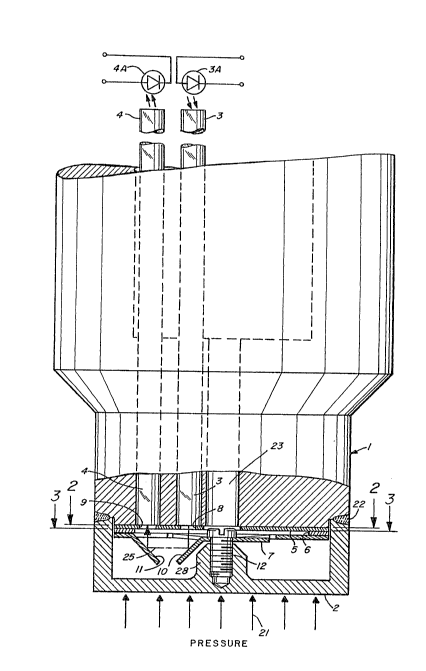
Now, with respect to the embodiment of the inventionlllustrated in FIGS. 1-3 herein, the optical pressure
transducer is considered as being comprised of a body 1 that is
preferably constructed of a rigid metal and a force summing
diaphragm 2. As noted in FIG. 1, the arrows 21 illustrate the
direction in which pressure is applied to the diaphragm 2. It
is this pressure that is being sensed by the optical pressure
transducer of the invention.
The diaphragm 2 may be constructed of a metal material.
Examples of material include stainless steel or a nickel
chromium iron a:lloy. The diaphragm 2 may be welded to the
transducer body 1 such as by means of electron beam welding.
This is illustrated in FIG. 1 at 22.
Within the body 1 are disposed the optical fibers 3 and
4. FIG. 1 illustrates these optical fibers extending through
the body 1. The optical fibers include an input optical fiber
3 which at its top end receives light from a li5ht source such
as the illustrated light emitting diode 3A. The lower end of
the optical fiber 3 is secured in position flush with the lower
end face of the body 1. This is along a plane that is the
plane where a~ the cross-section 2-2 is taken in FIG. 1.
The output optical fiber 4 at its lower end is also
dlsposed in a fixed manner at this same plane. The top end of
the fiber 4 is positioned so as to direct output light to a
photosensitive element such as the illustrated photodiode 4A.

~ -7-


... , . - .:: . ~.. . ".

2 ~


The transducer body 1 is also provided with a centrally
disposed passage ~3. This passage is adapted to receive a
member such as a screwdriver 4 turning the adiusting screw 12.
This operation is discussed in further detail hereinafter.
In FIG. 1, a broken arrow 25 illustrates an optical path
between the fibers 3 and 4. It is this optical path that is
interrupted by the reflectors 10 and 11 to be described in
further detail hereinafter. This optical path is controlled by
a certain masking plate, also identified herein as ~he
aperture plate 5 illustrated in, for example, FIGS. 1 and 2.
This aperture plate 5 includes slot~like apertures 8 and 9.
The light emanating from the sensor end of the input optical
fiber 3 is masked by an input apertuce 8 which modifies the
light intensity pattern coming from the optical fiber 3. This
pattern is reflected down onto the moveable reflector 10 which
is connected to the force summing diaphragm 2, by means of the
adjusting screw 12.
The modified intensity pattern (optical path 25) is
reflected from the moveable reflector 10 to the fixed reflec~or
11 and from there through the output aperture 9 into the output
optical fiber ~. The output aper~ure 9 blocks a proportional
amount of the modified intensity pattern preventing it from
entering the output optical fiber 4. The initial amount
blocked from the end of the output optical fiber 4 is


:, : ,, . , -: .-. - ~ -


. .


determined by the initial vertical position of the moveable
reflector 10. Application of pressure to the face of the
diaphragm 2 causes the moveable reflector 10 to displace
vertically changing the proportional amount of the modified
intensity pattern entering the receiving end of the output
optical fiber 4. This change is detected at the output end of
the output optical fiber 4 by a photosensitive device such as
~he illustrated photodiode 4A.
As indicated previously, upon application of pressure to
the diaphragm 2, the moveable reflector 10 is displaced. This
is illustrated in, for example, FIG. 5. The initial position
of the moveable reflector 10 is shown in phantom outline, while
the displaced position of the moveable reflector 10 is shown in
solid outline. A comparison between FIGS. 4 and 5 clearly
illustrates the manner in which the proportional amount of the
.intensity pattern is permitted to either be blocked or passed
to the output optical fiber 4.
For example, in FIG. 4 there is a far smaller proportion
of the reflected signal that enters the optical fiber 4. In
FIG. 5, on the other hand, there is a substantially larger
proportion of the signal that is passed into the output optical
fiber 4.


.... ... . . . ..

.... .: : ;.:: ... .. .. : .. .-: : . .:

; : :: . . :,
,, . . .. - . . ~.. .. . .
,: . ~: , -

2~69~

The optical flbers 3 and 4 may each be a metal coated
silica clad, silica core, multi-mode, stepped index optical
fiber. These optical fibers may be epoxied into holes provided
in the transducer body using a high temperature (600 C)
epoxy. The ends of the optical fibers 3 and 4 and a front face
of the body 1 are polished to a mirror finish, along the plane
defined by the cross-section 2-2 in FIG. 1. This provides a
smooth mounting surface and flat optically clear fiber ends.
The smooth mounting surface is for receiving a series of plates
and defining, for example, the apertures and reflectors. These
various plates are illustrated in FIGS. 2, 3, and 9.
FIG. 2 illustrates the aperture plate 5. This may be a
photochemically etched metal aperture plate which is placed on
the polished surface of the body in a :Eashion to ensure the
alignment of the two apertures 8 and 9 with relationship to the
optical fibers 3 and 4. This position is illustrated in FIG.
2. Once the aperture plate 5 is in position, then it may be
resistance welded to the transducer body 1.
Next, there is provided a photochemically etched metal
spacer plate 6. This is illustrated in FIG. 3. This is also
aligned with the aperture plate 5 and is resistance welded
theretb. Alignment tabs, holes or the like may be pro~ided for
proper alignment of these various plates.


--10--


- . . . .................... , - , , . - , .
. . . .. . .

2 ~


Next, reference is made to FIG. 9 which illustrates a plan
view of the formed metal flexure plate. This is a
photochemically etched plate that has a reflective coating
thereon. Again, this plate is aligned in a manner so that the
moveable reflector 10 and the fixed reflector 11 are aligned
parallel to the apertures 8 and 9 in the aperture plate 5. The
flexure plate 7 is then resistance welded to the spacer plate
6. Reference is made hereinafter to further details of the
flexure plate 7, particularly as it relates to the operation of
the adjusting screw 12.
In the transducer illustrated in FIG. 1, at the tops of
the fibers 3 and 4 the ends of the fibers may be clea~ed at the
appropriate length, polished if required, and inserted into a
standard source and standard detector i-or a futlctional check.
With the aid of the standard source/del:ector, the course offset
adjustment screw 12 with a small amount of high temperature
epoxy disposed on the threads thereof is adjusted to set the
initial vertical position of the moveable reflector 10 to
~chieve an appropriate output settïng from the standard
source~detector with its associated electronics. The epoxy on
the course offset adjustment screw 12 is allowed to cure to
hold the screw 12 in place.
Now, with regard to FIG. 6, there is illustrated therein
an input intensity pattern P-l that exits from the input
optical fiber through the input aperture 8. As also

--11--


- , ~
-: . . , - ,: ..
,, -~: . , . , .: .
. .: . -. . :
, ~, ~:. . :: , . : . .

: :: : ., . : ,,

2~5~ ~

illustrated in FIG. 4, the input intensity pattern P-l is the
one that is at the output of the aperture 8 and is the pattern
that is directed to the moveable reflector lo.
FIG. 7 shows the proportional amount of the modified
intensity pattern that couples through the output aperture 9
and enters the output optical fiber 4 after the appropriate
course offset adjustment screw setting has been made. In FIG.
4, for a normal rest position of the diaphragm this is
illus~rated as the intensity pattern P-2. Also refer to FIG.
7.
In operation, the unmodified light intensity pattern
emitted from the light source travels through the input optical
fiber 3 to the input aperture 8 exiting as the modified
intensity pattern illustrated in FIGS. 4 and 6. This intensity
pattern is reflected down onto the moveable reflector 10 and
across to the fixed reflector 11 and from there up to the
output aperture 9. The output apertur~3 9 masks an appropriate
proportion of the modified intensity pattern as shown in FIGS.
4 and 7, for exam~le, and, therefore, the amount of light
entering the output optical fiber 4 is masked.
Vertical displacement of the mo~eable refle~tor 10, as
illustrated in FIG. 5, proportionally increases the amount of
light intensity pattern entering the output optical fiber 4,
and, thus, also the amount of light that is coupled to the

-12- :


",.~.

2 ~

photodetector 4A. The initial vertical position and the range
of the vertical displacement of the moveable reflector 10 is
selected so that the minimum non-linearity of the modified
intensity pattern is achieved. This occurs symmetric to the
central peak of the modified intensity pattern. In this
regard, refer to FIB. 5 for an illustration of the proportional
increase in the intensity pattern, identified in FIG. 5 as a
pattern P-3 exiting into the output optical fiber 4.
As illustrated in FIGS. 3 and 9, the reflector plate 7 is
constructed so that the moveable reflector 10 is attached to
the fixed peripheral portion of the plate 7 by means of
integral S-shaped flexures 26. There are four such S-shaped
flexures illustrated in FIG. 9. Thes~ flexures provide support
for and permit parallel motion of the moveable reflector 10 in
a direction perpendicular to the plane of the plate 7.
During the assembly process, the S-shaped flexures 2fi are
deformed slightly, at the attachment points on the fixed
portion of plate 7, biasing the position of the moveable
reflector plate towards the aperture plate 5.
Now, reference is made to FIG. 11 for an illustration of
the characteristic conditioned ~photosensitive device and
associated electronics) DC (direct current) voltage output
curve, as a function of the moveable reflector displacement. A
clockwise adjustment (tightening) of the calibration screw 12

-13-


: ' ;: ::, .: ' ' ' ., "~
. ,' ' ,; :: ., - .'' ': '`~'

2 ~

eng~ges the scxew into the threads of the post 28. Then, the
bottom of the screw head engages the base of the moveable
reflector 10 (the area around the clearance hole 29), indicated
as point A on the operating curve.
Continuous clockwise adjustment of the calibration screw
12 gradually moves the moveable reflector 10 towards the
diaphragm 2 generating tension in the S-shaped flexures 26.
This orces the base of the moveable reflector 10 up against
the bottom of the screw head as illustrated in FIG. 1.
As indicated previously, the high temperature epoxy is
applied to the screw threads as well as the underside of the
screw head prior to insertion through the clearance hole 29 in
the moveable reflector 10 and engagement with the threads in
the diaphragm post 28. Also, when the epoxy cures, it locks
the screw in the diaphragm post as wel:L as locking the moveable
reflector 10 to the underside of the screw head.
Before the epoxy cures, however, the calibration screw 12
is adjusted clockwise varying the output voltage through point
B in the curve of FIG. 11 ~corresponding to the position where
the base of the moveable reflector 10 and the base of the fixed
reflector 11 are co-planer, yielding the maxim~m voltage
output) to point C, the course O-pressure setpoint. point C or
O-pressure voltage output, falls at the bottom end of the
linear voltage output to deflection operating range of the

-14-


2 ~

optical sensor, and is the closest position of the moveablereflector 10 to the diaphragm post. Again, in FIG. 11 note the
linear range between points C and D on the curve.
It is furthermore to be noted that the tension generated
by the S-shaped flexures 26 on the calibration screw 12
transmitted to the diaphragm post and diaphragm 2 is small in
comparison to the opposing force generated by the diaphragm
itself.
After the epoxy on the screw 12 cures, this locks the
moveable reflector 10 at a position indicated by point C on the
operating curve. Pressurs generated deflection (deflection
fixed for all pressure ranges at .001 + .OoO~ inches) of the
highly elastic metal diaphragm 2, towards the aper~ure plate 5,
causes the maveable reflector 10 to move toward the aperture
plate 5 to a position shown as point D on the operating curve,
or span (full scale) voltage output. Release o pressure
returns ~he moveable reflector 10 to t:he initial starting
position shown as point C on the operating curve.
Accordingly, by proper adjustment of the screw 12, the
position of the moveable reflector plate is set up so that it
can carry out a full range of pressure detection. Furthermore,
this range, as noted by the diayram of FIG. 11, is a linear
proportional range.


-15-


. ' " . .'. '.~' ", . ' ~ ' . '.

2~ 6~1

Reference is now made to FIG. 8 for an alternate
embodiment of the present invention. In FIG. 8, like reference
characters are used to identify parts previously associated
with the first embodiment of the invention such as the one
illustrated in FIG. 1. Thus, in the embodiment of FI~. 8 there
is illustrated the optical fibers 3 and 4 as well as the
reflectors 10 and 11. However, in this embodiment the input
optical fiber is divided to form a bifurcated fiber that also
includes essentially a separate input optical fiber 13. This
bifurcated input optical fiber 13 carries a portion of the
input unmodifiecl intensity pattern which is directed to a fixed
surface 30 of the transducer body 1. This light is reflected
from this surface 30 into a second reference output optical
fiber 14. A proportional amount of the reflected light is
detected at the output end of the reference optical fiber 1~ by
a photosensitive device such as the illustrated photodiode 4B.
The combination of the light source, bifurcated input optical
fiher 13, and fix~d reflective surface 30 provide a feedback
arrangement for controlling certain detection signals
associated with the transducer. This feedback arrangement
coupled to the conditioning electronics (not shown) minimizes
signal errors externally induced by microbending of the optical
fibers, and temperature induced dimensional changes in the
mechanics of the transducer body 1.

-16-


-... : . . ~-.; .............. ;, . . . .
, ,.~, . - .


FIG. 10 illustrates still a further embodiment of the
present in~ention. Again, ln FIG. 10 the same reference
characters are used to identify similar parts previously
described in association with FIGS. 1 and 8. In the embodiment
of FIG. 10, the input optical fiber 3 is also divided to form a
bifurcated input/output optical fiber 33. This bifurcated
input/output optical fiber 33 carries a portion of the
unmodified intensity pattern from the light source directly to
a second photosensitive device such as the illustrated
photodiode 4C. The combination of the input optical fiber, the
bifurcated fiber and the additional photosensitive device
provide a feedback arrangement to the conditioning electronics
to minimize signal errors due to light source drift with
time/temperature and photosensitive device thermal effects.
~icrobending of the fiber is not addressed in this particular
configuration.
Having now described a limited number of embodiments of
the present invention, it should now be apparent to those
skilled in the art the numerous other embodiments and
modifications thereof are contemplated as falling within the
scope of the present invention as defined by the appended
claims.


-17-

Representative Drawing
A single figure which represents the drawing illustrating the invention.
Administrative Status

For a clearer understanding of the status of the application/patent presented on this page, the site Disclaimer , as well as the definitions for Patent , Administrative Status , Maintenance Fee  and Payment History  should be consulted.

Administrative Status

Title Date
Forecasted Issue Date Unavailable
(22) Filed 1991-05-02
(41) Open to Public Inspection 1991-11-03
Dead Application 1995-11-02

Abandonment History

There is no abandonment history.

Payment History

Fee Type Anniversary Year Due Date Amount Paid Paid Date
Application Fee $0.00 1991-05-02
Registration of a document - section 124 $0.00 1991-10-25
Maintenance Fee - Application - New Act 2 1993-05-03 $100.00 1993-04-21
Registration of a document - section 124 $0.00 1994-02-04
Maintenance Fee - Application - New Act 3 1994-05-02 $100.00 1994-04-26
Owners on Record

Note: Records showing the ownership history in alphabetical order.

Current Owners on Record
GRUDZIEN, CHRISTOPHER P., JR.
PANAGOTOPULOS, LOUIS
DYNISCO, INC.
DYNISCO, INC.
Past Owners on Record
None
Past Owners that do not appear in the "Owners on Record" listing will appear in other documentation within the application.
Documents

To view selected files, please enter reCAPTCHA code :


To view images, click a link in the Document Description column. To download the documents, select one or more checkboxes in the first column and then click the "Download Selected in PDF format (Zip Archive)" or the "Download Selected as Single PDF" button.

List of published and non-published patent-specific documents on the CPD .

If you have any difficulty accessing content, you can call the Client Service Centre at 1-866-997-1936 or send them an e-mail at CIPO Client Service Centre.


Document
Description 
Date
(yyyy-mm-dd) 
Number of pages   Size of Image (KB) 
Description 1991-11-03 17 721
Drawings 1991-11-03 6 236
Claims 1991-11-03 15 677
Abstract 1991-11-03 1 17
Cover Page 1991-11-03 1 30
Representative Drawing 1999-07-27 1 28
Correspondence 1994-09-22 1 26
Fees 1994-04-28 1 63
Fees 1994-04-26 1 60
Fees 1993-04-21 1 48
Fees 1994-09-16 2 68