Note: Descriptions are shown in the official language in which they were submitted.
- 2042043
MOTOR VEHICLE 2~TI-THEFT DEVICE
This invention relates to anti-theft devices for locking
onto a car steering wheel to prevent or limit its movement.
Vehicle anti-theft devices are known in the form of a
steering immobiliser bar having means by which it can be
locked onto a vehicle steering wheel in a position in which a
part of the bar projects from the wheel so that its movement
is obstructed by encounter of the bar with a fiY~ed part of
the vehicle.
Some of the devices of that form comprise a bar in two
telescopically slidable sections which have retaining hooks
for engagement with diametrically opposed portions of a
steering wheel rim. In order to fit the device, the bar is
positioned against the steering wheel and then extended to
bring both retaining hooks into engagement with the wheel
rim, and the bar sections are then locked together (see e.g.
United Kingdom Patent 1127524). The nature of these
manipulations deters some drivers from making habitual use of
such a device when leaving their cars. Moreover there is a
risk of the devices being locked without being properly
engaged with the steering wheel.
United States Patent No 4134282 discloses a steering
immobiliser comprising an L-shaped member with a fastening
device fitted near the junction of the two limbs of the L.
The immobiliser is designed for fastening onto a steering
wheel rim at the top of the wheel so that one limb of the
L-shaped member eY~tends downwardly across the wheel while the
other limb eY~t~nds over the wheel and overlaps the
- 2042043
-
2 20080-343
top edge of the dashboard or instrument panel. An immobiliser of
this deslgn has merely to be bodily placed in correct position on
the steerlng wheel before belng fastened. However thls advantage
ls achleved at the cost of less versatlllty. The form and
dlmenslons whlch the lmmobillser must have ln order that lt can be
fitted in the intended manner would make lt unsulted to more than
a llmlted range of motor car models. Moreover, ln order that the
lmmoblllser can be fltted to flat as well as to dlshed steerlng
wheels, provlslon has to be made for movlng the fastenlng devlce
from one posltlon to another on the L-shaped member. A further
dlsadvantage ls that when the lmmoblllser ls fltted to a flat
steerlng wheel a llmb of the L-shaped member can be used as a long
lever arm to sub~ect the lmmoblllser to very strong forces whlch
may deform or break lt.
The foregolng dlscusslon of prlor art auxlllary antl-
theft devlces comprlsing a steerlng lmmoblllser exposes a problem
faclng deslgners of such products. The problem ls to design a
device whlch ls suited to a wlde range of dlfferent car models,
whlch ls slmple to flt ln worklng posltlon, whlch ls dlfflcult to
neutrallse, and whlch ls reasonably compact. Compactness ls ln
practlce quite lmportant, not only from the standpolnt of car
users, who flnd some of the commerclally avallable products
cumbersome and lnconvenlent to stow ln the vehlcle, but also from
the marketing standpolnt, glven the appreclable cost of good
quallty, attractlve packaglng.
The present lnventlon contrlbutes to a solutlon to thls
problem.
Accordlng to the present lnventlon, there ls provlded an
2042043
-
3 20080-343
antl-theft device for preventing theft of a vehlcle comprlslng a
rlgld steerlng lmmoblllser bar lncludlng a fastenlng means; sald
fastenlng means ln operatlon belng adapted to detachably and
lockably surround a portlon of a vehicle steerlng wheel rlm ln a
posltlon such that an opposlte free end portlon of the bar
pro~ects from the wheel to obstruct steerlng by encounter wlth a
fixed part of the vehlcle, characterlzed ln that the fastenlng
means ls located at one end of the sald bar and the bar extends
from that fastenlng means along a path whlch undergoes directlonal
change such that the bar can brldge over a steerlng wheel hub
whlch pro~ects through the front plane of the steerlng wheel rlm,
and pass through the wheel at a posltlon beyond that hub, so that
a sald free end portlon of the bar pro~ects from behlnd the wheel.
It has been found that the sald dlrectlonal change
feature makes lt posslble to provlde an antl-theft devlce whlch
has a very advantageous comblnatlon of propertles. In partlcular,
lt ls posslble to reallze a greater versatlllty of use for glven
overall dlmenslons of the devlce. In regard to versatlllty,
conslderatlon ls here glven to the capaclty of the devlce to be
fltted ln dlfferent orlentatlons relatlve to a steerlng wheel, and
to the varlety of steerlng wheel deslgns and drlvlng compartment
lay-outs whlch can be catered for by a devlce of glven shape and
dimensions.
It ls self-evldent that a devlce accordlng to the
lnventlon can be fltted not only to steerlng wheels havlng a hub
whlch pro~ects through the front plane of the wheel rlm, but also
to flat and dlshed steerlng wheels ln whlch the top of the hub
lies ln or behlnd that plane.
2042043
3a 20080-343
The prlnclple of the directlonal change feature ls
lllustrated ln Flg. 1 of the accompanylng drawings, whlch flgure
ls purely dlagrammatlc. The flgure represents ln broken llnes a
vehlcle steerlng wheel W. FP is the front plane of the wheel rim.
The hub H of the wheel pro~ects
B
2Q~0~3
through this front plane. An anti-theft device comprises a
bar 2 at one end of which there is a fastening means 3 by
which the device can be locked onto a portion of the rim of
the steering wheel. From the fastener 3 the bar follows a
path which undergoes directional change so that the
anti-theft device can be fitted in a position as shown in
which the bar bridges over the hub H and passes through the
wheel at a position beyond the hub. A free end portion of
the bar projects from behind the wheel. The direction in
which this free end portion projects depends on another
feature of the bar shape as hereafter referred to.
It will be apparent that the range of hub geometries
which can be bridged depends in part on the height = of the
central portion of the bridge formed by the device when it is
fitted to a steering wheel of a given diameter and the top
face of the bar is in contact with the wheel rim at a
position diametrically opposecl to the fastening means, and in
part on the eYtent of the variations (if any) in the bridge
height which occur when the device is fitted to steering
wheels of the different diameters which are to be found in
practice. ~-
In preferred embodiments of the invention the pathfollowed by a first portion of the bar, e~tending from the
fastening means, is such that it forms a bridge whose central
height is at least 3 cm, such height being measured from a
straight notional base line eYtending from the a~is of the
wheel rim receiving passage through said fastening means to a
point on the bar which is at a straight line distance of 36
cm from that aYis. The dimension 36 cm is taken as an
approY~imate mean value of the commonly encountered steering
wheel diameters. In the diagrammatic Fig. 1, the a~is of the
wheel rim receiving passage through the fastening means
2042043
runs perpendicularly to the plane of the drawing and is
represented by the point a. Eor convenience, the axis of the
wheel rim receiving passage through the fastening means is
hereafter alternatively referred to as "the fastener a~is".
Anti-theft devices complying with the foregoing shape
condition are particularly suitable having regard to the
range of steering wheel sizes and designs to be found in most
of the present day volume production motor cars.
In preferred embodiments of the invention, the path of
the bar undergoes a directional change for forming a said
bridge and then undergoes a reverse directional change so
that when the anti-theft device is fitted to a steering
wheel, the free end portion of the bar is nearer to the rear
plane of the steering wheel rim than would otherwise be the
case (i.e. in the absence of the reverse directional
change). It has been found that this reverse directional
change feature additionally promotes the object of making a
steering immobiliser which is suitable for use in a wide
variety of car models yet which is of reasonably compact form.
The bar 2 represented in full line in Fig. 1 eYhibits
this reverse directional change feature, 2a being the free
end portion of the bar. The device can be fitted to a
steering wheel of a given car with the free end portion
projecting from the top, bottom or one side of the wheel,
depending on the positioning of adjacent fi~ed parts of the
car. For eYample, the device can be secured in a position
such that steering is prevented by abutment of the said
projecting free end portion of the bar against the
windscreen, the dashboard, the driver's door or seat, or any
person occupying that seat.
6 2~ ~2043
-
It is particularly advantageous for a free end portion of
the bar remote from the fastening means to be substantially
straight and for the bar to undergo a said reverse
directional change such that when the immobiliser device is
in position on a steering wheel and the top face of the bar
is in contact with the steering wheel rim at a position
diametrically opposite the fastening means, the said free end
portion of the bar makes with the rear plane of the steering
wheel rim an included angle (angle a in Fig. 1) of between
0 and 20. The said free end portion of the bar is
preferably parallel or substantially parallel with said rear
plane. In the case that said angle ~ is not zero, the said
free end portion of the bar may extend forwardly or
rearwardly from that rear plane. In the case of any such
immobiliser device, its overall length should preferably be
such that when fitted to a steering wheel as just described,
the end portion of the bar which projects from behind the
steering wheel rim has a length of at least 15 cm. Given
that the preceding part of the bar should be long enough to
bridge the diameter of the larger steering wheels commonly to
be found in conventional volume production cars, the device
preferably has an effective overall length (measured along a
straight line from the fastener axis to the remote end of the
bar) of at least 53 cm. However, the versatility of the
immobiliser and of course the convenience with which it can
be handled and stowed, is adversely affected by excessive
length. For suiting a wide variety of cars, it is
unnecessary for the said effective overall length of the
device to exceed 60 cm.
The invention includes devices wherein the bar is shaped
so that the anti-theft device can be fitted to a car steering
wheel in a position in which it is locked onto a bottom
region of the steering wheel rim and the free end portion of
7 2042043
. . .
the bar, which projects from behind the wheel rim, projects
forwardly towards the vehicle windscreen and overlaps the top
of the car instrument panel or dashboard. The free end
portion of such a bar can for eY~ample follow a path 2b as
shown in broken line in Fig 1. In the absence of a reverse
directional change in the path of the bar, the device cannot
have quite such a high versatility in relation to its size
There are vehicles for which an immobiliser designed to
co-operate with the top of a vehicle instrument panel or
dashboard would be unsuitable, for eYample because the
vehicle's instrument dials are located on a pod which would
not prevent the steering wheel from being turned with the
immobiliser attached. Moreover the shape of the device tends
to make it less conveniently stowable. Nevertheless, devices
having a bar without the reverse directional change, like
other devices according to the invention, are easy to fit
and, by virtue of the passage of the bar over the wheel hub
and through the wheel, there is little or no risk of the
immobiliser being rendered ineffective by force, using the
bar itself as a lever.
The bar of a device according to the invention may for
eYample be formed by a metal strip or rod.
The fastening means for securing the anti-theft device to
the rim of a steering wheel can for eY~ample be in the form of
a cuff having hingewise connected parts for closing around a
portion of such a rim and a lock mechanism whereby the cuff
can be locked in its closed condition. The lock mechanism
can be of combination or key-operated type.
~ 8 20.~12 0~3
Certain specific forms of steering immobiliser according
to the invention are represented in Figs. 2 to 6 of the
accompanying drawings, which will now be referred to. In
these drawings:
Figs. 2 and 3 are perspective views of one form of
anti-theft device according to the invention, secured to a
car steering wheel;
Fig 4 shows the interior details of the fastening means
of that device;
Fig. 5 shows another form of anti-theft device according
to the invention, secured to a car steering wheel; and
Fig 6 is a side elevation of the device shown in Fig 5
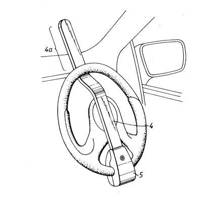
The device shown in Figs. 2-4 comprises a rigid bar 4
having a fastener 5 secured to one end thereof. The bar is
formed by a metal strip which at some distance from the
fastener is bent first in one direction and then in the
opposite direction in planes normal to the faces of the strip
and parallel with its longitudinal axis. The position and
extent of the first bend (the bend which is nearer to the
fastener) is such that the bar can bridge over the hub
portion of a steering wheel and pass through the wheel as
shown in Figs. 2 and 3. The position and extent of the
reverse bend is such that a free end portion 4a of the bar
projects from behind the steering wheel rim in a plane which
is nearly parallel with the plane of that rim. This
particular illustrated device has an effective overall length
(measured as hereinbefore referred to) of 53 cm. The
beginning of the first bend in the bar is approv~imately 23 cm
- from the fastener avis; the second bend ends at a position
which is within a distance of 38 cm from such a~is.
2042043
g
As shown in Fig. 4, the fastening means 5 comprises a
base part 6 and a hinged cover 7 The base part 6 is secured
to one end of the bar by a lock barrel 8 which e~tends
through an aperture in the barrel, and a nut 9 which is
screwed onto the barrel. The lock barrel carries a
spring-loaded latching element 10. The cover carries a
keeper 11 which projects from the inside face of the cover.
The device is fitted by threading the remote end portion of
the bar through the steering wheel, positioning the base part
of the locking device over the front of the wheel rim and
then hinging the cover into closed position over the rear
side of the wheel rim so that the rim is enclosed by the
locking device. As the cover moves into its closed position
the keeper 11 momentarily depresses the latching element 10,
which then springs back into its projecting position, behind
a collar 12 of the keeper. The cover cannot be opened
without a key. In order to remove the device, the key is
inserted into the lock barrel from the front face of the base
part 6 of the locking device. Turning of the key causes the
lock barrel to rotate ~against the action of a spring, which
is not shown) so that the keeper 11 swings out from beneath
the collar 12 of the keeper. The cover can then be hinged
open. A torsion spring can be incorporated at the hinge of
the cover so that it is biased into its open position.
It is recommended that the metal strip 4 be clad with
with plastics material.
Fig. 2 shows the bar secured to a car steering wheel with
the free end portion of the bar projecting upwardly so that
it will prevent steering by abutting against the windscreen
or the dashboard or the driver's door, depending on the
geometry of the driving compartment of the car. Fig.3 shows
20~2~
the device secured to a car steering wheel with the free end
portion of the bar projecting in a generally downward
direction so that it will abut against the driving seat or
any person occupying it and attempting to drive the car.
Figs. 5 and 6 show an anti-theft device according to the
inventlon comprising a bar 14 having a fastening means 15
secured to one end thereof. The bar is constituted by a bent
metal strip 16 sandwiched between layers 17, 18 of a plastics
material. The fastening means 15 is identical to the
fastening means 5 of the anti-theft device shown in
Figs. 2-4. The bar is bent in one direction in planes normal
to the top and bottom faces of the bar and parallel with its
longitudinal axis. The position and extent of the bend is
such that the bar can bridge over the hub portion of a car
steering wheel and pass through the wheel as shown in Fig 5.
The device is intended for mounting as shown with the free
end portion 14a of the bar prc,jecting over the top of the car
instrument panel. For a device intended to be mounted in
this manner it has been found to be suitable for the bar to
have substantially straight portions joined by a bend, the
lengths of those straight portions and the geometry of the
bend being as follows;
(i) length of straight portion adjacent the fastener:
23 cm
(ii) length of straight free end portion of the bar:
15 cm
(iii) geometry of the bend: such that the two straight
portions make an included angle (angle ~ in
- Fig. 6) of 150 and the effective overall length of
the device (length "L" in Fig. 6) is 46 cm.
~U~204~
These data are by way of e~ample. They can be varied while
still achieving a similar effect. But preferably the said
data (i) - (iii) are in any case within the following ranges:
(i) from 15 to 30 cm; (ii) frc,m 10 to 25 cm; (iii) angle
from 135 to 165 and overall length "L" from 40 to 56 cm.
Variations of the shape of the bar shown in Figs. 5 and 6
are possible. For eY~ample the portions which are shown
straight could be curved to scme eY~tent.