Note: Descriptions are shown in the official language in which they were submitted.
PUSH BUTTON FOR A SELF-OPENIN~ UMBRELLA
This invention relates to umbrellas. More
particularly, this invention relates to a control push
button for an automatic umbrella.
In one conventional automatic umbrella, and
as shown in Figs. 11-14, a spring loaded latch arm A
is pivotally connected to the bottom end of a hollow
centerpost C fixed to an umbrella handle B. A push
button E is located in push button hole D at one side
of the handle B. Motion of the spring loaded latch
arm A is controlled by depressing the push button E.
The configuration of the conventional push
button hole D is designed to match the configuration
of the conventional push button E to allow assembly of
the push button with the handle B. The outside of the
push button E is stepped, as shown in Figs. 12-14, so
that the push button E is supported by the interior
surface of the handle's wall to prevent the push
button from escaping when the push button is inserted
into the push button hole D from inside the handle.
Hence, and when the push button E is depressed during
--2--
use, it needs the edges of the hole D in the wall of
the handle B to support the push button and to prevent
the push button from escaping or tilting, as shown in
Figs. 13 and 14. However, and since the wall of the
handle B is relatively thin, during repeated use there
may be wear on the handle hole D which may adversely
affect subsequent use of the latch arm A that controls
automatic opening of the umbrella. Another trouble-
some problem also occurs with the conventional push
button E. When assembling the umbrella, the push
button E must first be placed into the push button
hole D of the handle B from the interior of the handle
B, and thereafter the hollow centerpost C and the
latch arm A are assembled with the handle s. Since
lS the open throat of the handle B is not large, it is
difficult to manually mount the push button E from the
interior of the handle through the hole D. Further,
and since the push button E is the first component
mounted in the handle B when assembling the umbrella,
the push button is often inadvertently touched there-
after as assemblv of the umbrella continues, and this
may prove troublesome or inconvenient in final
assembly of the other umbrella components. A further
problem occurs with the self-opening or automatic
umbrella during its packaging and/or shipment in that
if the push button E is inadvertently touched the
umbrella will open immediately.
Accordingly, the primary objective of this
invention is to provide an improved push button for an
umbrella that can be operatively located in a push
button hole from the exterior of the umbrella's
handle, and which can be located in that push button
hole at any desired time during or after assembly of
the umbrella. In this regard, the push button of this
invention is provided with a latch section that allows
the push button to be easily inserted into the push
button hole from outside the handle, and that prevents
the push button from escaping the push button hole
once it is assembled with the handle.
Another objective of this invention is to
provide an improved push button for an umbrella where
that push button includes a flexible latch section
defined by opposed clamping lugs. Each clamping lug
has an inclined entry portion, and a clamping portion
adjacent to the entry portion, located on its inner
side surface. When the push button is pushed into a
push button hole from the outside of a handle, the
inclined entry portions of the clamping lugs allow the
lugs to flex and slide past a centerpost attached to
the handle to a position where the clamping portions
rest against the centerpost, thereby gripping the
centerpost between the two clamping lugs. In use, the
clamping lugs and the push button cooperate to control
a spring loaded latch arm member within the interior
of the centerpost because the push button is seated
against the latch arm when the clamping lugs are
assembled with the centerpost.
A further objective of this invention is to
provide an improved push button for an umbrella where
that push button includes a flexible latch section
defined by opposed clamping lugs. Each clamping lug
has an inclined entry portion, and a clamping portion
adjacent to its entry portion, located on its outer
side surface. When the push button is pushed into a
push button hole from the outside of a handle, the
inclined entry portions of the clamping lugs allow the
lugs to easily flex and slide into and through a push
button hole in the handle where the clamping portions
rest against the inside surface of the handle, thereby
holding the push button in assembly with the handle.
In use, the push button and the clamping lugs cooper-
ate to control a spring loaded latch arm within the
interior of the centerpost because the push button is
seated against the latch arm when the clamping lugs
are assembled with the handle.
Other objectives and advantages will be more
apparent from the following detailed description in
which:
Fig. 1 illustrates a perspective view of a
push button in accord with the principles of this
invention;
--5--
Fig. 2 illustrates a sectional view of the
Fig. 1 push button in an intermediate position during
assembly with a handle's push button hole;
Fig. 3 illustrates a sectional view of the
Fig. 1 push button showing that push button in opera-
tional assembly with the handle;
Fig. 4 îllustrates a perspective view of a
second embodiment of a push button in accord with the
principles of this invention;
Fig. 5 illustrates a sectional view of the
second embodiment showing the push button prior to
assembly with a handle;
Fig. 6 illustrates a sectional view of the
second embodiment showing the push button in an
intermediate position during assembly with the handle;
Fig. 7 illustrates a sectional view of the
second embodiment showing the push button in opera-
tional assembly with the handle;
Fig. 8 illustrates a perspective view of a
third embodiment of a push button in accord with the
principles of this invention;
Fig. 9 illustrates a sectional view of the
third embodiment showing the push button prior to
assembly with a handle;
Fig. 10 illustrates a sectional view of the
second embodiment showing the push button in opera-
tional assembly with the handle;
Fig. 11 illustrates a sectional view of an
assembled push button and handle in accord with the
prior art;
Fig. 12 illustrates an exploded view of the
push button and handle shown in Fig. 11;
Fig. 13 is a sectional view showing the
prior art push button in its depressed or active
position; and
Fig. 14 is a sectional view similar to Fig.
13 showing the prior art push button in its extended
or storage position.
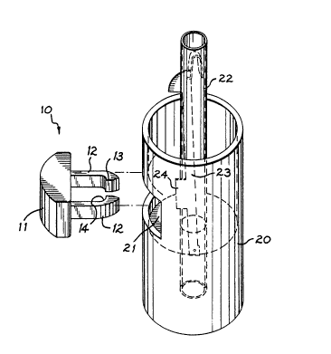
The push button 10 of this invention, as
shown in Figs. 1-10, is assembled with a handle 20 to
control a spring biased latch arm. The push button
can be of various shapes, e.g., square, circular or
triangular shape. The merits of this invention,
however, will be explained by referring to embodiments
which adopt a square push button. Further, the push
button structure of this application can be used with
automatic or self-opening umbrellas having various
types of cover rib linkage systems.
In the first push button 10 embodiment shown
in Figs. 1-3, a flexible latch section that includes a
pair of opposed flexible clamping lugs 12 extend from
the inner surface of the push button body 11, the lugs
being adapted to flex in a direction normal to the
handle's longitudinal axis. A push button hole 21 is
provided at one side of the umbrella handle 20 for the
insertion of the push button 10. Each clamping lug 12
is provided with a latch section which includes an
inclined entry portion 13 at its end on its inside
surface, a clamping portion 14 adjacent to the in-
clined entry portion 13 also on its inside surface.
Note the outside breadth of the clamping lugs 12 is
less than the width of the button hole 21 so the lugs
can extend thereinto from outside the handle 20
without interference. Note also the gap between the
clamping lugs 12 is of a width about equal to the
diameter of centerpost 22 so the clamping lugs can be
clamped thereon when assembled therewith. In
assembly, the centerpost 22 is first installed in the
handle 20 with a spring biased latch arm 23 being
provided therein as shown in Figure 1. The latch arm
23 includes a projection 24 oriented to face the push
button hole 21. Hence, when the push button's latch
section with clamping lugs 12 is pushed into and
through the push button hole 21, the clamping lugs
inclined entry portions 13 allow the lugs 12 to flex
over and around the centerpost 22 until the button's
inner body surface is seated against the latch arm's
projection 24, compare Fig. 2 to Fig. 3. In this
final assembly position, the clamping lugs 12 grip the
centerpost 22 therebetween with same being held
clamped thereto by the clamping lugs' clamping
portions 14. In use, and as can be seen from Fig. 3,
the latch arm 23 can be pivoted from a latch or
umbrella storage position (shown in Fig. 3) to an
unlatch or umbrella extend position (not shown) simply
by pushing the push button into the handle 20 until
the button's inner body surface abuts the centerpost
22. This travel motion is permitted because of the
length of the clamping lugs 12, i.e., because of the
length of the lugs' arms between the push button's
inner body surface and the lugs' latch sections 14.
In the second push button 10 embodiment
shown in Figs. 4-7, the flexible latch section in-
cludes a pair of opposed flexible clamping lugs 12
that extend from and comprise part of the side walls
of the push button body 11, the lugs being adapted to
flex in a direction normal to the handle's longi-
tudinal axis. A push button hole is provided at one
side of the umbrella handle for the insertion of the
push button 10. Each clamping lug 12 is provided with
a latch section that includes an inclined entry
portion 13 at its outside surface, and a clamping
portion 14 adjacent to the inclined entry portion 13
also on its outer surface. Note the outside breadth
of the clamping lugs 12 is substantially equal to the
width of the push button hole so the clamping lugs can
extend thereinto without interference from outside the
handle 20 except for certain latch structure on the
exterior surface of those lugs 12. Note also the push
button includes a central finger that extends from the
button's inside body surface that is adapted to
contact the latch arm's projection 24 as described
below. In assembly, the centerpost 22 is first
installed in the handle 20 with the spring-biased
latch arm 23 being provided therein as shown in Fig.
4. The latch arm 23 includes the pro~ection 24
oriented to face the push button hole 21. Hence, when
the latch section with clamping lugs 12 is pushed into
and through the push button hole 21, the clamping
lugs' incline entry portions 13 allow the lugs 12 to
flex inwardly through the hole until the latch
sections 13, 14 clear that hole and the push button's
inner finger is seated against the latch arm's projec-
tion 24, compare the installation sequence illustrated
in Figs. 5 to 6 to 7. In this final assembly
position, the clamping lugs 12, as shown in Fig. 7,
are seated against the inside surface of the handle
with the push button in the ready position, and with
the push button being held in clamped relation with
the handle by the clamping lugs' clamping portions 14.
In use, and as can be seen in Fig. 7, the latch arm
can be pivoted from a latch or umbrella storage
position ~shown in Fig. 7) to an unlatched or umbrella
extend position (not shown) simply by pushing the push
button 10 into the handle until the button finger's
--10--
inner surface 15 abuts the centerpost 22. This travel
motion is permitted because of the length of the
clamping lugs 12, i.e., because of the length of the
lugs' arms between the lugs' latch section 14 and the
push button's outer body surface.
In the third push button embodiment shown in
Figs. 8-10, the push button structure is generally
similar to the second embodiment shown in Figs. 4-7
except the push button structure has been re-oriented
or turned 90. More specifically, in the third
embodiment the push button's flexible latch section
includes a pair of opposed flexible clamping lugs 12
that extend from the top and bottom surfaces of the
push button body 11, the lugs being adapted to flex in
a direction parallel to the handle's longitudinal
axis. A push button hole is provided in one side of
the umbrella handle 20 for insertion of the push
button. Note the outside breadth of the clamping lugs
12 is essentially the same but slightly less than the
height of the button hole 21 so the lugs can extend
thereinto without significant interference from
outside the handle except for the lips' latch
sections. Each clamping lug 12 is provided with a
latch section that includes an inclined entry portion
13 at its end on its outside surface, and a clamping
portion 14 adjacent to the inclined entry portion 13
also on its outside surface. Note as in the second
-
embodiment, a finger extends from the push button's
inner surface, and that finger surface 15 is adapted
to cooperate with the latch arm's projection 24 as
explained in detail below. In assembly, and as with
the other embodiments, the centerpost 22 is first
installed in the handle 20 with the spring biased
latch arm 23 being provided therein as shown in Fig.
8. The latch arm 23 includes the projection 24
oriented to face the push button hole 21. Hence, when
the latch section with clamping lugs 12 is pushed into
and through the push button hole, the clamping lugs'
inclined entry portions 13 allow the lugs 12 to flex
inwardly relative to the hole's outer edges until the
button's fingers inner end 15 is seated against the
latch arm's projection 24, compare Fig. 9 to 10. In
this final assembly position, the clamping lugs 12 are
flexed outwardly, as shown in Fig. 10, so the push
button cannot be pulled out of the handle. In use,
and as can be seen also from Fig. 10, the latch arm 23
can be pivoted from a latch or umbrella storage
position (shown in that Fig. 10) to an unlatch or
umbrella extend position (not shown) simply by pushing
the push button 10 into the handle 20 until the button
finger's inner surface 15 abuts the centerpost 22.
This travel motion is permitted because of the length
of the clamping lugs 12, i.e., because of the length
of the lu~s' arms between the lugs latch sections 14
and the push button's outer surface.
Having described my invention in detail,
what I desire to claim and protect by Letters Patent
is: