Note: Descriptions are shown in the official language in which they were submitted.
2042263
-- 1 --
RD-20,202
_13~ L~ L 3~ TLL~E GARN~
This application is related to application Serial
No.(RD-19,452), entitled "~igh Speed, Radiation
Tolerant, CT Scintillator System Employing Garnet Structure
Scintillators" by C.D. Greskovich et al. and application
Serial No. (RD-20,194), entitled "Hole-Trap-
Compensated Scintillator Material", by V.G. Tsoukala et al.,
each of which is being filed concurrently herewith and is
incorporated herein by reference in its entirety.
Ba~kground of the Tnvent ~ ~n
Fiel~LQf ~he InventlQn
10 The present invention relates to the field of
ceramic materials, and more particularly, to the field of
transparent ceramic materials. It also relates to the field
of x-ray sensitive, solid luminescent scintillators suitable
for use in high speed computed tomography (CT) scanning
systems, particularly medical CT systems.
Background Information
A luminescent material absorbs energy in one
portion of the electromagnetic spectrum and emits energy in
another portion of the electromagnetic spectrum. A
luminescent material in powder form is commonly called a
phosphor, while a luminescent material in the form of a
transparent solid body is commonly called a ssi~ LLL~QL
Most useful phosphors emit radiation in the visible
portion of the spectrum in response to the absorption of the
radiation which is outside the visible portion of the
spectrum. Thus, the phosphor performs the function of
converting electromagnetic radiation to which the human eye
is not sensitive into electromagnetic radiation to which the
20~2263
-- 2
RD-20,202
human eye is sensitive. Most phosphors are responsive to
more energetic portions of the electromagnetic spectrum than
the visible portion of the spectrum. Thus, there are powder
phosphors which are responsive to ultraviolet light (as in
fluorescent lamps), electrons (as in cathode ray tubes) and
x-rays (as in radiography).
Two broad classes of luminescent materials are
recognized. These are self-activated luminescent materials
and impurity-activated luminescent materials.
A self-activated luminescent material is one in
which the pure crystalline host material upon absorption of a
high energy photon elevates electrons to an excited state
from which they return to a lower energy state by emitting a
photon. Self-activated luminescent materials normally have a
broad spectrum emission pattern because of the relatively
wide range of energies which the electron may have in either
the excited or the lower energy states with the result that
any given excited electron may emit a fairly wide range of
energy during its transition from its excited to its lower
energy state, depending on the particular energies it has
before and after its emissive transition.
An impurity activated luminescent material is
normally one in which a non-luminescent host material has
been modified by inclusion of an activator species which is
present in the host material in a relatively low
concentration such as in the range from about 200 parts per
million (ppm) to about 1,000 ppm. However, some phosphors
require several mole percent of activator ions for optimized
light output. With an impurity activated luminescent
material, the host crystal absorbs the incident photon and
the absorbed energy may be accommodated by the activator ions
or it may be transferred by the lattice to the activator
ions. One or more electrons of the activator ions are raised
to a more excited state. These electrons, in returning to
~2263
-- 3
RD-20,202
their less excited state, emit a photon of luminescent light.
In many commonly employed impurity activated luminescent
materials, the electrons which emit the luminescent light are
d or f shell electrons whose energy levels may be
significantly affected or relatively unaffected,
respectively, by the surrounding crystal field. In those
situations where the activator ion is not much affected by
the local crystal field, the emitted luminescent light is
substantially characteristic of the activator ions rather
than the host material and the luminescent spectrum comprises
one or more relatively narrow emission peaks. This contrasts
with a self-activated luminescent material's much broader
emission spectrum. In those situations where the electron
energies of the activator ions are significantly affected by
lS the crystal structure, the luminescent spectrum is normally a
fairly broad one similar to that of a self-activated
luminescent material. The host materlal of an impurity
activated luminescent material normally has many other uses
in which no activating species is present. In some of those
uses, that host material may include other species to modify
its properties, and may even include constituents which are
luminescent activators, but which are included in the
composition because of non-luminescent characteristics which
they impart to that composition.
There are a vast number of known phosphors each of
which has its own set of properties such as the turn-on
delay, efficiency, primary decay time, afterglow, hysteresis,
luminescent spectrum, radiation damage and so forth. The
turn-on delay of a luminescent material is the time period
be~ween the initial impingement of stimulating radiation on
the luminescent rnaterial and the luminescent output reaching
its maximum value, for a constant intensity of stimulating
radiation. The efficiency of a luminescent material is the
percentage of the energy of the absorbed stimulating
_ 4 _ 20~2263
RD-20,202
radiation which is emitted as luminescent light. When the
stimulating radiation is terminated, the luminescent output
from a scintillator decreases in two stages. The first of
these stages is a rapid decay from the full luminescent
output to a low, but normally non-æero, value at which the
slope of the decay changes to a substantially slower decay
rate. This low intensity, normally long decay time
luminescence, is known as afterglow and usually occurs with
intensity values less than 2% of the full intensity value.
The initial, rapid decay is known as the primary decay or
primary speed and is measured from the time at which the
stimulating radiation ceases to the time at which the
luminescent output falls to 1/e of its full intensity value.
A luminescent material exhibits hysteresis if the
amount of luminescent light output for a given amount of
incident stimulating radiation depends upon the amount of
stimulating radiation which has been recently absorbed by the
luminescent material. The luminescent spectrum of a
luminescent material is the spectral characteristics of the
luminescent light which is emitted by that material.
Radiation damage is the characteristic of a
luminescent material in which the quantity of light emitted
by the luminescent material in response to a given intensity
of stimulating radiation changes after the material has been
exposed to a high radiation dose. Radiation damage may be
measured by first stimulating a luminescent material with a
known, standard or reference, intensity of radiation~ The
initial output ~Io) of the photodetector in response to this
reference intensity of incident stimulating radiation is
measured and recorded or stored. Next, the luminescent
material is exposed to a high dosage of radiation. Finally,
the luminescent material is immediately again exposed to the
reference intensity of stimulating radiation and the final
output (If) of its photodetector, in response to this
2~2263
-- 5
RD-20,202
reference intensity of stimulating radiation, is measured and
stored or recorded. The radiation damage (~D) may then be
expressed as:
RD =If~I
Io (1)
Ideally, the radiation damage should be as small as possible.
In most luminescent materials, it is a negative number
because If is normally le5s than Io. However, if the
afterglow magnitude is 2 0.1% at ~ 100 milliseconds after
cessation of x-radiation, then unreliable and positive
numbers for radiation damage may be obtained.
In phosphors for use in radiography, many of these
characteristics can vary over a wide range without adversely
affecting overall system performance. In other applications,
each of these characteristics must be strictly specified to
obtain maximum or practical performance.
In a computed tomography (CT) scanning system, an
x-ray source and an x-ray detector array are positioned on
opposite sides of the subject and rotated around the subject
in fixed relation to each other. Early CT scanning systems
employed xenon gas as their x-ray detection medium. In these
systems, incident x-rays ionize the xenon gas and the
resulting ions are attracted to charged plates at the edge of
the cell and the scintillator output is a charge or current.
More recently, CT scanners with solid scintillators have been
introduced. In a solid scintillator system, the scintillator
material of a cell or element absorbs x-rays incident on that
cell and emits light which is collected by a photodetector
for that cell. During data collection, each cell or element
of the detector array provides an output signal
representative of the present light intensity in that cell of
the array. These output signals are processed to create an
- 6 - 2~12263
RD-20,202
image of the subject in a manner which is well known in the
CT scanner art. It is desirable for the luminescent material
in a CT scanner to have a linear characteristic in which the
light output is a linear function of the amount of
stimulating radiation which is absorbed in order that light
output may be directly converted to a correspondi~g intensity
of stimulating radiation in a linear manner.
In systems such as CT scanners, the luminescent
material must have many specialized characteristics which are
not needed in many of the previously mentioned phosphor based
systems. First, in x-ray based CT systems, it is desirable
to absorb substantially all of the incident x-rays in the
luminescent material in order to minimize the x-ray dose to
which the patient must be exposed in order to obtain the
computed tomography image. In order to collect substantially
all of the incident x-rays, the luminescent material must
have a thickness in the direction of x-ray travel which is
sufficient to stop substantially all of the x-rays. This
thicknees depends both on the energy of the x-rays and on the
x-ray stopping power of the luminescent material. Second, it
is important that substantially all of the luminescent light
be collected by the photosensitive detector in order to
maximi~e overall system efficiency, the signal to noise ratio
and the accuracy with which the quantity of incident
stimulating radiation may be measured. In order to extract
substantially all of the luminescent light generated in the
luminescent material of the CT scanner, the luminescent
material should be transparent to the luminescent light.
Otherwise much of the luminescent light will not reach the
photosensitive detector because of scattering and absorption
within the luminescent material. Consequently, the
luminescent material is provided in the form of a solid bar
which is substantially transparent to the luminescent light
and which is thick enough in the direction of x-ray travel to
- 7 - 2~422~3
RD-20,202
absorb substantially all of the incident x-rays. This
complicates both the selection of a luminescent material for
use in CT scanning and its preparation since many materials
which are known to luminesce and which have been used or
tested as powder phosphors cannot be provided in the form of
a solid bar having the necessary transparency.
The luminescent properties of materials have nQL
been tabulated in handbooks in the manner in which the
melting point, boiling point, density and other more mundane
physical characteristics of various compounds have been
tabulated. Most luminescent data is found in articles with
respect to particular materials which the authors have
measured for one reason or another. Further, most
characterization of luminescent materials has been done using
lS ultraviolet (UV) light as the stimulating radiation because
ultraviolet light is more easily produced than x-rays and is
generally considered less harmful. Unfortunately, there are
a number of materials which are luminescent in response to
ultraviolet light stimulation which are not luminescent in
response to x-ray stimulation. Consequently, for many
materials, even that luminescent data which is available
provides no assurance that the material will luminesce in
response to x-ray stimulation. Further, for many
applications of phosphors many of the parameters which must
be closely controlled in a scintillator for use in a state-
of-the-art CT scanning system are unimportant and thus have
not been measured or reported. Consequently, existing
luminescent material data provides little, if any, guidance
in the search for a scintillator material appropriate for use
in a state-of-the-art CT scanning system. Among the
parameters on which data is generally unavailable are
radiation damage in response to x-ray stimulation, afterglow,
susceptibility to production in single crystalline form,
hysteresis phenomena, mechanical quality and in many cases,
2~1422~
-- 8
RD-20,202
even whether they are x-ray luminescent. The large number of
parameters which must meet strict specifications in order for
a given material to be suitable for use in a state-of-the-art
CT scanner, including the ability to provide the material in
the form of transparent scintillator bodies, makes the
process of identifying a suitable scintillator material one
which essentially begins from scratch and is akin to
searching for "a needle in a haystack". The difficulty of
identifying such a material is exemplified by the use of
cadmium tungstate and cesium iodide activated with thallium
in CT scanning machines presently being marketed despite the
fact that each of these materials has a number of
characteristics (discussed below) which are considered
undesirable for a state-of-the-art CT scanner scintillator.
There are several reasons that it is desirable that
the radiation damage be as small as possible. One
disadvantage of high radiation damage is that as radiation
damage accumulates, the sensitivity of the system decreases
because of the progressively smaller quantity of light which
is emitted by the scintillator material for a given
stimulating dosage of radiation. Another disadvantage is
that for too high a radiation damage, the scintillation
detectors must eventually be replaced because of the
cumulative effects of the radiation damage. This results in
a substantial capital cost for the replacement of the
scintillation detecting system. A more bothersome, and
potentially even more expensive effect of high radiation
damage is a need to recalibrate the system frequently during
the working day, and potentially as frequently as after every
patient. Such recalibration takes time and also exposes the
scintillator material to additional radiation which
contributes further damage. It is considered desirable that
the radiation damage of a scintillator material for use in a
CT scanning system be small enough that calibration of the
210~22~3
g
RD 20,202
system at the beginning of each working day is sufficient to
ensure accurate results throughout the working day.
One way of providing the luminescent material in
the form of a transparent bar is to employ a single
crystalline luminescent material which is transparent to its
own luminescent radiation. A common method of growing single
crystals is the Czochralski growth technique in which
appropriate source materials are placed in a high temperature
crucible which is often made of iridium (Ir) and the crucible
and its contents are heated to above the melting point of the
desired single crystalline material. The resulting molten
material is known as the melt. During growth, the melt
temperature is held at a value at which the upper portion of
the melt is cool enough for single crystalline material to
grow on a seed crystal brought into contact with the melt,
but not to spontaneously nucleate. A seed crystal of the
- desired material or one on which the desired material will
grow as a single crystal is lowered into contact with the top
of the melt. As the desired crystalline material grows on
the seed crystal, the seed crystal is withdrawn (pulled
upward) at a rate which maintains the growing boule of single
crystalline material at a desired diameter. Typically, the
seed crystal is rotated during growth to enhance the
uniformity of the growing crystal. The source material which
is initially placed in the crucible may take any appropriate
form, but is normally a mixture of appropriate quantities of
source materials which together provide a melt having the
stoichiometry and impurity control desired for the single
crystalline material to be grown.
When a pure crystal is grown from a corresponding
melt, the Czochralski growth technique normally provides a
high quality, uniform composition single crystal of the
desired composition. When it is desired to produce a crystal
having substitutions for some portion of the atoms of the
~8~2263
-- 10 --
RD-20,202
pure crystalline material, the growth dynamics are more
complex and the manner in which the substituent enters into
the crystal structure and thus its concentration in the melt
and boule as functions of time depend on a number of
characteristics. One of the effects of these characteristics
is characterized as the segregation coefficient. The
segregation coefficient has a value of 1 when the substituent
is normally present in the solid boule in the same ratio as
it is present in the source melt. The segregation
coefficient is greater than 1 when the substituent is
normally present in the solid boule in greater concentration
than it is present in the source melt and the segregation
coefficient is less than 1 when the substituent is normaily
present in the solid boule in lesser concentrations than it
is present in the melt. While there are a number of
different fundamental reasons for these differences, the
segregation coefficient is an effective means of expressing
the result.
Where slabs or bars of the single crystalline
material are desired, the Czochralski-grown single
crystalline boule is sliced into wafers and then into bars of
the desired configuration. The only two single crystalline
luminescent materials known to be in use in commercial CT
scanning systems are cesium iodide (CsI) and cadmium
tungstate (CdW04). The cesium iodide i5 thallium ~Tl)
activated while the cadmium tungstate is a pure, self-
activated luminescent material. CsI produces a luminescence
output having a peak emission at about 550 nm and exhibits
appreciable hysteresis and radiation damage. CdWO4 produces
a luminescence output having a peak at about 540 nm and
exhibits high radiation damage, although to a lesser extent
than CsI. The radiation damage with CsI is severe enough,
that recalibration of the system between pa~ients is often
desirable. While the radiation damage in CdWO4 is less than
2~2263
-- 11 --
RD-20,202
that, recalibration more than once a day is considered
desirable. As a consequence of these radiation damage
characteristics, systems which employ either of these
materials as their scintillating material suffer from a
decrease in sensitivity as radiation damage accumulates and
must eventually have their scintillator system replaced.
In a CT scanning system, one of the crucial
characteristics of a scintillator bar is its Z-axis response
curves. Individual scintillator bars are normally narrow for
maximum resolution and deeper than wide to provide adequate
x-ray stopping power and relatively long perpendicular to the
plane of the x-ray beam/scintillator system in order to
collect sufficient x-rays to be efficient. The Z-axis
characteristic is the photodetector output in response to a
constant intensity, narrow, x-ray stimulating beam as that
beam is scanned from one Z-direction end of the scintillator
bar to the other. Ideally, this characteristic is symmetric
about the longitudinal center of the scintillator bar and
increases monotonically from each end to the center. The
increase in output near the ends of the bar is preferably
complete once the entire Z-direction thickness of the beam is
disposed on the scintillator bar, with the output being
substantially uniform along the intervening portion of the
bar.
In order to mee~ these Z-axis requirements, the
scintillator bar must have substantially uniform optical,
luminescent and source radiation absorption properties along
its entire length. For single crystal, impurity-activated
scintillator bars, this requires the ability to grow source
boules having uniform luminescent activator concentration
both radially and lengthwise of the boule, since the
luminescent output is dependent on the local concentration of
the activator ion. Consequently, the process of selecting a
scintillator material for a CT scanner, in addition to
20~22~3
- 12 -
RD-20,202
determining all of the other important properties of the
material, must also include establishing the feasibility of
producing scintillator bars with acceptable Z-axis
characteristics.
In a CT scanner, it is preferable to provide a
reflective sur~ace on all surfaces of the scintillator bar
other than the surface along which the photodetector diode is
disposed. Thus, a typical solid scintillation detector
system comprises a plurality of individual scintillator bars
positioned side-by-side with an individual photodetector
diode coupled to each scintillator bar to convert its
luminescent light into a corresponding electrical signal. It
is important in such a system that all of the scintilla'or
bars have similar overall conversion efficiencies (that is,
substantially identical electrical output signals for
identical incident x-ray radiation). This places another
limitation on the selection of the scintillator material in
that it must be possible to produce a sufficient quantity of
scintillator bars having similar characteristics to assemble
a scintillation detector having as many as 1,000 or more
elements.
The primary decay time determines how fast a CT
scanner can scan a patient since it is necessary for the
luminescent output in response to radiation incident in one
position of the scanner to have ceased before the luminescent
output at another position of the scanner can be accurately
measured. At present, a primary decay time of less than 500
microseconds is preferred, with still lower values being more
desirable if they can be obtained without undesirable affects
on other properties of the scintillator material such as
maximum light output, radiation damage and hysteresis. It is
also desirable that the maximum afterglow level be very small
and that it decay relatively rapidly. For modern CT
scanners, afterglow may be measured at 100 to 150
2~42~3
- 13
RD-20,202
milliseconds after stimulating radiation termination and
again at 300 milliseconds to characterize a scintlllator
material. An afterglow of less than 0.1% is considered
highly desirable since the photodetector cannot distinguish
between luminescent light which is a result of afterglow from
earlier stimulation and luminescent light which is a result
of present stimulation. Thus, afterglow can limit the
intensity resolution of a CT scanner system.
For purposes of comparing the efficiency of
different candidate scintillator materials, it is convenient
to normalize light output. The amplitude of the output
signal from a photodetector diode in response to stimulation
of a standard sized scintillator bar of the candidate
material with an established reference intensity of x-rays is
compared with the output produced by cadmium tungstate of the
same configuration in response to the same stimulation.
Cadmium tungstate is a convenient standard because the self-
activated nature of its luminescence results in substantially
fixed light output for a given intensity of stimulating
radiation so long as it has not been heavily radiation
damaged, since its light output does not depend on the
concentration of an activator. Thus, light output data taken
by different individuals and at different times can be
directly compared without having to first establish the
calibration of different test setups.
It is desirable to have computed tomography
scanning systems operate as fast as possible to maximize the
number of patients which can be examined by a computed
tomography scanner each working day and because the shorter
time a scan takes, the easier it is for a patient to hold
still during the scan. Further, the movement of internal
organs is minimized.
As the scannlng speed of a CT system is increased,
the signal amplitude decreases for a fixed x-ray dose rate.
14 - 20~2263
RD-20,202
Consequently, the signal-to-noise ratio, the contrast and
thus the useful intensity resolution will decrease uniess
system parameters are adjusted to reduce noise. In order to
reduce noise, the primary decay time of the scintillator
should be reduced to a value where it does not contribute
noise to the system. The afterglow should also be reduced as
much as possible, since it provides a background luminescence
intensity which is a noise contribution to the photodetector
output. Selecting a scintillator material having its peak
output in the vicinity of the peak sensitivlty of the
photodetector has the effect of reducing noise by increasin~
signal amplitude. Other modifications can also assist in
maintaining the signal-to-noise ratio.
As the CT scanner field has matured, the speed of
the electronics has increased, thus making faster
scintillators desirable in order that a data scan may be
performed in less time. It i5 now desired to operate CT
scanning systems at speeds which require scintillators which
are much faster than what was required as little as five
years ago. Consequently, there is a vast lack of data about
known solid luminescent materials which would be needed in
order to select and make a scintillator material which is
appropriate for use in a state-of-the-art CT scanning system
where high speed electronics must be matched by a still
higher speed scintillation material.
Separate from the problem of determining all these
characteristics for individual candidate materials, is the
problem that in a scintillation scanner, material must be
provided in the form of a transparent solid body. Many
luminescent materials which can be provided in powder form
cannot be provided in a single crystalline form and thus are
not available as transparent bodies. This inability to
produce particular luminescent materials as single
crystalline material can be a result of incompatibility of
2~22~
- 15 -
RD-20,202
crystal structures, instability at Czochralski growth
temperatures, low solubility of some components of a
luminescent material in the crystal structure or the melt, a
segregation coefficient which results in a non-uniform
distribution within the boule of the additives and/or
substituents or other reasons. Consequently, even if a
particular luminescent composition is identified as
apparently having desirable properties for use in a
scintillation detector of a computed tomography machine,
production of such a scintillator detector is not
straightforward. In many cases, the desired composition
cannot be produced as a single crystalline material.
Scintillation counters are used to count high
energy particles, in physics research. These scintillation
counters normally comprise a solid transparent body (often a
plastic with a luminescent material dispersed in it) whlch is
coupled to a photomultiplier tube to detect the very faint
luminescence produced by absorption of a single particle.
The materials used for such scintillation counters must have
a very short primary decay time ~preferably much less than
100 nanoseconds) in order to distinguish separate, but
closely spaced-in-time events from each other in order that
the desired counting may take place. The other
characteristics which are important to the use of a material
as the scintillator in a CT scanning system are of little
consequence in the scintillation counter art so long as the
afterglow is low enough that a new primary scintillation can
be distinguished from any background afterglow resulting from
previous events. These scintillation counters can use
luminescent materials whose afterglow would present a problem
in the CT scanning art. Consequently, although work has been
done on scintillation materials for use in scintillation
counting applications, such work is only peripherally
- 16 - 2042263
RD-20,202
relevant to a search for a scintillation material for use in
a CT scanning system.
There are a number of luminescent materials which
can be produced by flux growth techniques as small single
crystals, but which cannot be produced as large single
crystals because they are unstable at high temperatures and
decompose into constituent materials. Other luminescent
materials have been produced as thin films in attempts to
develop phosphors for projection cathode ray tubes in order
to minimize light loss due to scattering in amorphous or
polycrystalline films. Such materials have no utility for
the scintillators of CT scanners in the absence of an ability
to provide a transparent body having sufficlent thickness
(generally at least 1 mm thick) for the material to be
effective at stopping the x-rays employed in a CT scanning
system. Further, the reports of the development work done on
these materials contain no data on many characteristics which
are crucial to determining whether a material is suitable for
use in a CT scanning system.
A polycrystalline alternative to the single
crystalline scintillator materials cesium iodide and cadmium
tungstate is disclosed in U.S. Patents 4,421,671; 4,466,929;
4,466,g30; 4,473,413; 4,518,545; 4,518,546; 4,525,628;
4,571,312; 4,747,973 and 4,783,596. The scintillator
composition disclosed in these patents is a cubic yttrium
gadolinium oxide doped with various rare earth elements to
provide a scintillator material having desired luminescent
properties. These materials have not been prepared in single
crystalline form because of the difficulty of growing
crystals with desired, uniform distribution of all of the
necessary constituents. As is further disclosed in the above
recited patents, a method was developed for providing this
doped yttrium-gadolinium oxide scintillator material in a
polycrystalline ceramic form in which it is sufficiently
- 17 - 2~22~3
RD-20,202
transparent to provide an excellent scintillator material.
This material has the substantial advantage over the cesium
iodide and cadmium tungstate of being essentially free of
radiation damage and hysteresls as well as having a
sufficiently low afterglow to satisfy ~he requirements for a
high quality CT scanning system. ~nfortunately, this
material has a primary decay time OA the order of l,000
microseconds and thus is not as fast as is desired for
present state-of-the-art CT scanning systems.
German patent DE 37 04 813 A1 describes a single
crystal Gd3_xCexAl5_yscyol2 scintillator prepared either by
first spray drying a source sulphate solution and calcining
the dried sulphate or mixing oxides -- each followed by
pressinq, sintering, melting and pulling a single crystal in
a high vacuum. A spectrum for the luminescent output from
this material is also presented with its peak in the vicinity
of 560nm.
It would be desirable to have a scintillator which
is fast, has a low afterglow, no hysteresis, no non-linearity
in output, high x-ray stopping power, high light output for a
given stimulating x-ray input and which emits light at a
frequency where photodetector diodes are particularly
sensitive.
Single crystalline yttrium aluminum garnet (YAG)
doped with neodymium is a known laser material. This
material has also been further doped with chromium to
increase the absorbence of the light frequency used to
optically pump a YAG laser. While attempts have been made to
produce transparent polycrystalline YAG, such attempts have
not been success~ul. Reduced opacity or increased
translucency or transparency has been reported in sintered
YAG where magnesium oxide or silicon dioxide was included in
the composition in a concentration of 500-2,000 ppm.
However, even with this addition, true transparency is not
- 18 ~ 2263
RD-20,202
obtained. Further, the inclusion of such transparency
promoters in a scintillator material would be expected to be
undesirable because of the potential for these impurities to
adversely effect one or more of the desirable properties of a
scintillator material.
Many garnets are transparent in the infrared
region. Consequently, transparent ceramic garnets would be
desirable for use as combined visible/infrared windows where
true transparency was obtained throughout this portion of the
spectrum.
~hjects of the. I&~n~ion
Accordingly, a primary object of the present
invention is to provide a CT scintillator detection system
with a polycrystalline, transparent scintillator which has a
short primary decay time, has a low afterglow and has
acceptable hysteresis, radiation damage and non-linearity in
response to x-ray stimulation.
Another object of the present invention is to
provide a CT scintillator detector with improved
polycrystalline scintillator material.
Still another object of the present invention is to
provide a long life polycrystalline CT scintillator detector
system which can operate at higher scanning speeds than
existing systems without radiation damage and other
undesirable characteristics.
A further object of the present invention is to
provide a polycrystalline CT scintillation detector having
the desirable properties of high speed, high output, high x-
ray stopping power combined with low values of the
undesirable properties of afterglow, hysteresis, non-
linearity and radiation damage susceptibility.
A still further object of the present invention is
to provide transparent polycrystalline garnet ceramics having
- 13 - 2042263
RD-20,202
a controllable composition including partial substitution for
cations of a basic garnet composition.
A still further object of the present invention is
to provide such structures in which the basic garnet is a
gadolinium garnet.
An additional object of the present invention is to
provide transparent polycrystalline garnets suitable for use
as the active medium of lasers.
Summary of ~he Inventio~
Accordingly, the above and other objects which will
become apparent from the specification as a whole, including
the drawings, are accomplished by provision of cubic,
polycrystalline, ceramic garnet materials having a density of
at least 99.9% of theoretical density. These materials
comprise a host garnet activated for x-ray or
photoluminescence with appropriate ions which may include
chromium, cerium, neodymium and other cations including
mixtures of cations. In particular, those polycrystalline
garnet compositions having more than one activator cation
present at low concentrations are particularly desirable
since such compositions are exceedingly difficult or
impossible to produce in single crystalline form because of
an inability to grow crystals having a uniform distribution
of the various substituents throughout a single crystalline
boule.
The host garnets for these materials may be three
element (two cation) garnets such as gadolinium gallium
garnet (Gd3Ga5O12) or yttrium aluminum garnet ~Y3AlsO12), for
example, or may comprise more that three elements such as
gadolinium scandium gallium garnet (Gd3Sc2Ga3O12) or
gadolinium scandium aluminum garnet (Gd3Sc2Al3ol2) for
example.
- 20 - 2~22~3
~D-20, 202
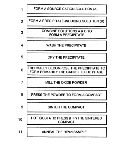
Such transparent polycrystalline garnet materials
may be produced by a number of different methods. These
include forming a chloride solution of the desired cations in
appropriate relative concentrations, inducing formation of a
substantially uniform composition precipitate by mixing this
chloride solution with another appropriate solution such as
ammonium oxalate or ammonium hydroxide. The precipitate is
separated from the solution by filtering, centrifuging or
other appropriate processes, dried and then heated to a
thermal decomposition temperature typically in the range from
600 C to l,OOO C to produce a powder having the desired
garnet composition. The resulting powder is then preferably
milled and screened to eliminate particle agglomeration and
to ensure that the majority of the particles used in the
subsequent process are less than 10 microns in diameter.
This dried, fine powder is then pressed to form a
compact in the desired configuration. Thereafter, the
compact is sintered to about >99.9% of theoretical density,
or alternatively, sintered to a closed pore stage and then
20 hot isostatic pressed to still higher density. ~pon
polishing, the resulting ceramic body is transparent.
In particular, gadolinium gallium garnet
(Gd3GasO12), gadolinium scandium gallium garnet ~Gd3Sc2Ga3Ol2)~
gadolinium scandium aluminum garnet (Gd3Sc2Al~O12), each
25 activated with chromium 3+ ions in a concentrations from
about 0.07 to 1. 2 wt% Cr2O3, yttrium aluminum garnet
(Y3A15O12) activated with cerium 3+ ions at a concentration of
about 0.33 wt% Ce2O3 or neodymium 3+ ions at a concentration
of about 0.85 wt% Nd2O3 are particular examples of
scintillator compositions which can provide the benefits of
high speed, high output, low afterglow, high x-ray stopping
power, emission of light in the sensitive portion of a
photodetector diode's characteristics and acceptable
hysteresis, non-linearity and minimal radiation damage.
- 21 - 2~ ~ 226 3
RD-20,202
Other garnet host compositions and other activators may also
be employed. For simplicity, we shall denote Gd3Ga5O12 as
GGG, Gd3Sc2Ga3O1~ as GSGG, Gd3Sc2Al3Ol2 as GSAG and Y3Al5O12 as
YAG.
Bri~ 5~ ~ L~e D~aw~nas
The subject matter which is regarded as the
invention is particularly pointed out and distinctly claimed
in the concluding portion of the speclfication. The
invention, however, both as to organization and method of
practice, together with further objects and advantages
thereof, may best be understood by reference to the following
description taken in connection with the accompanying
drawings in which:
Figure 1 is a schematic illustration of a CT
scanning system;
Figure 2 illustrates a sequence of processing steps
for forming a transparent, polycrystalline garnet body in
accordance with the present invention;
Figure 3 presents spectral transmission curves;
Figure 4 illustrates the infrared transmission
curves for the disk used in Figure 3;
Figures 5A and 5B are photomicrographs of a ceramic
garnet in accordance with this invention; and
Figure 6 compares diffuse transmittance of single
crystalline and ceramic materials.
A computed tomography (CT) scanning system 100 is
illustrated schematically in Figure 1. This CT scanning
system 100 comprises a cylindrical enclosure 110 in which the
patient or object to be scanned is positioned. A gantry 112
surrounds the cylinder 110 and is configured for rotation
about the cylinder's axis. The gantry 112 may be designed to
- 22 - 2~2263
RD-20,202
revolve for one full revolution and then return or may be
designed for continuous rotation, depending on the system
used to connect the electronics on the gantry to the rest of
the system. The electronics on the gantry include an x-ray
source 114 which preferably produces a fan x-ray beam which
encompasses a scintillation detector system 116 mounted on
the gantry on the opposite side of the cylinder 110. The fan
pattern of the x-ray source is disposed in the plane defined
by the x-ray source and the scintillation detector system
116. The scintillation detector system 116 is very narrow or
thin in the direction perpendicular to the plane of the x-ray
fan beam. Each cell 118 of the scintillation detector system
incorporates a solid transparent bar of scintillator material
and a photodetector diode optically coupled to that
scintillator bar. The output from each photodetector diode
is connected to an operational amplifier which is mounted on
the gantry. The output from each operational amplifier is
connected either by individual wires 120 or by other
electronics to the main control system 150 for the computed
tomography system. In the illustrated embodiment, power for
the x-ray source and signals from the scintillation detector
are carried to the main control system 150 by a cable 130.
The use of the cable 130 generally limits the gantry to a
single full revolution before returning to its original
position. Alternatively, slip rings or optical or radio
transmission may be used to connect the gantry electronics to
the main control system 150 where continuous rotation of the
gantry is desired. In CT scanning systems of this type, the
scintillator material is used to convert incident x-rays to
luminescent light which is detected by the photodetector
diode and thereby converted to an electrical signal as a
means of converting the incident x-rays to electrical signals
which may be processed for image extraction and other
purposes. At present, one of the limitations on the
- 23 - 2~22~3
RD-20,202
capabilities of such systems is the characteristics of the
scintillator compositions, whether they be xenon gas or bars
of solid scintillator material.
We have identified a class of luminescent materials
which are appropriate for use as scintillators in high speed
x-ray CT scanning systems of the type illustrated in Figure
1. In particular, they luminesce in response to x-ray
stimulation, have primary decay times of less than 500
microseconds, have afterglow levels of less than 0.2% at 100
to 300 milliseconds after the cessation of x-ray stimulating
radiation, exhibit radiation damage having a magnitude of
less than 5% after an exposure to between 500 and 1,000 rads
of x-rays, exhibit essentially no hysteresis and when grown
as single crystals by the Czochrals~i technique, are
reasonably transparent to their luminescent light and
typically have light outputs which range from about 100% to
about 350% of that produced by cadmium tungstate single
crystal, a material used in commercial x-ray body scanners.
This class of scintillator material is based on
activated luminescence of cubic garnet crystals. Garnets are
a class of materials with the crystal chemical formula A3BsO12
in which the A cations are eight-coordinated with oxygens and
the B cations are either octahedrally (six) or tetrahedrally
(four) coordinated with oxygens. The crystal structure is
cubic with 160 ions per unit cell containinq eight formula
units. In accordance with the present invention, the A
cations are rare earth or yttrium ions alone, in combinations
and/or with activator substitutions. The B cations may be
rare earth ions or other ions, again, alone, in combinations
and/or with substitutions. In particular, we have found that
with activator ions substituted in the eight-coordinated or
six-coordinated sites, these garnets are luminescent in
response to x-ray stimulation. A particularly important
activator ion which we have discovered is x-ray luminescent
- 24 _ 2 0 4 2 2 6 3
RD-20,202
in this host material is the chromium 3+ ion located in six-
coordinated sites.
The luminescent properties of the Cr3+ in garnet
host materials are characteristic of the Cr3+ ion in lattice
sites where the crystal field is relatively weak - that is,
those host garnets which have a green cast to them when
chromium is added, as opposed to those which has a red cast
(in which the chromium ion is disposed in a relatively strong
crystal field).
Examples of single crystalline garnet materials of
this type are presented in the related application Serial No.
(RD-19,452) entitled "High Speed, Radiation
Tolerant, CT Scintillator System Employing Garnet Structure
Scintillators". As is detailed therein, the single
crystalline boules of most of those materials had an
activator concentration which varied along the length of the
boule, and in many cases, with position across a wafer sliced
from the boule. Problems were also encountered with the
single crystalline boules developing cracks running generally
lengthwise thereof. Thus, although the single crystalline
materials in those examples have characteristics which make
them suitable for use as the luminescent scintillator in CT
scanning machines, the fabrication of scintillation detector
systems from those materials can be difficult and can involve
the production of a lot of material which turns out to be
unusable.
A further problem with the use of slngle crystal
gadolinium gallium garnet (GGG) is the tendency of pure GGG
to grow in a spiral pattern. Such growth is undesirable for
many uses and particularly where uniform scintillator bars
are desired. A known technique for preventing such spiral
growth is to add to the melt several tens of parts per
million of calcium oxide tCaO), the calcium ion being in a 2
oxidation state tCa+2). ~owever, for scintillator use, this
- 25 ~ 2~22~3
RD-20,202
has the undesirable effect of adding an additional cation to
the GGG crystal (and in particular one which is not in a 3+
o~idation state~ which may have undesirable effects on one or
more of the scintillator properties which are crucial for
state-of-the~art CT scanner use of a solid scintillator.
In accordance with the present invention, the
compositional control and uniformity is substantially
increased and the quantity of unusable material is
substantially reduced by forming the transparent, activated
garnet scintillator bars of polycrystalline material. The
polycrystalline process allows accurate control of the
concentration of a number of substituents, as may be desired,
and allows formation of arbitrary body shapes, as may be
desired. We have developed several ways of producing such
scintillator bars.
In these processes, we start by forming a
hydrochloric acid solution of the desired cations in
appropriate quantities. By appropriate quantities, we mean
relative concentrations which result in the final transparent
body containing the desired relative proportions of cations.
Thus, in those situations where cations are present in the
same relative concentrations in the final transparent body as
they are in the hydrochloric acid solution of the source
cations, it is that relative concentration which is desired
in the hydrochloric acid solution. In those situations,
where the quantity of one or more cations decreases relative
to the quantity of other cations during the process of
converting the source hydrochloric acid solution into the
final transparent polycrystalline body, then appropriate
quantities in the hydrochloric acid starting solution are
those quantities which result in the final transparent garnet
body having the desired composition.
The source compounds are preferably 99.99% or
higher purity in order to minimize the unknowniuncontrolled
20~2263
- 26 -
RD-20,202
impurities present in the final composition which can effect
radiation damage, afterglow and luminescent efficiency.
One way of forming this source chloride solution is
by dissolvin~ the source cations in the form of oxides in hot
concentrated hydrochloric acid. For those situations where a
closely controlled final garnet composition is desired,
especially where the absence of impurities is considered
desirable, use of source compounds which are of 99.99% or
higher purity is preferred. Naturally, the source cations
may be provided as chlorides rather than oxides, lf desired.
Other source compounds may also be used. Once the source
materials have completely dissolved in the hot concentrated
hydrochloric acid, the resulting solution is cooled to room
temperature. The resulting solution should be clear and free
of precipitates or settling out of any of the source
material. In the event that precipitation or settling out of
source material occurs, the solution should be reheated, and
additional hydrochloric acid added to the solution so that
upon cooling to room temperature again, no precipitation or
settling out occurs. That is, enough hydrochloric acid
should be used to ensure that the source materials are not
present at or above their solubility limit at room
temperature.
Separately, an ammonium oxalate (NH4)2C2O4 solution
is formed by dissolving ammonium oxalate or individual
amounts of ammonia and oxalic acid. Enough ammonium oxalate
should be prepared to ensure complete reaction with the
cation-containing chloride solution. This ammonium oxalate
solution should have a pH between about 7.5 and about 9.5.
It is considered preferable that the pH of this ammonium
oxalate solution be between 8.0 and 8.5.
When making small batches, we dripped the chloride
cation source solution into this ammonium oxalate solution
while the ammonium oxalate solution was being stirred. A
- 27 _ 204~2~3
RD 20,202
white precipitate formed instantly upon contact between the
two solutions. The inclusion of a magnetic stirring rod in
the mixing container is a preferred method of mixing these
solutions where small quantities are being prepared. Once
all of the chloride source solution has been added to the
ammonium oxalate solution, the precipitate formation is
complete. Since our work was directed to preparing these
materials for evaluation, we dripped the chloride cation
source solution into the ammonium oxalate solution rather
than just pouring the two together in order to ensure that no
cnemical inhomogeneity or separation of phases occurred
during our preparation process. This dripping was
accomplished at a rapid drip rate which was near streamlike.
During the process of adding the chloride source
solution to the ammonium oxalate solution, the pH of the
oxalate solution is preferably monitored with a pH meter and
maintained at a pH between 8.0 and 8.5 by addition of
ammonium hydroxide to the solution as required.
During the precipitation step, the precipitate
forms in small enough particles that initially, a colloidal
suspension of the precipitate in the oxalate solution is
present. Following the completion of the precipitation step,
this colloidal suspension will slowly settle out to leave a
white precipitate at the bottom of the container and a clear
solution above it. This settling process can be accelerated
by filtering and/or centri.fuging the precipitate-containing
liquid.
If desired, the precipitate may be water and/or
alcohol washed before separating the precipitate from the
liquid. This is done by allowing the precipitate to settle,
pouring off or otherwise removing most of the liquid and
adding the wash water or alcohol, allowing the precipitate to
settle again, and again removing the clear liquid. Where
high purity and/or closely controlled composition of the
2~42263
- 28 -
RD-20,202
final transparent garne~ is desired, the wash water should be
high purity, deionized water and the alcohol should be of
standard reagent grade purity. This washing process removes
excess ammonium oxalate and reaction products such as
ammonium chloride from the precipitate. The precipitate is
then separated from the wash solution by filtering,
centrifuging or other appropriate techniques. This
precipitate is a multi-component precipitate having a
substantially uniform chemical composition. This wet
precipitate is at present believed to be a complex of
ammonium gadolinium-gallium oxalate ~when preparing GGG),
however, the detailed chemical compound composition or
structure of this precipitate does not need to be known for
the success of this process. This precipitate is preferably
dried, such as by oven drying at a temperature of
approximately llO C for a day or by vacuum drying.
X-ray diffraction analysis of thls dried
precipitate prepared from source materials CrCl3-6H2O, Gd2O3
and Ga2O3 contains a number of x-ray peaks corresponding to
NH4Gd(C2O4)2-H2O ~an ammonium gadolinium oxalate complex).
This dried precipitate is then heated in air to a temperature
of about 750 C to thermally decompose it.
We have found several different results of this
decomposition when preparing a gadollnium garnet doped with
small quantities of other cations such as Cr3+, Ce3+ or Nd3~.
In some cases, the resulting powder was substantially
gadolinium garnet which was accompanied by minor amounts of
the ~-Ga2O3 and C-Gd2O3 phases. Frequently, only the garnet
phase was observed. This was particularly true where the
decomposition was carried out at 900 C in air. When pure GGG
was formed, the resulting powder was white. Where small
amounts of Cr3+ ions were included in the composition, the
resulting powder was light green in color.
2042263
- 29 -
RD~20,202
The specific surface area of the GGG:Cr powders
formed at decomposition temperatures of 800 to 1,OOO C were
measured by the BET nitrogen absorption method and ranged
between about 5 and 15 m2g~l which correspond, respectively,
to a equivalent spherical diameters of 0.17 to 0.06 microns.
The particle size distributions measured by the x-ray
sedigraph method revealed that powder particles had sizes
ranging between about 0.15 and 20 microns, suggesting that
the as-thermally-decomposed garnet powders are appreciably
agglomerated. If these powders are die or isostatically
pressed at pressures up to 60,000 psi to form powder compacts
for sintering with relative densities of up to about 55% and
the compacts are sintered at temperatures of 1,500 to 1,650 C
in oxygen, the resulting ceramic body is typically opaque to
translucent with relatively high amounts of residual porosity
located within the garnet grains of the microstructure.
This powder may be directly pressed to produce a
compact for sintering. However, it is preferred to first
mill this powder either in a ball mill using zirconia
grinding media and a liquid vehicle such as methyl or
isopropyl alcohol. Ball milling times from about 9 to 24
hours are effective. ~lternatively, fluid energy milling or
]et milling may be used with pressure settings of from about
60 to about 100 psi.
The particle size distribution of these milled
powders ranged between about 0.1 and 2 microns which
indicates that agglomerates of the powder after the milling
are much smaller than they were in the unmilled powder.
Powder compacts pressed from this milled powder can be
sintered to full theoretical density at temperatures between
1,400 and 1,600 C in oxygen. Higher temperatures may also be
used, if desired. The transparent, sintered GGG:Cr samples
range in color from light green for low levels of chromium
(0.001 mole fraction Cr2O3) in the composition to dark green
_ 30 _ 2~226~
RD-20,202
for 0.003 mole fraction Cr2O3 and higher chromium
concentrations.
The highest optical transparency garnet ceramics
are produced by a method involving sintering the pressed
compact at temperatures ranging from 1,400 C to 1,525 C for 1
to 3 hours in oxygen. After the compacts have been sintered
to densities between about 95% and 98% of theoretical density
and to the closed pore stage, they were hot isostatic
pressed. The hot isostatic pressing was done by loading the
sintered compacts into a molybdenum crucible and packing them
with Gd2O3 powder to prevent possible contamination from the
atmosphere inside the hot isostatic pressing ~HIP) furnace.
These samples were then hot isostatic pressed at 5,000 to
25,000 psi in argon gas at temperatures of about 1,350 C to
15 1,600 C for soak times 15 to 60 minutes at the maximum
temperature. Following the hot isostatic pressing, the
ceramic bodies typically have a thin, white surface coating.
This surface coating is removed by light mechanical grinding.
After cleaning in this manner, the samples typically have a
darker green color than that observed with the sintered only
samples. This difference in color appears to be related
either to the different oxygen partial pressures prevailing
in the sintering furnace (Po2-1 atm) and the HIP furnace
(Po2~lo-6 atm) or possibly, to the lower porosity of the HIP
bodies since porosity tends to lend a white hue to the body.
The microstructures of polished and chemically
etched sections of sintered and sinter/HIP GGG:Cr ceramics
derived from milled powders are found to be much more uniform
in residual pore distribution and grain size distribution
than is the case with similar bodies formed from unmilled
powders.
~am~L~
A desired composition Gd3Ga4.s84cro.ol6ol2 was
prepared by dissolving 10.75 g of Gd2O3, 10.06 g Ga2O3 and
2~2263
- 31 -
~D-20,202
0.084 g CrCl3-6H2O (equivalent to 0.024 g Cr~O3) in 60 g of
concentrated HCl. This amount of Ga2O3 represents a 9% excess
above the amount of Ga2O3 desired in the final composltion.
This is to help to compensate for gallium loss during the
precipitation/washing steps of our process.
When Cr3+ is substituted in the GGG, it substitutes
for Ga3+ in the lattice because of their almost identical
-o . 62A ionic radii. Thus, when Cr3+ is the only substituent,
the formula may be written Gd3Ga5_yCryO12, where Y represents
the number of moles of Cr3+ in a mole of the garnet.
A separate solution of ammonium oxalate was
prepared by dissolving 46.2 g of oxalic acid in 500 ml of
deionized water and adding 125 ml of ammonium hydroxide
solution ~equal parts NH40H and deionized water) to raise the
pH to 8.35. The Gd-Ga-Cr chloride solution was dripped into
the ammonium oxalate solution while controlling the pH
between 8.33 and 8.35 via simultaneous addition of NH40H
while stirring the ammonium oxalate solution. A white
precipitate formed immediately upon the beginning of the
addition of the chloride solution, but remained in suspension
as a result of its small particle size and the stirring of
the ammonium oxalate solution. Stirring was continued for 10
minutes after the completion of the addition of the chloride
solution. The solution was then centrifuged in a filtering
centrifuge and washed with 600 ml of methyl alcohol having a
pH of about 6.6.
This precipitate was dried for about 16 hours at
105-C in flowing air and then heated in air to about 900 C
for one hour to thermally decompose it. A light green powder
resulted. The powder was identified as a gadolinium gallium
garnet phase plus a trace amount of ~-Ga2O3 phase. This
powder was passed through a fluid energy mill at a setting of
about 8G psi of air pressure and was subsequently tumbled in
- 32 - 2~2263
RD-20,202
a plastic jar for 30 minutes to ensure that the powder was
fully homogenized.
Green compact disks of 1 gram of this powder were
formed by die pressing at 3,900 psi followed by room
temperature isostatic pressing at 60,000 psi. These green
(as in unsintered, rather than as in color) compacts had
dimensions of 1.40 centimeter in diameter by 0.18 centimeter
thick and had a relative density of about 51% of the
theoretical density (7.095 g/cm3). These green compacts were
placed on Gd2O3 grit in an alumina tray and heated at
~250-C/hour in flowing oxygen (~2 SCFPH flow rate) in a
platinum wound, electrical resistance furnace. The samples
were sintered at 1,450 C for three hours after which they had
densified to a relative density of 95.7% measured by the
Archimedes method. X-ray diffraction analysis of these
green-colored samples showed a single phase garnet solid
solution having a cubic structure and a measured lattice
parameter of 12.387A. Based on the known Gd2O3-Ga2O3 phase
diagram and the known correlation of lattice parameter of the
GGG phase with Gd2O3 concentration as set forth in the article
entitled, "Sm2O3-Ga2O3 and Gd2O3-Ga2O3 Phase Diagrams", by J.
Nicolas et al. which appeared in the "Journal of Solid State
Chemistry", Vol. 52, pages 101-113 (1984), our samples are
indeed single phase with Gd2O3 concentration of 0.381 mole
fraction. The sintered disks were immersed in Gd2O3 packing
powder in a molybdenum crucible after which the loaded
crucible was inserted in a HIP furnace and heated at a rate
of 25 C/minute up to 1,450 C in 11,000 psi of argon pressure.
After a soak time of one-half hour at 1,400 C, the furnace
and the samples therein were cooled to room temperature.
These sintered plus HIP disks were ground and
polished for measurement of spectral transmission as a
function of wavelength from visible to the infrared region.
These samples were highly transparent in the visible region
_ 33 _ 20~2263
RD-20,202
and characterized by a typical spectral transmission curv~
which is shown in Figure 3. In Figure 3, the curve is for a
transparent ceramic GGG disk made by this ammonium oxalate
process that contains 0.002 mole fraction (or 0.12 weight %)
of Cr2O3 in solid solution.
Figure 4 shows the infrared transmission curve for
the same ceramic garnet disk whose transmittance in the
visible region is shown in Figure 3. The high transmission
of 280% from 4,000 to 2,000 wave number is near the expected
theoretical limit of about 82%.
The microstructure of the transparent sintered plus
HIP sample was revealed by sectioning, polishing and chemical
etching with hot HCl. Figures 5A and 5B are photomicrographs
at different magnifications of the microstructure showing the
fine polycrystalline grain structure with an average grain
size of about 2.5 microns.
Example 2
A batch size containing twice the amount of
materials used in Example 1 was prepared with the same
20 initial composition, Gd3Ga4.984cro.ol6ol2. The preparation of
the reactants, the precipitation of the powder, the powder
drying step and the thermal decomposition of the powder to
form the garnet oxide phase were all essentially the same as
those which have been described in Example 1. However, the
powder milling process was different. 30 grams of the GGG:Cr
oxide was added with 46 cc of methyl alcohol to a 250 ml
plastic jar containing 466 grams of zirconia balls of density
5.6 g/cm2. The powder was ball-milled for 24 hours, dried
for 16 hours at 60 C in flowing air and screened through a 60
mesh nylon screen.
A green compact weighing 10 grams was formed in a
2"xl" steel die by pressing at 4,000 psi followed by room
temperature isostatic pressing at 60,000 psi. The resulting
compact had a green (unsintered) density of 56% of
204221~3
- 34 -
RD-20,202
theoretical density. This compact was sintered at 1,525 C
for two hours in oxygen gas and developed a relative density
of 98.1~. This sintered plate was loaded into a ~olybdenum
crucible and hot isostatic pressed in argon gas in identical
fashion as previously described in Example 1. The resulting
ceramic plate was characterized once the thin surface coating
and roughness were polished off the sample. X-ray
diffraction analysis of this sintered plus HIP ceramic garnet
showed that the sample was cubic polycrystalline and single
phase garnet with a lattice parameter of 12.390A,
corresponding to a chemical composition of 0.382 mole
fraction Gd2O3, 0.616 mole fraction Ga2O3 and 0.002 mole
fraction (0.12 wt%) Cr2O3 (assuming no Cr2O3 loss during
preparation). This ceramic garnet plate was transparent and
had a dark green color. The dark green color was presumably
due not only to the Cr3+ ions in the garnet lattice, but also
to some impurity contamination from the zirconia grinding
media used during the wet milling step. Consequently, the
garnet plate was annealed at 1,450 C for 10 hours in argon
gas containing 0.4% oxygen to develop a desirable light green
color. It was then mechanically finished with 400 grit
aluminum paste to a thickness of 1 mm for evaluation of its
optical and x-ray scintillator properties.
Figure 6 compares the diffuse transmittance versus
wavelength for the ceramic garnet plate made by this ammonium
oxalate process ~curve B) against a single crystalline garnet
plate (curve A) of the same surface finish and thickness, but
of a higher chromium concentration of 0.2 wt% Cr2O3. The
curve C represents a polycrystalline disk made by the
ammonium hydroxide process which is discussed subsequently.
Both the polycrystalline ceramic and the single crystalline
garnet disks of thicknesses of about 1.3 mm exhibited the
same characteristic absorption peaks centered at about 302,
307, 312, 450 and 625 nm. The sharp absorption peaks at 302,
2~42263
- 35 -
RD-20,202
307 and 312 nm are characteristic of the Gd3+ ions whereas the
other two broad absorption peaks centered at 450 and 625 nm
are caused by the Cr3~ ions in the octahedral environment of
the GGG lattice. The ceramic garnet plate, havin~ the
optical quality shown in Figure 6, curve B was examined for
light output when exposed to x-rays generated from an x-ray
tube operating at 60 kilovolts and 50 milliamps. A cadmium
tungstate plate of similar dimensions was measured as a
reference scintillator. This sample's luminescent light
output as a result of scintillation, was measured by a PIN
photodiode detector. The light output of the transparent,
ceramic garnet doped with 0.12 wt% Cr2O3 was 1.8 times the
output measured from the plate of single crystalline cadmium
tungstate. The high scintillation efficiency under x-ray
excitation makes this Cr-doped ceramic garnet useful as an x-
ray scintillator.
Example 3
A green compact was prepared from the same milled
garnet powder which was produced in Example 2. One gram of
this powder was die pressed in a 0.625" diameter die and then
isostatically pressed at 60,000 psi. This disk-shaped sample
was sintered at 1,550 C for four hours in pure oxygen in a
platinum-wound electrical resistance furnace. This sintered
disk was light green in color and was ground and polished to
a thickness of 1 mm to reveal its transparency. The unaided
eye could resolve distant objects through the polished disk
when the disk was placed in front of the eye. This confirmed
that the disk was truly transparent since the ability to
resolve a distant object through a disk is a much more
stringent test of uniformity and transparency than is
resolving an image in direct contact with a disk, such as
printing on a sheet of paper on which the disk is placed.
The luminescent light output of this disk was
measured under the same dose of x-ray excitation as described
- 36 - 20~2263
RD-20,202
in Example 2 and compared to the output of a typical cadmium
tungstate scintillator. The light output of this sintered,
transparent Cr doped garnet was a factor of 1.7 times higher
than that measured for a cadmium tungstate scintillator.
An alternativ~ process
As an alternative process for preparing garnets in
accordance with the present invention, a chloride source
solution of the cations is prepared in a similar manner to
that used in the ammonium oxalate process. However, in this
process, ammonium hydroxide is slowly added to the chloride
solution to produce the precipitate. The precipitate is then
processed in a similar manner to that used for precipitate
prepared by the ammonium oxalate process.
Example 4
The process of this example was repeated many times
using slightly different quantities of the starting materials
and a range of processing conditions as indicated herein.
12.50 g of Ga203 was placed in a 400 ml beaker with 50 cc of
deionized water. 101.3 cc of 37% HCl was added to this
slurry while stirring the slurry on a heated hot plate.
14.55 g of Gd203 was sprinkled into the vortex of the stirring
HCl/Ga203 mixture. The sides of the beaker were washed with
deionized water, the beaker was covered and its contents was
brought to a boil. The boiling was continued until the
solution cleared, which took about an hour and one half. The
heater was then turned off and 0.153 g CrCl3-6H20 was added.
The solution was then cooled to room temperature
and transferred to a 1 liter beaker. 86.0 cc of 30% NH40H
was diluted with an equal volume of deionized water. This
diluted NH40H was then added drop-wise to the clear chloride
solution while stirring vigorously. During this process the
pH of the solution was monitored. The ammonium hydroxide
solution was added until the pH was in the range from 7.8 to
2~2263
- 37 ~
RD-20,202
8.3. Once the pH was in that range, precipitation was
complete.
This solution was then vacuum filtered to separate
the precipitate using medium filter paper. When most of the
liquid was gone, but before the liquid level reached the
precipitate, 500 cc of methanol were added to wash the
precipitate. This addition of 500 cc of methanol was
repeated when the liquid again almost reached the level of
the precipitate. The filtering was then allowed to proceed
until "all" of the liquid had been removed.
The resulting wet precipitate was dried for 12
hours at 50 C under vacuum.
This dried precipitate was then heated in air and
held at 900 C for one hour to thermally decompose the
hydroxide of the precipitate. The resulting garnet powder
was then milled to reduce agglomeration and die pressed at
pressures between 3, ooo and 10,000 psi followed by isostatic
pressing at room temperature to 60,000 psi. The resulting
compact was sintered in an oxygen atmosphere at a temperature
20 ranging from 1, 400 c to 1,600 C.
Sintered bodies prepared in this way range from
translucent to transparent with greater transparency being
obtained for those samples made from powder which was milled
more extensively and for higher sintering temperatures.
Using this process, compositions have been prepared
across the entire gadolinium gallium garnet single phase
range from 0.625 mole fraction Ga2O3 and 0.375 mole fraction
Gd2O3 to 0.554 mole fraction Ga2O3 and 0.442 mole fraction
Gd2O3. The lattice parameter for the resulting cubic garnet
30 crystal ranges from 12. 375A (the Ga-rich edge of the single
phase field) to 12. 420A (the Gd-rich edge of the single phase
field).
20~22~3
- 38 -
RD-20,202
As an alternative to milling the powder after
thermal decomposition, it may be milled prior to thermal
decomposition.
When the dried precipitate was examined by x-ray
diffraction, no diffraction peaks indicating crystalline
properties were found. Consequently, the hydroxide
precipitate is amorphous. Following thermal decomposition,
x-ray diffraction analysis shows the typical diffraction
pattern for garnets which has been discussed above in
connection with the oxalate process.
Thus, the precipitate obtained by the oxalate and
hydroxide processes has substantially different
characteristics. In particular, the oxalate process produces
a crystalline precipitate, whereas the hydroxide process
produces an amorphous precipitate. Thus, where particularly
fine powder size is desirable, the hydroxide process may be
considered preferable to the oxalate process.
In each of our processes for producing a gallium
containing garnet, we perform the precipitation of the multi-
component precursor material under neutral or basicconditions in order to minimize the loss of gallium. In
general, gallium compounds, aluminum compounds and chromium
compounds do not preclpitate well in an acid medium with the
result that it is difficult or impossible to obtain the
desired concentration of gallium in the precipitate when the
precipitate is formed or washed under acid conditions. In
this manner, our present process is significantly different
than the preferred processes in the above-identified patents
relating to the preparation of yttria-gadolinia oxide
polycrystalline ceramic transparent bodies.
~ owever, even with the use of basic conditions,
some gallium is lost in the oxalate process. Consequently,
our chloride source solution is intentionally made gallium
rich in the oxalate process to precompensate for gallium loss
_ 39 _ 2042263
RD-20,202
during the precipitation and washing part of the process.
The hydroxide process does not lose gallium.
In addition to the GGG materials which have been
specifically described in the preceding examples, other
transparent garnets may prepared by this process.
Transparent lutetium and ytterbium gallium garnets should be
particularly useful in x-ray applications because of their
high x-ray stopping power.
In the examples described thus far, only a single
dopant was added to the basic garnet composition. However,
each of these materials may be prepared with multiple
dopants, activators or low percentages of other 3+ cations
which exhibit similar chemistry and thus may be co-
precipitated with the cations of the basic garnet material.
We have added HfO2 and MgO as possible densification aids
with an apparent improvement in transparency and without
apparent adverse effects on scintillator properties.
It is clear from the comparison of the spectral
response of these transparent polycrystalline garnet
materials with the spectral response of similar single
crystalline garnet materials that single crystalline and
polycrystalline garnet materials of this composition are
substantially equivalent for x-ray scintillator use.
Polycrystalline ceramic garnets in accordance with this
invention, are particularly useful for x-ray scintillator
applications in which it is desired to dope the host material
with one or more activators or other additives in order to
control, adjust or modify particular characteristics of the
scintillator material such as primary decay time, afterglow,
radiation damage, hysteresis and so forth. This is because
this co-precipitation process enables the preparation of
transparent bodies having uniform, controlled concentrations
of additives distributed in the basic crystal structure
merely by adding appropriate quantities of the additive
2042~3
- 40 -
RD-20,202
cations to the initial chloride solution. As has been
indicated above, the relative quantities of the different
cations which are appropriate may be different than the
relative quantities of the cations in the desired final
composition, in accordance with whether the concentration of
a particular cation tends to be decreased during the
precipitation and washing part of our process.
A specific example of the a basic composition which
is desirably modified by the addition of more than one
additive is gadolinium gallium garnet activated with chromium
in which cerium is included as an afterglow reducer.
Compositions having a chromlum concentration of between 0.05
wt~ and 0.6 wt% and from less than 0.013 wt% to 0.10 wt%
cerium have been prepared in non-transparent form (by
omitting the milling and hot isostatic pressing steps from
this process) to determine their scintillator properties and
exhibit excellent scintillator properties. A sample having
the composition 53.69 wt% Gd2O3 + 0.051 wt% Ce + 45.94 wt%
Ga2O3 + 0.31 wt% Cr203 was then prepared using this full
process, including milling and hot isostatic pressing. That
sample was transparent and exhibited scintillator properties
which were within measurement accuracy of those for the same
composition prepared as a non-transparent sample. This is
set forth in greater detail in the related application Serial
No. (RD-20,194) entitled, "Hole-Trap-Compensated
Scintillator Material".
While a chloride cation-source solution and an
ammonium precipitate-inducing solution process has been
described, it will be understood that other source-
solutions/precipitate-inducing-solution combinations may be
used to produce the precursor precipitate having the desired
substantially uniform multi-component composition at the
initial stages of the process.
2~A~2~3
- 41 -
RD-20,202
While dry powder pressing has been used to form our
green compacts, wet slip casting or pressure filtration of
li~uid suspended particles may also be used.
This process, and the resulting polycrystalline
transparent ceramic garnet bodies have much wider utility
than just as a luminescent x-ray scintillator material. In
particular, chromium doped GGG may be a useful material for
the active element of lasers. A particular advantage of the
polycrystalline transparent bodies of this invention for use
in lasers is the ability to add other dopants besides
chromium to the host garnet material in controlled amounts as
may be desirable to adjust particular properties. Those
skilled in the various arts where such transparent
polycrystalline ceramic garnet bodies will have utility, will
recognize the suitability of these transparent bodies for use
in these arts.
While the invention has been described in detail
herein in accord with certain preferred embodiments thereof,
many modifications and changes therein may be effected by
those skilled in the art. Accordingly, it is intended by the
appended claims to cover all such modifications and changes
as fall within the true spirit and scope of the invention.