Language selection

Search

Patent 2042551 Summary

Third-party information liability

Some of the information on this Web page has been provided by external sources. The Government of Canada is not responsible for the accuracy, reliability or currency of the information supplied by external sources. Users wishing to rely upon this information should consult directly with the source of the information. Content provided by external sources is not subject to official languages, privacy and accessibility requirements.

Claims and Abstract availability

Any discrepancies in the text and image of the Claims and Abstract are due to differing posting times. Text of the Claims and Abstract are posted:

  • At the time the application is open to public inspection;
  • At the time of issue of the patent (grant).
(12) Patent Application: (11) CA 2042551
(54) English Title: CLOSURE CAP FOR INFUSION OR TRANSFUSION BOTTLES
(54) French Title: BOUCHON POUR BOUTEILLES DE PERFUSION OU DE TRANSFUSION
Status: Dead
Bibliographic Data
(51) International Patent Classification (IPC):
  • A61J 1/14 (2006.01)
  • B65D 51/00 (2006.01)
  • B65D 51/20 (2006.01)
  • B65D 55/08 (2006.01)
(72) Inventors :
  • SCHUMACHER, CLEMENS (Germany)
(73) Owners :
  • ROBERT FINKE GMBH AND CO. KG. (Germany)
(71) Applicants :
(74) Agent: FETHERSTONHAUGH & CO.
(74) Associate agent:
(45) Issued:
(22) Filed Date: 1991-05-14
(41) Open to Public Inspection: 1991-11-16
Examination requested: 1998-05-12
Availability of licence: N/A
(25) Language of filing: English

Patent Cooperation Treaty (PCT): No

(30) Application Priority Data:
Application No. Country/Territory Date
P 40 15 510.2 Germany 1990-05-15

Abstracts

English Abstract


ABSTRACT OF THE DISCLOSURE

The present invention relates to a closure cap (V) for
infusion or transfusion bottles, having a stopper (6) which
is adapted to the bottle neck (3) and is extended over by a
cap (8) which is anchored by undergripping on the bottle neck
(3), and it proposes in order to obtain a solution which is
particularly advantageous from a structural standpoint, that
the undergripping of the cap (8) is obtained by resilient
individual tongues (10) which are secured in the undergrip
position by resting by means of a sliding ring (15)
surrounding them, the support means serving at the same time
to secure the sliding ring (15) in its support position.


Claims

Note: Claims are shown in the official language in which they were submitted.


The embodiments of the invention in which an exclusive
property or privilege is claimed are defined as follows:

1. A closure cap for infusion or transfusion bottles,
having a stopper which is adapted to the bottle neck and is
extended over by a cap which is anchored by undergripping on
the bottle neck, wherein the undergripping of the cap is
obtained by resilient individual tongues which are secured by
pressing by a sliding ring surrounding them in the undergrip
position, the pressing means serving at the same time to
secure the sliding ring in its pressing position in the
manner that the pressing means in their turn grip below
locking tongues of the cap.
2. A closure cap, according to claim 1, wherein the
individual tongues and the locking tongues are provided in
alternate sequence on the circumference of the cap.
3. A closure cap, according to claim 1, wherein the
sliding ring is of angular profile in cross section and that
an angle arm directed radially inward to the stopper is
guided on the outer surface of the cap in the region above
the roots of the individual tongues and locking tongues.
4. A closure cap, according to claim 1, further
comprising a tear tab formed by an annular surface and
located in the region of the center of the top of the cap.
5. A closure cap, according to claim 4, wherein the
annular surface is limited by intended-breakage grooves
impressed on the lower side.
6. A closure cap, according to claim 1, wherein the
pressing means of the sliding ring are developed as annular
rib of nose shape in cross section, with rounded vertex.
- 12 -

7. A closure cap, according to claim 6, wherein the
underflank of the annular rib is developed as a run-on bevel.
8. A closure cap, according to claim 6, wherein the
upper flank (nose back) of the annular rib is the locking
flank which cooperates with the locking tongues.
9. A closure cap, according to claim 1, wherein the
sliding ring is provided with a place of intended breakage.
10. A closure cap, according to claim 6, wherein the
individual tongues are of angular profile in cross section in
the manner that an end surface of an outwardly directed angle
arm forms the pressing point of the annular rib.
11. A closure cap, according to claim 1, wherein a
peripheral angular space of the individual tongues is
stiffened by ledges.
12. A closure cap, according to claim 11, wherein the
upper end surfaces of the ledges form a vertical limitation
for the sliding ring in position engaged on the cap.
13. A closure cap, according to claim 3, wherein the
angle arm of the sliding ring forms a counterstop on the
sliding-ring side.

- 13 -

Description

Note: Descriptions are shown in the official language in which they were submitted.


~0~55~.


CLOSURE CAP FOR INFUSION OR TRANSFUSION BOTTLES
The present invention relates to a closure cap for
infusion or transfusion bottles.
A closure cap of this type is known, for instance, from
Federal Republic of Germany Patent 37 15 175. In that case,
the stopper is secured by the conventional flanged cap. An
opening left in the top of the flanged cap permits access of
a cannula or the transfusion fitting. In its original state
this opening is kept closed by means of a plastic lid which
at the same time forms a germ-proof barrier. The lid can be
torn off when desired. Score lines produced by a weakening
of the thickness of the material of the plastic lid
facilitate this.
From US Patent 4 520 942 it is known to transversely
divide a metal cap surrounding a plastic lid in order to
obtain access. For this purpose, the metal cap has
diametrically extending predetermined tear lines which define
a transverse tab. The free ends of the portion delimiting
the transverse tab are continued at both ends into a
peripheral, free-standing pull tab.
From US Patent 3 698 584 it is furthermore known to
provide a screw cover of a container with an axially
displaceable annular collar which on its inner side has
ledges which lock the rotation of the screw cap and cooperate
with mating locking means on the neck of the container. This
development provides security against children.
The object of the present invention is to improve, by
structurally simple means, the customary flanging of the
stopper covering while retaining the customary firmness of
attachment.


204~55J.


As a result of the invention, there is created a closure
cap of this type which satisfies the basic requirement of a
antiseptic seal as well as that of an attachment which
remains stable in use, but with which the flanging, which
requires special devices, is dispensed with. Mounting can be
effected by simply placing the parts one on the other.
Nevertheless, the number of parts is not increased.
Specifically, according to the invention the underyripping on
the part of the cap is obtained by resilient individual
tongues which are held in the undergripping position by
pressing by a displaceable ring which surrounds them, the
pressing means serving at the same time to secure the sliding
ring in its pressing position in the manner that the
supporting means on their part grip below locking tongues on
the cap. The sliding ring, which advantageously acts as
pressing hoop, can be moved into its active locking position
with relatively little force; it can be pulled off only with
recognizable damage to the parts which produce the detent
engagement obtained; any tampering with the original closure
is clearly recognizable. From a structural standpoint and
also for a balanced loading of the parts providing the detent
connection, it has proven advisable for the individual
tongues and the locking tongues to be provided in alternate
sequence on the periphery of the cap. The cap may advisedly
be of a construction of rotational symmetry, although other
cross-sectional shapes of a non-circular type would also be
conceivable. From the standpoint of stability, it is
furthermore advantageous for the sliding ring to have an
angular profile in cross section and for the arm of the angle
which is directed radially inward to the stopper to extend on

the outer surface of the cap in the region above the roots of


Z![~42.~
the individual tongues and of the locking tongues. With a
suitable angular cross section, a surprisingly small
thickness can be used; for the guidance there are used
surfaces which are in any event present, namely in this case
the outer surface of the cap. Furthermore, a favorable
development results from a tear-open tab in the central
region of the top of the cap, which tab is formed by an
annular surface. In this way, a precisely defined central
opening for the aforementioned accessibility can be obtained
in an instant. Upon the tearing open and exposing of the
puncture region, there is furthermore no danger of injuring
oneself. In addition, the puncture region remains sterile
until the tearing open. Such a tear tab may advisedly be
continued furthermore by a pull tab, for instance in the form
of a pull ring. The annular surface is limited by score
lines impressed into the bottom of the cap. These lines can
easily be produced upon the molding of the cap part,which is
made of plastic. It is furthermore proposed that the
pressing means of the sliding ring be developed as annular
ribs with rounded peak having a nose-shape in cross section.
This results in an attachment in the basic locked position
which is favorable for sliding without any lifting action.
The corresponding assembly is furthermore optimized by the
fact that the lower flank of the annular rib is developed as
a run-on bevel. In this connection, it is furthermore
favorable that the upper flank (back of the nose) of the
annular rib be the locking flank which cooperates with the
locking tongues. The locking flank can be substantially
flatter; it advisedly extends at right angles to the
lengthwise direction of the locking tongues. In addition,
the invention proposes that the sliding ring be provided with


20~ 5~..

a place of intended breakage. In this way the sliding ring
can be detached upon manual rotation, for instance upon so-
called recycling. In order, despite the high intrinsic
stability of the locking rings which already results from a
certain transverse rounding of them and despite the
considerable thinness of the wall, the invention finally
proposes that the individual tongues be developed with an
angular cross section such that the end surface of the
outward directed angle leg form the pressing place of the
annular rib. The stresses are therefore produced at a place
of increased accumulation of material. All of this is
optimized furthermore in the manner that the peripheral
angular space of the individual tongues is stiffened by
ledges. Such ledges, which connect the two legs with each
other, can readily be formed upon the injection molding. The
ledges however, in addition to their said stiffening
function, also perform another advantageous function in that
the upper end surface of the ledges forms the vertical
limitation for the sliding ring in position engaged on the
cap. This top limitation of the end surface also exerts an
inward directed load on the individual tongues. The
aforementioned angle leg, in advantageous manner, forms the
counter stop on the sliding-ring side.
The object of the invention is explained in further
detail below with reference to an embodiment shown in the
drawing, in which:
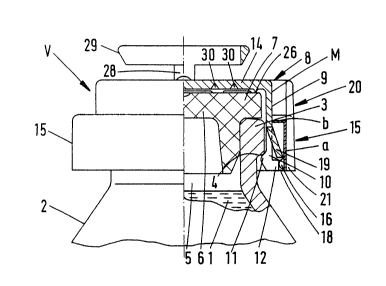
Fig. 1 is a half section through the closure cap placed
on an infusion or transfusion bottle;
Fig. 2 is a top view thereof;
Fig. 3 is a side view, seen from the direction A in Fig.
2;


20~

Fig. 4 shows the closure cap in an exploded view,
showing the bottle neck;
Fig. 5 shows the cap of the closure cap in a half
section;
Fig. 6 is an inside view thereof;
Fig. 7 is a top view of the cap with the tear tab
arranged on its top;
Fig. 8 is a section along the line VIII-VIII of Fig. 6,
in a showing considerably enlarged as compared with Fig. 6
and showing the lower section of an individual tongue;
Fig. 9 is a half section through the sliding ring;
Fig. 10 is a bottom view thereof, and
Fig. 11 is a section along the line XI-XI of Fig. 10,
showing the lower section of the locking tongue, again
considerably enlarged.
The bottle 2, which can be secured by a closure cap V
and contains an infusion or transfusion liquid 1, passes via
a conicall~ tapering section into the bottle neck 3 of
reduced cross section. The neck is developed as a so-called
beaded neck, i.e. it has peripherally an annular bead which
is produced by an accumulation of material and the lower
flank of which forms an undergrip locking shoulder 4.
The infusion or transfusion bottle, as a general rule,
consists of glass.
A stopper 6 of suitable cross section is pressed into
the mouth cavity 5 of the bottle neck 3. The stopper
consists of rubber or similar elastic material. It is a
hollow stopper the lower outer edge of which is beveled,
creating an end cone. An annular collar 7 extends over the
front end of the bottle neck 3. The front end drops slightly
outward at an acute angle. The substantially cylindrical


-- 5 --

20~

circumferential surface of the edge collar 7 is located
slightly backward with respect to the corresponding
circumferential surface of the bottle neck 3 or annular bead.
Another component of the closure cap V is a cap 8 which
is anchored on the bottle neck 3, under which it grips. This
cap consists of plastic (PP). For its anchoring, its annular
cap wall 9 is formed of resilient, i.e. outwardly springable,
individual tongues 10. These are tabs of material which are
cut from the lower edge of the cap wall 9. These tabs of
material which act like detent fingers form. within the lower
end region, an inward directed detent bead 11 the upper flank
11' of which extends in locking manner below the undergrip
locking shoulder 4.
As can be noted from the drawings (see, in particular,
Fig. 8), the individual tongues 10 are developed practically
angular in cross section. Due to the shorter outward
pointing angle leg, there results a sort of L-structure
which, with the inclusion of the accumulation of material
forming the detent bead 11, can even be referred to as a
hammerhead profile. The outwardly directed angle leg which
extends out on the back of the detent bead 11 is designated
12.
Although the individual tongues 10, as a result of the
said hammerhead profile, already have a high degree of
stability despite the relatively slight wall thickness of the
cap 8, good stability is present already solely due to the
annular arching. This stability is however further increased
by the fact that the peripheral angular space of the
individual tongues 10 is further stiffened by a ledge 13.
The latter extends axially at least over the length of the


-- 6 --

55~..

individual tongues in centered position. It terminates on
top at the height of the root of each individual tongue 10.
In order to secure the attached position shown in Fig. 1
in which the cover 14 of the cap 8 presses the annular collar
7 in sealing fashion against the end surface of the bottle
neck 3, there is provided a sliding ring 15 which
peripherally surrounds the individual tongues 10. This ring
also consists of plastic (PP~. This sliding ring in locked
position prevents the moving outward of the resilient
individual tongues 10 so that the closure cap V cannot be
easily pulled off. Therefore, there is security comparable
to the conventional flanged undergripping. To be sure, the
security position is obtained without the use of a special
device, namely simply by pushing the sliding ring from above
onto the outer wall of the cap 8 which guides the sliding
ring 15.
Specifically, the pressing part of the sliding ring
which secures the individual tongues at the back against
moving out or backward is developed as an annular rib 16
which is nose-shaped in cross section. Its vertex 17, as can
be noted from Fig. 11, is convexly rounded and is in contact
pressing position on the peripheral end surface 18 of the
angle arm 12 of the individual tongues 10 which form the
place of pressing.
For the fixing in position or securing of the sliding
ring 15 itself, the said pressing means are also utilized in
the manner that the annular rib 16 which forms the pressing
means in its turn grips below locking tongues 19 on the cap
8. The locking tongues 19, like the individual tongues 10,
are tabs cut out of the cap wall 9. They are also directed
downward, but are bent outward at an acute angle, as can be


.55~.


clearly noted from Fig. 1. The outward angle is about 20.
To be sure, the locking tongues ls are of somewhat shorter
length than the individual tongues 10 due to the position in
space of the annular rib 16 on the surface 16' of which the
free front ends of the locking tongues 19 engage. In the
drawing, the corresponding front end is directed
horizontally, while the corresponding upper flank 16' extends
obliquely inward. The angle of obliqueness of the upper
flank 16' is 30. The outer edge of the locking tongue 19
enters in knife-like manner into the inner vertex of the
annular space formed by the upper flank 16' and of the inner
surface of the sliding ring 15. Alternatively, of course,
one can also proceed in the manner that the end surface of
the locking tongues 19 sits snugly on the upper flank 16'.
The inner edge of the end surface of the locking tongues
19 terminates vertically in the same plane as the end surface
18 of the angle arm 12.
The lower flank 16 " of the annular rib 16 is developed
as run-on surface or bevel. Its outward and downward
directed inclination is 45. The sliding ring 15 is
detachable from the cap 8 by an intended breaking point 20
formed of two parallel intended break notches 21. This place
of intended breakage is oriented axially. The intended break
notches 21 are about a finger-width apart. As can be noted
particularly clearly from Fig. 9, the intended break point 21
is continued in an upward directed grip tab 22. The latter
extends over the top of a sliding ring 19 so that it can be
freely gripped. In the region of the lines of intended
breakage the annular rib 16 which otherwise passes without
interruption, is reduced in thickness. Reference is had to

Fig. 10. There, the corresponding constrictions 23 can

.,
-- 8 --

,:
,,~

20~s~ 55~..


clearly be noted on the inner side. In this way, there
remains in the annular wall only a bridge of material of
small cross section, which however is nevertheless still so
stable that it requires an intentional separating movement.
From Fig. 9 it can also be noted that the sliding ring
15 is of angular profile in cross section. The one, longer
angle arm, designated a, forms the vertical annular wall,
while the other, adjacent shorter angle arm, designated _,
which is inwardly directed on top at a right angle, is guided
by its inward directed end surface 24 on the outer surface M
of the cap 8.
The angle arm b of the sliding ring which is guided on
said outer surface M of the cap 8 however also still fulfills
another function. This consists in the creation of a mating
stop surface in combination with the attachment limitation of
the sliding ring. On the cap side, the construction is such
that the upper end surface 13' of the ledges 13 form the
vertical limitation for the sliding ring 15 in position
engaged on the cap 8. Without the ledges or their pressing
action, the sliding ring could be displaced further beyond
the pressing position. In such case, the pressing would no
longer be present and there would be a jamming and inward
pushing of the locking tongue on the inner diameter of the
sliding ring 15 which rests against the outer wall M of the
closure cap V.
The intended place of breakage 20 continues uniformly
also in the inward directed angle arm k. As guide surface
there serves approximately half the height of the cap 8,
namely extending from the roots, lying at the same height, of
the individual tongues 10 and locking tongues 19 up to the

cover 14.


204~5~S~..


In the interest of a balanced cap loading, the
individual tongues 10 and the locking tongues 9 are
distributed in alternating sequence on the circumference of
the cap 8. As a whole, there are six individual tongues 10
with a corresponding number of bent-out locking tongues 19
between them. The width of the individual tongues 10 is one-
third greater than that of the locking tongues 19. The
vertical free-cuts which divide the tongues bear the
reference number 25.
Within the vicinity of the lid-side cap edge below the
lid 14 of the cap 8, there is developed a knife-edge-like
annular seal 26 which is embedded into the surface of the
relatively soft material of the stopper 6. With respect to
its softness there are necessary values which permit the
penetration of a cannula and provide such a restoration that
the punctured opening is automatically closed again.
The corresponding access is obtained by a tear tab
formed by an approximately closed annular surface 27 in the
region of the center of the top 14 of the cap 8. The annular
surface 27 extends somewhat radially outward, forming an
axially extending pull arm 28. Adjoining the latter on its
top is a ring 29. The latter extends freely over and
parallel to the top 14 of the cap 8. As a whole, there is a
course of the ring approximately in the shape of a question
mark, defined by a pair of break grooves 30, produced upon
the injection molding, on the bottom or top of the top 14.
Fig. 5 shows them inside the cap 8 and Fig. 7, outside.
The operation, summarized briefly, is as follows:
After insertion of the stopper 6 into the mouth 5 of the
bottle 2, the cap 8 is placed thereover. Its individual

tongues 10 engage on the undergrip locking shoulder 4. This


-- 10 --

209L~55~.


is followed by the placing on of the sliding ring 15 the
displacement of which i5 limited by the end surface 13' and
by the lower side of the angle arm _. The sliding ring is
guided on the outer wall M. The annular rib 16 moves over
the back of the resilient locking tongues 19 which move back
for a short time, and it finally snaps in position below the
front end of these locking tongues lo, which move back again
into the basic position. An irreversible detent connection
is present. The vertex 17 of the annular rib 16 presses
against the back, i.e. the end surface 18, of the individual
tongues 10 so that the sliding ring 15 lies like a hoop
around the ring of individual tongues. An upward directed
pull on the closure cap V is generally not capable of
eliminating the flange-like underengagement.
For the removal of the contents, it is merely necessary,
on the other hand, to pull off the ring surface 27. There is
thus produced a central opening in the cover 14, defined by
the outer of the two concentric intended-break grooves 30,
which permits the passage of the cannula.
The features of the invention disclosed in the above
specification, drawing and claims may be of importance both
individually and in any desired combination for the reduction
to practice of the invention. All features disclosed are
essential to the invention. There is herewith included in
the disclosure of the invention also the disclosure of the
corresponding/accompanying priority papers (copy of the prior
application).


-- 11 --

Representative Drawing
A single figure which represents the drawing illustrating the invention.
Administrative Status

For a clearer understanding of the status of the application/patent presented on this page, the site Disclaimer , as well as the definitions for Patent , Administrative Status , Maintenance Fee  and Payment History  should be consulted.

Administrative Status

Title Date
Forecasted Issue Date Unavailable
(22) Filed 1991-05-14
(41) Open to Public Inspection 1991-11-16
Examination Requested 1998-05-12
Dead Application 2001-05-14

Abandonment History

Abandonment Date Reason Reinstatement Date
2000-05-15 FAILURE TO PAY APPLICATION MAINTENANCE FEE

Payment History

Fee Type Anniversary Year Due Date Amount Paid Paid Date
Application Fee $0.00 1991-05-14
Registration of a document - section 124 $0.00 1993-01-19
Maintenance Fee - Application - New Act 2 1993-05-14 $100.00 1993-03-25
Maintenance Fee - Application - New Act 3 1994-05-16 $100.00 1994-03-30
Maintenance Fee - Application - New Act 4 1995-05-15 $100.00 1995-04-27
Maintenance Fee - Application - New Act 5 1996-05-14 $150.00 1996-04-18
Maintenance Fee - Application - New Act 6 1997-05-14 $150.00 1997-04-28
Maintenance Fee - Application - New Act 7 1998-05-14 $150.00 1998-04-27
Request for Examination $400.00 1998-05-12
Maintenance Fee - Application - New Act 8 1999-05-14 $150.00 1999-04-21
Owners on Record

Note: Records showing the ownership history in alphabetical order.

Current Owners on Record
ROBERT FINKE GMBH AND CO. KG.
Past Owners on Record
SCHUMACHER, CLEMENS
Past Owners that do not appear in the "Owners on Record" listing will appear in other documentation within the application.
Documents

To view selected files, please enter reCAPTCHA code :


To view images, click a link in the Document Description column. To download the documents, select one or more checkboxes in the first column and then click the "Download Selected in PDF format (Zip Archive)" or the "Download Selected as Single PDF" button.

List of published and non-published patent-specific documents on the CPD .

If you have any difficulty accessing content, you can call the Client Service Centre at 1-866-997-1936 or send them an e-mail at CIPO Client Service Centre.


Document
Description 
Date
(yyyy-mm-dd) 
Number of pages   Size of Image (KB) 
Cover Page 1993-11-13 1 13
Abstract 1993-11-13 1 18
Claims 1993-11-13 2 66
Drawings 1993-11-13 4 110
Description 1993-11-13 11 448
Representative Drawing 1999-07-15 1 11
Assignment 1991-05-14 7 253
Prosecution-Amendment 1998-05-12 1 50
Fees 1994-03-30 1 24
Fees 1995-04-27 1 62
Fees 1996-04-19 1 59
Fees 1997-04-28 1 61
Fees 1996-05-13 1 48
Fees 1997-05-13 1 93
Fees 1993-03-25 1 27