Note: Descriptions are shown in the official language in which they were submitted.
2 ~
DI~3}IWA8~1ER D~5T13RG~T I)T8PEN~
EIELD OF THE INVENTION
This invention relates to a dispensing de~ice which
is mountable on the inside of a dishwasher and which
dispenses from a removable container a desired dose of
dishwashing detergent liquid in khe dishwasher.
BACKGROUND OF TNE INVENTION
It is generally recognized that superior cleaning of
tableware which includes dishes, flatware, glasses, cups,
mugs and the like are more rsliably or consistently
cleaned and sanitized by dishwasher machines than can be
accomplished by hand. The principle reasons for this
advantage that dishwasher machines have over hand washing
is in the use of stronger detergents and considerably
higher wash water temperatures at least during the wash
and rinse cycles. In the industrial environment, the
significant labor cost in any estahlishment requiring the
cleaning of tableware places increased demand on the use
of dishwasher machines. There is also considerable use
of such machines in most households in view of the better
cleaning performance of dishwasher and also because less
time is spent in cleaning the tableware.
Institutional dishwashing machines are operated
under very demanding conditions. The machines normally
operate with a one to two minute cycle during which the
dishes are washed and rinsed and ready for reuse. Highly
caustic dishwasher dekergents are used to obtain
meaningful cleaning within that time. In addition, it is
also necessary to use various rinse aids during the rinse
cycle in order to reduce spotting on the glassware. In
the larger institutional dishwashers, electronically
controlled pumps may be used for dispensing from outside
the dishwasher through conduits to inside the dishwasher,
the necessary quantities of dishwasher detergent and
rinse aids. Such electronically controlled dispenser
systems are fairly expensive and can only be used in an
economical manner on larger institutional dishwasher
7~ .3l$'~
equipment. Although they work very well in this
environment they do require periodic service and
attention to ensure that the correct amount of dishwasher
detergent, whether it be in liquid or slurried form, and
rinse aid are properly dispensed within the dishwasher.
By virtue of the dispenser being outside the machine, the
dishwasher has to be provided with conduits which extends
through the dishwasher tub to permit dispensing of the
desired chemicals to within the machine. As a result in
accordance with some regulatory laws, various types of
fittings are required in the line to prevent mixing of
wash liquids with fresh chemicals, solutions, detergents
and rinse aids to be introduced to the machine. All of
this adds to the complexity, cost and periodic servicing
required. However, in view of the large volume of
tableware handled by institutional machines, these costs
are relatively negligible compared to the overall
effectiveness in washing large volumes of tableware.
In other types of commercial establishments which
have less demand for tableware washing, a variety of
under the counter or above the counter dishwashers are
used. Normally these dishwashexs have a single rack of
dishes which is inserted into the machine, washed for one
or two minute cycles and withdrawn for re-use. With such
low volume or low end industrial dishwashers, the use of
electronically controlled detergent and rinse aid
dispensing machines is not cosk effective. In the past,
for such low end dishwasher machines powdered detergents
with or without rinse aids have been used. However, due
to the highly caustic nature of the powders, operators of
the machines often receive caustic burns and secondly do
not always pay the necessary attention to ensure that the
correct amount of detergent powder is included in the
machine for each cycle. A further difficulty with the use
of powders is the slow dissolution rate during the
relatively short cleaning cycle. Furthermore, powders do
s~ s~
not lend themselves to aukomatic dispensing within the
dishwasher.
Powdered dishwasher detergents also present a
problem from the standpoint of incorporation of rinse
aids. The major problem in incorporating rinse aids in
highly caustic industrial type dishwasher detergents, is
that the rinse aid is not stable in the caustic
composition, so that the effectiveness of the rinse aid
is lost during storage and before use. Hence in most
situations a separate rinse aid is used in conjunction
with powdered dishwasher deter~entsO
Liquid dishwasher detergents are best suited for use
particularly for industrial type dishwashers because of
their ready dispersability in the dishwasher water and
their relative ease of dispensing. Liquid dishwashing
detergents are therefore commonly used in the larger
capacity dishwasher machines because they may be readily
pumped to within the dishwasher. As already mentioned
however, the electronically controlled pumping systems
for dishwasher detergent liquids are not cost effective
with low end type dishwashiny machines. Furthermore, to
retrofit any type of external dispensing device requires
drilling the cabinet and dishwasher tub to provide for
installation o~ dispenser conduits to within the
dishwasher.
A further difficulty with the use of liquid
dishwasher detergents is that bulk supply of the liquid
can present problems in filling reservoirs either
positioned within the machine or on the exteriox thereof.
Spillage of the very caustic materials preæents a
considerable hazard to the operator as well as to
surroundiny equipment.
Although there are various types of dispensers
available for dispensing powder into dishwasher machines,
in view of the presence of moisture and heat in the
dishwasher, the powder dispenser has to be of a design
which avoids caking of the powders and subsequent
~J ~ J ~ ~J s~
malfunctioning of the equipment. For example, the powder
dispensing device of U.5. Patent No. 2,500,059 could not
operate in the hot moist environment within a dishwashing
machine. Similarly, the more complex electronic system of
U.S. Patent No. 4,875,607, although it would function
adequately outside of a washing machine, could not
function within the dishwashing machine because of the
moist, hot environment. As to the dispensing of liquids
to within the machine as already explained, there are the
complex electronically controlled pump systems. However,
there does not appear to be available in the marketplace
any type of liquid dispensing device which operates
consistently and may be positioned within the dishwasher.
UMMARY OF THE INVENTION
In accordance with an aspect of this invention, a
dispensing system adapted for dispensing a dose of a
liquid dishwasher chemical agent inside a dishwasher when
the dispenser is mounted inside a dishwasher, the
dispensing system comprises:
i) means for mounting the dispensing system inside a
dishwasher;
ii) a container for a liquid dishwasher chemical agent;
iii) means for dispensing from the container a dose
of a liquid dishwasher chemical agent to inside
a dishwasher.
According to another aspect of the invention, a
dispensing system adapted for dispensing a dose of a
liquid, the dispensing system comprising:
i) means for mounting the dispensing system to a
support;
li) means ~or metering a predetermined dose from a
supply of a liquid and retaining the metered dose
for dispensing;
iii) means for actuating the dose metering means to
release the retained dose of a liquid, the actuating
means being attached to the dispenser mounting means
31I~iJ~'~`J
and moveable between a first non-dispensing positivn
to a second dispensing position;
iv) the supply of a liquid being held in a container;
v) the container having an outlet ~or a liquid held in
the container, the dose metering means being
connected to the outlet and adapted to retain liquid
in the contain~r when the container is inverted ~or
operative association of the dose metering ~eans
with the actuating means in its first or second
positions;
vi) means for supporting the container in an inverted
position with the dose metering means in operative
association with the actuating means, the supportiny
means engaging a portion of the container to support
the container in the inverted position, the
supporting means being adapted to permit release of
the container when replacement o~ the container is
required, the supporting means being attached to the
dispenser mounting means.
According to another aspect of the invention, an
exchangeable container for liquid dishwasher chemical
agent is provided. The container is adapted ~or use on a
dispenser which is mounted inside a dishwasher. The
container comprises:
i) an elongated, narrow, hollow bodied portion;
ii) an outlet for the container located at a lower most
portion of the container, when the container is in
an inverted use position on a dispenser;
iii) means for metering a dose of a liquid as such liquid
would drain through the container outlet in an
inverted use position on a dispenser, the metering
means beiny connected to the container outlet and
adapted to retain li~uid in the container when in an
inverted use position on a dispenser;5 iv) the metering means has reciprocal means exterior of
the container for engagement by a dispenser of the
container whereby movement of the reciprocal means
from a first non-dispensing position to a second
dispensing position dispenses a metered dose of a
liquid.
BRIEF DESCRIP~ION OF THE DRAWINGS
Preferred embodiments of the invention are shown in
the drawings wherein:
Figure 1 is a perspective view of a dishwasher in
which the dispensing system of this invention is mounted;
Figure 2 is a perspective view of the dispensing
system according to an embodiment of this invention
demonstrating the interchangability aspect of the
dishwashing detergent liquid supply containerj
Figure 3 is an exploded perspective view showing the
mounting of the di~penser to a plate which in turn is
adapted for attachment to an interior surface of a
dishwasher;
Figure 4 shows the assembled dispensing system with
the container as attached to an interior surface of a
dishwasher;
Figure 5 is a section through the mounting plate for
the dispenser according to an embodiment of this
invention;
Figure 6 is an exploded view of the container of
this invention with the metering device attached thereto;
Figure 7 is a side elevation of an actuator for
actuating the device as mounted on the container in
accordance with the embodiment of this invention;
Figure 8 is a section through the container and
metering device with the actuator in a first non-
dispensing position;
Figure 9 i5 a section through the container and
metering device with the actuator in a second dispensing
position;
Figure 10 is a section through the container and
metering device with the actuating device returning to
the non-dispensing position;
7~ 3
Figure 11 is a section through the metering device
showing the plunger returning to the first position with
detail of the plunger sealing means;
Figure 12 is a section through the metering device
showing the plunger moving in a dispensing direction with
of detail the plunger sealing means; and
Figure 13 is a section through the container with
the metering device in the first non-dispensing position
and a cap for retaining the metering device in that non-
dispensing position;
DETAII.ED DESCRIPTION OF THE PREFERRED EMBODIMENTS
The dispensing system, according to this invention,not only lends itself for use inside dishwashers, but is
also useful in dispensing a variety of types of liquids
either to within various types of treatment machines or
within various types of treatment vessels, vats and the
like or within sinks, containers and the like which
require on an intermittent basis a predetermined dose of
treatment liquid. The dispensing system i6 adapted for
use with either an integral container for the liquid to
be dispensed or a replaceable container. The dispenser
system, when set up with an integral container, may be
discarded upon dispensing of all kreatment liquid in the
dispensing system. Alternatively, with a dispensing
system having a replaceable container, the container may
be removed and a fresh container loaded with treatment
liquid replaced on the dispenser for use in the
particular environment to which the dispensing system is
adapted.
The dispensing system, according to this invention,
is particularly suited for a reliable, easy to use
dispensing of liquid dishwasher deteryents into a variety
of dishwashers. The dispensing system is of inexpensive
construction and can be arranged within the dishwasher so
that it is readily accessible and hence easy to use by
the operator. According to a preferred aspect of the
invention, product is readily loaded into the dispenser,
providing a foolproof method of use by the operator to
ensure that consistent dishwashing is provided.
Accordingly, an aspect of the invention is shown in
the drawings which accomplishes these ~eatures, it being
understood that the dispensing system, although shown in
conjunction with an under- the-counter dishwasher, is
readily usable in all other types of dishwashers due to
its compact, slim nature. The preferred use for the
dispensing system is in the "low end" type of dishwasher
machines which are used to wash various types of
tableware in smaller establishments. It is appreciated
however that in some circumstances it may be desired to
use the dispensing system in the "high end" of
dishwashers where it is not feasible to use the standard
types of electronic metering systems. A preferred aspect
of the dispensing system of this invention, whether used
in low end or high end type dishwashers, is the feature
of the readily replaceable container for the dispenser to
provide for reliable, consistent dishwashing by the
operator. It is appreciated, however, that the container
may be an integral part of the dispensing system. This
is useful in applications where it is not desired to
replace the container with the integral system. The
container and dispenser may be discarded once all liquid
in the container is dispensed.
With reference to a preferred emhodiment of the
invention as shown in E'igure 1, a standard type of under
the counter dishwasher 10 is shown having a front door 12
to provide ~ront opening access 14 to the interior cavity
16. The interior cavity 16 is defined by a standard type
of dishwasher tub, having interior walls such as sidewall
18. The door 12 in the open position, supports a rack 20
holding a plurality of tableware in this instance,
tableware 22 which require washing within the dishwasher
10~ The rack 20 may be of the standard type for use in
conjunction with the dishwasher 10. The rack 20 is slid
from the door to within the dishwasher cavity 16 and
supported by suitable supports within the dishwa~her tub
such as ledges and the like on the tub sidewalls.
A dispensing system 24, according to this invention,
may be mounted on any suitable intexior sur~ace of the
dishwasher tu~. With this particular style o
dishwasher, it i5 convenient to mount the dispenser on
the sidewall interior surface 18. The mounting of the
dispenser will be discussed in more detail with respect
to Figures 3, 4 and 5. The dispenser is mounted in a
manner so as to be readily accessible to the operator and
to be readily viewed by the operator to determine the
volume of detergent solution remaining in the dispenser.
It is appreciated that the dispensing system,
according to this invention, may also be mounted on the
dishwasher rack or some other convenient location inside
the dishwasher. As previously mentioned, the dispenser
and container may be an integral unit which is
particularly suitable for mounting on the dishwasher
rack~ Each rack would carry an individual dispensing
system and discarded and replaced with a new dispensing
system including container when all treatment liquids in
the container are used. The rack system 20 of Figure 1
is rectangular in nature. In the forward portion of the
rack 20 in the region generally designated 21, a suitable
rectangular or cylindrical in shape dispensing system may
be mounted on the wire portions 23 of the rack. By way
of a suitable actuator, liquid in the dispenser may be
dispensed to within the dishwasher once the rack is slid
to within the dishwasher and before the door 12 is
closed.
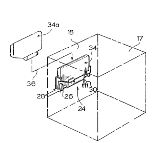
As shown in Figure 2 the dishwasher tub 17 i5 shown
in outline where the interior surface 18 has the
dispenser 24 mounted thereon. Before commencing the
cycle of the dishwasher, the dispenser is actuated to
dispense into the dishwasher tub 17, a predetermined dose
of dishwasher detergent solution. This is accomplished by
the operator pushing the actuator slide 26 in the
3~
direction of arrow 28 to cause a metered dose of
dishwasher datergant liquid to be dispensed in the
direction of arrows 30 to within the dishwasher tub 17.
The front door 12 of the dishwashex i6 then closed and by
operation of the control panel 32 of the dishwasher, the
cycle begins to clean the dishes. Normally in
institutional types of dishwashers, the cycle is in the
range of one to two minutes long. During that period
there is a wash cycle as well as a rinse cycle. The
liquid dishwasher detergent is formulated to provide for
both wash and, if desired, suitable rinsing of the dishes
during the rinse cycle.
Although discussion of various preferred embodiments
of the invention are related to the dispensing system
being used to dispense dishwasher detergent liquid, it is
understood that other types of liquid may be dispensed
depending upon the type of use to which the dispensing
system is put. For example, in using the dispenser for
dishwasher application, the liquid may be a dishwasher
chemical agent such as a descaling agent, a sanitizing
agent, a rinse agent, a deterg2nt, a water conditioning
agent and the like. Other uses may involve the
dispensing of liquids such as bactericidals, bleaching
agents, oxidizing agents, acids and the like. It is
understood that with liquid dishwasher chemical agents~
some of the compositions as a liquid will be in the form
of:
1. slurries (a solid in a liquid);
2. emulsions (a liquid in a liquid); and
3. solutions (total clissolution in the liquid of
the active components).
It is therefore understood that, with respect to
discussion of various embodiments of the invention,
liquid is intended to cover slurries, emulsion and
solutions ancl that liquid dishwasher chemical agents are
intended to cover various types o~ components used in the
dishwasher field.
~ J s;7 ~ -~
11
By virtue of a dispenser being mounted within the
dishwasher in a manner so as to be readily viewable, the
operator can determine the level of dishwasher detergent
liquid within the container 34. The dispenser is designed
so as to provide for replacement of the container 34. The
operator may readily remove container 34 and place
container 34A in the dispenser 24 as indicated by arrow
36.
Several advantages flow from the replaceable aspect
lo of the entire dispensing system or the container of
dishwasher detergent liquid for the dispensing system.
The operator is protected from exposure to very corrosive
dishwasher detergent liquids because the operator need
only remove the entire dispensing system or the empty
container and insert a new system or a full container
without having come in contact with the liquid. There is
no need for the operator to attempt to pour liquid
detergents into the dishwasher during each cycle or to
fill any type of container which may have previously been
used with dishwasher detergent liquid metering systems.
The dispenser system of this invention also avoids the
use o~ powders, which are normally dispensed to within
the dishwasher by scoop or some other type of measuring
device. In view of the ease with which particularly the
containers are replaced, there is greater impetus for the
operator to replace the container to ensure that the
desired dishwasher detergent liquid is dispensed to
within the dishwasher on a consistent basis.
With re~erence to Figure 3, further details of the
dispensiny system 24 are shown in exploded view. The
dispenser 24 comprises a replaceable container 34 which
according to this embodiment includes a dishwasher
detergent dose metering device 38. According to this
embodiment, the container 34 is inserted in the direction
of arrow 40 into a container support and dose actuating
device 42~ The dose actuating device 42 includes the
dispenser actuator mechanism 26 and a support device for
2 ~
12
the container defined by receptacle portions 44 and 46.
Device 42 also includes a back plate 48 which is adapted
for mounting to a dishwasher mounting plate 50. According
to this emhodiment, the backing plate 48 is fastened to
thP mounting plate 50 by self tapping screws 52.
The support portions 44 and 46 for the container 34
are shaped to receive portions of the container in a
manner to support it in operative association with the
dispenser actuator mechanism 26. According to this
embodiment, the receiving portions 44 and 46 are designed
to engage corner portions generally designated 54 and 56
of the container. Ledge portions 44 and 46 are shaped to
conform to ths shape of corner portions 54 and 56 of the
container. Ledge portion 44 has a bottom 58 on which the
base 60 o~ the container corner 54 rests. Upright ledge
portion 62 rests against the upright edge 64 of the
container. Slopping portion 66 of ledge portion 46
engages the bottom 68 of the container. The horizontal
base portion 70 of the ledge engages the corresponding
bottom portion 72 and the upright section 74 of the
supporting ledge 46 engages the upright edge 76 of the
container 34. Outside flanges 78 and 80 engage the outer
surface area 82 of corner portion 54 of the container.
Similarly, outside flanges 84 and 86 engage the outer
surface 88 of corner portion 56 of the container. Under
the influence of gravity, the container is thereby
steadied by the ledge support portions 44 and 46 so as to
be in operative engagement with the actuator slide in a
manner to be discussed with respect to Figures 7, 8 and
9. By virtue of this ledge support system, the container
is readily interchanged with a full container since the
ledge portions 44 and 46 releasibly engage and support
the container in the dispensing system.
As shown in Figure 4, the end view of the system
illustrates a very slender, elongated compact system. The
dishwasher tub wall 18 has the mountiny plate 50 secured
thereto by way of a suitable fastening medium 90. As
~:.J ~ JJ ~ ~ J
13
shown in Figure 5, the fastPning medium 90 may be a
pressure sensitive adhesive which firmly secures the
mounting plate 50 to the interior surface 92 of the tub
side wall 18. Also as shown in more detail in Figure 5,
the self tapping screws 52 firmly a~fixes the backing
plate 48 to the mounting plate 50. The screws 5~ do not
penetrate khrough the tub wall 18, thereby ensuring a
leak proof mounting of the dispenser system on the
interior wall 18 of the tub.
Also as shown in Figure 4, the dispensing system is
mounted in a manner so as to space the container 34
slightly from the tub wall 18 as defined by space 92. By
provision of the handgrip section generally designated
94, the operator can readily grasp by hand the container
34 to readily interchange another container in the
dispenser actuating system 42. By virtue o~ the elongated
slim structure, the container is readily grasped by the
hand-held portion 94. The hand-held portion 94 is then
defined by an undercut section 96, vertical section 9~, a
horizontal section 100 and recessed portion 102. In this
manner, the container is readily grasped for easy
replacement in the dispenser device 42 and also
facilitates handliny during packaging and uncrating.
According to a preferred embodiment of the
invention, the dose metering device is included on the
container 34 in a manner to be discussed with respect to
Figure 6. It i6 appreciated however that the dose
metering device may also be part o the dispensing
actuator system 42. With re~erence to Figure 6, the
container 34 has an outlet opening 104 as shown in
outline, which is defined by a circular outlet spout 106.
Accordiny to this preferred embodiment, a liquid return
system for the dose metering device is also provided.
Ihis return system is in the form of an aperture or
second outlet 108 as shown in outline in the container
botkcm wall 110 and is defined exteriorly by spout 112.
The metering device 114 comprises a housing 116 with a
2 ~3 ~
14
cylindrical chamber 118 defined therein. A circular bore
120 defined by annular flange 122 envelops the epout 106.
Similarly circular bore 12~ defined by annular flange 126
envelops spout 112. Hence when the container 34 is
inserted in the direction of arrows 128, the bore
surfaces 120 and 124 are dimensioned to snugly receive
the exterior surfaces of the spouts 106 and 112 to
sealingly engage those surfaces. It is appreciated then,
when required to ensure a leak-proof connection, a
flexible ring seal may be located on the spout surfaces
106 and 112.
Such inner connection of the matering device to the
container 34 is desired in instances where refillability
of the container is desired. It is appreciated, however,
that with throw-away models the metering device 114 may
be sonically welded to the container spouts 106 and 112
to form a permanent connection.
Within the cylindrical chamber 118, a plunger
arrangement 128 is inserted in the direction of arrow
130. The function of this plunger system in metering a
dose of dishwasher detergent liquid and dispensing same
shall be discussed with respect to Figures 8, 9 and 10.
With the plunger system in place in the cylindrical
chamber 118, a shipping cap 132 is provided which in
accordance with this embodiment envelopes the metering
device and the plunger to hold the plunger in place and
prevent liquid from not draining from the container
during shipping or other handling. The manner in which
this will be achieved will be discussed in more detail
with respect to Figure 13. The shipping cap is placed
over the assembled container as demonstrated in the
direction of arrow 134.
The container 34 is preferably made o~ a translucent
or transparenk material so that the liquid level 136 is
visible to the operator. There are a variety of blow
moldable plastics which are readily suited to this
application. The plastics may be of recyclable material
2 ~
or of material which permits rinsing and reuse of the
existing container. As discussed with respect to Figure
3, the support ledges 44 and 46 are shaped to permit
clear viewing o~ th~ bottom region 138 of the container
so as to visually indicate by liquid level 136 when the
container is almost empty. In this manner, indication of
replacement for the container is readily evident to the
operator.
As shown in Figure 7 in accordance with the
embodiment of this invention, the dose metering actuating
device generally designated 26 is shown as well as the
structure of the container supporting ledges 44 and 46.
The actuating device 26 is mounted to theibacking plate
48 by way oE struts 140, 142 and 144~ The actuating
device 26 includes a slide member 146 carrying a plunger
engaging device 148. The manner in which it engages the
plunger of the dose metering device shall be discussed in
more detail with respect to Figure 8. The plunger
engaging device 148 in accordance with this embodiment is
shown in more detail in Figure 3 and consists of a "U"
shaped member secured to the slide 146. Should the slide
be made from a in~ection moldable plastic, the plunger
engaging member 148 would be integrally molded therewith.
The slide 146 is secured to a reciprocal spring-loaded
guide 150 adapted for reciprocal movement within mating
channel 152. The guide 150 i5 connected to the slide 146
through the back plate 48 whereby reciprocal movement of
the guide 150 causes corresponding movement of the slide
146 in the direction of arrow 154. To provide for
automatic return of the actuator push button 156, a
spring is enclosed within the guide 150. The chamber 152
has a blind end indicated at 158. The coiled spring is
positioned within the channel 152 and within the guide
150. The guide 150 carries a spring stabilizer 160 so
that as the spring is compressed, it does not bend
radically out of shape so as to cause jamming of the
system. Hence, movement of the push button 156 in the
j!~J ~
16
direction of arrow 162, compresses the coiled spring 164
within the chamber 152 and guide 150 until the distent
end 166 of the slide 14S abuts a stop 16~. ~lence in
accordance with this dispensar system, the actuator has a
~irst non-dispensing position as defined by the plunger
engaging device being in the position shown in solid
line. However, when the actuator button 156 is moved to
position 156a,as shown is dot, and the plunger engaging
device is correspondingly moved to position 148 A as
shown in dot, the actuator is then in the second
dispensing position. By virtue of the slide mounting~ the
actuator is then allowed to reciprocate between the first
non-dispensing position and the second dispensing
position. In accordance with this preferred embodiment,
the release of the metered liquid does not commence until
the plunger has moved to the second dispensing position.
This avoids a gradual release of the dose or a
pressurized injection of the dose of li~uid. By use of a
coiled spring 164, automatic return of the actuator to
the first non-dispensing position is thus achieved, the
function of which will be described in more detail with
respect to Figure 10.
With reference to Figures 8, 9 and 10, the
dispensing of a metered dose of dishwasher detergent
liquid shall be discussed. In accordance with this
embodiment of the invention, the dose metering device 114
not only serves to meter ~rom li~uid 170 within a
container 34 the desired quantity of dishwasher detergent
liquid, but also serves to retain the liquid in the
container when it is in its inverted use position. This
is accomplished by positioning the plunger mechanism
within the metering device 114 in the first non-
dispensing position as shown in Figure ~. As already
explained with reference to Figure 6, the container has a
dishwasher detergent outlet 104 defined by spout 106~ The
metering device has a bore 120 defined by circular flange
122 for sealingly engaging the spout 106 at the interface
~d ~
17
172. Similarly return flow aperture 108 as defined by the
spout 112 is encompassed by smooth bore 124 defined by
flange 126. The smooth bore 124 is dimensioned to engage
the spout 112 to provide a leak ti.ght inter~ace at 174.
The leak tight inner connections at 172 and 174 secure
the dose metering device 114 to the container. It is
appreciated of course that for nonrefillable uses the
dose metering device may be sonically welded to the
plastic of the container as desired. The metering device
114 has a chamber 118 as defined by interior cylindrical
wall 176. The chamber 118 is open-ended at 178 as defined
by the circular open end 180. Openings 104 and 108 are in
communication with the chamber 118. The plunger device
128 defines the portion of the chamber which meters a
predetermined dose of the dishwasher detergent liquid 170
from the container 34. The plunger deviGe 128 defines a
chamber portion 182 which effects the metering of the
predetermined dose of dishwasher detergent liquid. This
portion is defined by plunger segments generally
designated 184 and 186.
The forward segment 184 of the plunger device
consists of a plunger having a front :Eace 188 and a rear
face 190. A cylindrical portion 192 is slightly less than
the interior diameter of the chamber 118. Cylindrical
portion 192 includes an annular grove 194 within which a
sealing ring 196 is provided. The sealing ring sealingly
engages the circular interior ~urface of the chamber 118
to seal and thereby prevent escape of liquid beyond the
seal 196 to the exterior of the open-ended chamber 118.
The function of the seal shall be discussed in more
details with respect to Figures 11 and 12. Attached to
the forward face 188 of the plunger is a ~utton member
198 secured to the forward face by shaft 200. With the
plunger mechanism 128 in the first non-dispensing
position, as shown in Figure 8, and by virtue of
inserting the container into the dispenser mechanism 42,
iJ
the plunger engaying yoke portion 148 fits behind the
button 198 as shown in dot at 148 in Figure 8.
The second plunger segment 186 is connected to the
first plunger segment 184 by means of a shaft 202. ~he
second segment consists of a cylindrical hollow piston
member 204 having a front face 206. The cylindrical
piston 204 has in its side walls apertures 208 to allow
liquid through aperture 108 to flow into the hollow
piston and up against the rear face 210 oP the hollow
piston as the plunger is moved from the first non-
dispensing position to the second dispensing position.
The rear portion 212 of the hollow piston abuts the rear
face 214 of the chamber to act as a stop in defining the
first non-dispensing position of the plunger mechanism.
In this way, the button 198 is sufficiently spaced from
the open end 178 of the chamber such that as the
container is placed in the receptacle portion of the
dispenser actuating device, the yoke 148 of the plunyer
engaging mechanism slides neatly behind the button 198 so
as to engage the button 198 for purposes of reciprocating
the plunger mechanism between the first and second
positions.
As the plunger mechanism is moved from the first
non-dispensing position to the second dispensing position
as shown in Figure 9, several events happen during a
movement to effect a dispensing of a predetermined dose
o~ dishwasher detergent liquid. With the chamber 182
filled wikh liquid, actuation of the button 156 of the
slide 146, moves the plunger in the direction of arrow
154. q`his is usually a fairly rapid movement, so that
piston face 206 moves across the outlet 104 and into the
region designated 216 where the perimeter 218 of the
pi~ton face is blocking or minimizing any further flow of
dishwasher detergent liquid from outlet 104 into the
chamber area now defined at 182a. As this occurs, the
seal 196 for the plunger segment 184 has moved out
through the open end 178 of the chamber until as shown in
~;J ~ 13~ ~J ~
19
Figure 9, with the piston face 206 in engagement with the
interior cylindrical surface 176 of the chamber, the
entire plunger cylindrical portion 192 is outside of the
chamber 118. With the rear face 190 in the position shown
in Figure 9, the dishwasher detergent liquid is frea to
flow in the direction o~ arrows 30 so as to be dispensed
within the dishwasher. This second dispensing position
for the plunger mechanism 1~8, is defined as shown in
Figure 7, by the disten-t end 166 of the slide abutting
the stop 168.
Depending upon the viscosity of the liquid to be
dispensed, the time during which the rear face 190 of the
plunger should remain outside of the chamber to release
the entire dose of liquid is thereby determined. For
less viscous liquids such as liquids with a viscosity
close to that of water, a very short dwell time is
required, whereas for more viscous liquids, a longer
dwell time during which the liquid drains from the
chamber 182A is required. This particular embodiment is
adapted to dispense liquids of a viscosity similar to
water so that a very short dwell time is required to
release the liquids. Hence, the spring functions in a
suitable manner such that by the time the operator has
released the actuator button, all liquid is dispensed
from the chamber 182A and the plunger mechanism can then
be returned to its non-dispensing position in a manner to
be discussed with respect to Figure 10.
It is appreciated however that with more viscous
liquids it may be desirable to provide some form of
restraint to delay returning the plunger mechanism to the
first non-dispensing position. This may be accomplished
in a variety of ways, using either compressible or non-
compressible fluids in a closed chamber behind the piston
face 210 to slowly permit the return of the plunger
mechanism to the first non-dispensing position.
Alternatively, the rate of return of the plunger
mechanism to the first non--dispensing position can be
controlled by varying the size of the second outlet 108.
The spring 164 biases the plunger to the first non~
dispensing position. Fluid~ which is moved into chamber
region 118 through second outlet 108 and in behind the
piston against face 210, is returned to within the
container through outlet 108 when the plunger moves to
the first non-dispensing position. The apertures 208 in
the piston arrangement 186 may be closed to contain the
liquid in the chamber area 118 behind the piston face
210. As will be discussed with respect to Figure 10, by
varying the si7e of the outlet 108 the rate o~ return of
the plunger mechanism can be controlled.
Chamber 182a defines the volume of the metered dose
of dishwasher detergent liquid. This is effectively the
same as the volume within the chamber 118 as defined
between faces 190 and 206 of the plunger segments 184 and
186. It is appreciated that the volume of this chamber
may be varied by changing the distance between the faces
or altering the length of the plunger cylindrical segment
192. This provides for various metered doses of
dishwasher detergent liquid as required for various
applications. Normally the movement of the plunger
mechanism from the first and second position is
su~ficiently expedient to prevent excessive drainage of
liquid from outlet 104 into chamber 182a after the
plunger seal 196 has moved beyond the open end 178 and
before the piston face 206 engages region 216 o~ the
cylindrical interior face 176 of the chamber 118.
Similarly on the return of the plunger mechanism to the
first position from the second position, the travel is
sufficiently expedient to minimize the drainage of
dishwasher detergent liquid from the container 34 into
the dishwasher.
While liquid drains from chamber 182a, in the
direction of arrows 30, air enters the chamber 182a
through opening 218. Once the plunger mechanism 128 is
21
returned to the first position, air i5 then trapped in
chamber 1~2a, the purpose of which i5 to vent to
container 34 so that the next charge of dishwasher
detergent liquid can flow into the chamber 182 when the
plunger is in the first non-dispensing position. With
reference to Figure 10, the return o~ the plunger
mechanism 128 towards the first non-dispensing position
is demonstrated by arrow 220. As shown in Figure 10/
chamber 182b commences filling with liguid detergent from
outlet 104 2S demonstrated by the direction of flow of
arrows 222. The lower region of the chamber 182b fills
with liquid detergent 170a. The detergent is contained in
this region by virtue of the rear face 190 of the plunger
segment 184 being in contact with the cylindrical
interior surface 176 of the chamber 118. At the same time
air which was contained in the chamber 182a and now 182b
bubbles upwardly in the form of bubbles 224 in the
direction of arrows 226. In this way pressure is
equalized within the container 170 to allow liquid to
flow through the outlet 104 into the chamber 182b while
the necessary air flows upwardly into the empty space
inside the container above the liquid level. It is cf
course appreciated that should additional venting for the
container be required or, because other dispensing
devices venting cannot be arranged as demonstrated in
Figure 10, a suitable check valve type mechanism may be
included in the container to permit air to flow into the
container as liquid is dispensed, but prevents flow of
liquid to the exterior of the container when liquid is up
against the venting mechanism.
To avoid the need for a tight seal of the piston 186
with the cylindrical interior of the chamber 118, liquid
is allowed to flow within the cylinder through apertures
208 against the rear face 210 of the piston. In returning
the plunger arrangement to the first non-dispensing
position, liquid behind the piston 186 is forced upwardly
in the direction of arrows 228 through the aperture 108
5 ~ ~glJ ~
22
back into the container 34, hence any liquid which leaks
between the cylindrical surface of the piston 186 and the
chamber interior wall is allowed to move freely behind
the piston face so that the force o~ the spring 16~ i5
sufficient to return the plunger to the first non-
dispensing position. Once the plunger mechanism is
returned to the position of Figure 8, the chamber 182 is
then full of dishwasher detergent liquid in readiness for
dispensing the next dose of dishwashing detergent liquid
to the inside of the di~hwasher.
As noted with respect to Figure 8, the return of the
plunger mechanism to the first non-dispensing position
under the bias of a suitable biasing device, such as
spring 164, can be controlled by modifying the piston
arrangement. The openings 208 in the piston may be
closed. Liquid is then contained in the chamber 118
behind the piston face 210. As the plunger is returned
to the first non-dispensing position, the liquid is
returned into the container in the direction of arrows
228 through second outlet 108. By decreasing the size of
opening 108, the rate at which the liquid is returned to
the container can be controlled. With more viscous
liquids, it i5 desired to have the plunger mechanism
remain for an extended period of time in the second
dispensing position. Depending upon the viscosity of the
liquid, the size or dimension of the second outlet 108
may be selected to provide a slow rate of return o~ the
viscous liquid into the container. This slow rate of
return of the liquid correspondingly provides for a
controlled slow rate of rekurn of the plunger to the
first non-dispensing position. Depending upon khe
biasing force exerted by the spring, and the size of
ouklek 108, the plunger rake of return to the first non-
dispensing position can thereby be controlled to ensure
khat when the plunger is in the second dispensing
position, all of the desired premetered dose of liquid is
dispensed.
23 ~ 3~'~
To ensure an effective seal of the plungar segment
184 with the interior 176 of the chamber 118, a wiper
seal of the type shown in Figures 11 and 12 i5 used. The
wiper seal is contained in the annular space 194 as
mounted on spindle 230. The wiper seal i5 a ring
dimensioned to engage the interior surfac2 176 of the
chamber 118 as supported by the spindle 230. The wiper
seal in the form of an annular ring 232 then slopes in
the manner shown in Figure 11 when the plunger mechanism
is returned in the direction of arrow 220. The rear face
234 of the front face 188 of the plunger supports the
sealing ring 232 as the plunger moves in the direction of
arrow 222. Conversely when the plunger moves in the
direction of arrow 154, the sealing ring 232 slopes in
the opposite direction and is supported by interior face
236 of the plunger. This type of sealing mechanism forms
an ef~ective seal regardless of the direction of travel
of the plunger and also compensates for variations in the
dimensioning of the interior surface 176 relative to the
plunger. This type of seal does not necessitate a low
tolerance in the dimensioning of the cylinder and piston
seal, so that the components may be injec~ion molded Erom
suitable plastics.
To enhance the sealing of the plunger with the
cylindrical interior face 176 of the chamber, two sealing
rings 232 may be employed. The spindle 230 may have
centrally located thereo~ a raised ridge where a sealing
ring 232 is placed on each side of the ridge. The dual
sealing action on the interior face 176 of the chamber
further enhances the sealing to retain liquid within the
container. The open ended portion 218 of the chamber may
also be chamfered to assist in the return of the plunger
to within the chamber. This facilitates the return of
the plunger particularly when two sealing rings 232 are
employed. It has also been found that with a chamfer at
the open ended portion of the chamber, the second sealing
ring provides a snap action in returning the plunger to
~J ~ J ~7 ~
24
completely within the chamber. Such snap-action closure
is particularly useful for shipping purposes to ensure
that the plunger does not move outwardly of the chamber;
it being understood, of course, that the shipping cap 240
prevents the plunger from moving outwardly o~ the chamber
to any extent which would allow lsakage. It is also
appreciated that the plunger engaging device 148 may be
chamfered slightly at its upper end to act as a lead-in
in engaging the button 128, particularly when the plunger
is in its first non-dispensing position fully seated in
the chamber as removed from the shipping package.
It is appreciated that during handling and shipping,
the plunger mechanism 128 should be retained in the first
non-dispensing position within the metering device 114.
With reference to Figure 13 and in accordance with this
embodiment, this is ensured by use of a shipping cap 132
which is dimensioned to ~it snugly over the housing 116
for the metering device. The shipping cap 132 has end
plates 238 and 240 and plate 238 abuts the corresponding
end 242 of the housing of the metering device. End plate
240 is positioned to be spaced slightly from button 198
of the plunger device 128 to hold the plunger mechanism
in the first non-dispensing position. In this way, the
seal 232 is in sealing engagement with the interior
surface 176 of the chamber 118 to prevent any leakage of
dishwasher detergent liquid from the container during
shipping and handling. once it is desired to place a
container in the dispenser, the shipping cap 132 is
removed to expose the button 128 whereby the container is
positioned in the receptacle of the dispenser actuating
mechanism in the manner discussed with respect to Figure
8. It is appreciated that other mechanisms may be used to
secure the plunger mechanism in the first non-dispensing
position. For example, a suitable security seal o~
severable material may be wrapped over the button and
secured to the housiny for the metering device. Such
severable material could be broken by the slide mechanism
i t~ Yl3 r
when the container is put in the use position on tha
dispenser actuating device.
In accordance with this discussion of preferrad
embodiments of the invention, it is appreciated that the
dispenser is particularly suited for use in conjunction
with dishwasher machines. Consistent dispensing of a
dose of dishwasher detergent and safe replaci~ility of
the detergent liquid containers are assured with each
embodiment. The operator is capable of determining upon a
glance if there is detergent in the system for dispensing
and, if not, a replacement is readily inserted. The
shipping and handling of the very caustic corrosive
dishwasher detergent liquids is insured and operator
hazards are considerably reducedl hence enhancing the use
of this system by the operator to ensure repeated
delivery of the necessary dishwasher detergent liquid to
within the machine to provide for proper washing of the
tableware. The system is compact and slim in nature so
that it can be placed or mounted on the interior surface
of a variety of types of dishwashers, whether it be on an
interior surface of the tub or on an interior surface of
the door of the dishwasher. Although a manual system has
been described with respect to the dispenser, it is
appreciated that a variety of other mechanisms may be
employed whether they be mechanical or electrical to
effect a dispensing of a metered dose of dishwasher
detergent liquid. Such mechanical devices may be
actuated by either insertion o~ the tray of tableware to
be cleaned into the dishwasher or by the closing of the
dishwasher door. Electrical devices could be used to
sense the closure of the dishwasher door or to sense
humidity or temperature within the dishwasher so as to
shi~t the plunger mechanism to dispense detergent liquid
from the container.
Although preferred embodiments of the invention have
been described herein in detail, it will be understood by
those skilled in the art that variations may be made
J~ ,r~J
26
thereto without departing from the spirit o:f the
invention or the scope of the appended claim~.