Language selection

Search

Patent 2042820 Summary

Third-party information liability

Some of the information on this Web page has been provided by external sources. The Government of Canada is not responsible for the accuracy, reliability or currency of the information supplied by external sources. Users wishing to rely upon this information should consult directly with the source of the information. Content provided by external sources is not subject to official languages, privacy and accessibility requirements.

Claims and Abstract availability

Any discrepancies in the text and image of the Claims and Abstract are due to differing posting times. Text of the Claims and Abstract are posted:

  • At the time the application is open to public inspection;
  • At the time of issue of the patent (grant).
(12) Patent Application: (11) CA 2042820
(54) English Title: HAIR FASTENING DEVICE
(54) French Title: ATTACHE POUR CHEVEUX
Status: Dead
Bibliographic Data
(51) International Patent Classification (IPC):
  • A45D 8/12 (2006.01)
  • A45D 8/16 (2006.01)
(72) Inventors :
  • WU, FU-CHI (United States of America)
  • WU, FU-CHI (United States of America)
(73) Owners :
  • WU, FU-CHI (Not Available)
  • WU, FU-CHI (United States of America)
(71) Applicants :
(74) Agent: MOFFAT & CO.
(74) Associate agent:
(45) Issued:
(22) Filed Date: 1991-05-17
(41) Open to Public Inspection: 1992-02-18
Examination requested: 1991-05-17
Availability of licence: N/A
(25) Language of filing: English

Patent Cooperation Treaty (PCT): No

(30) Application Priority Data:
Application No. Country/Territory Date
07/568,981 United States of America 1990-08-17

Abstracts

English Abstract


ABSTRACT

A toothed hair fastener having leaf-spring elements situated between one or
more of the teeth of the fastener, and suitable for both thick and thin hair.
Preferably, the leaf-springs are integrally formed as part of the toothed hair
fastener.


Claims

Note: Claims are shown in the official language in which they were submitted.


THE EMBODIMENTS OF THE INVENTION IN WHICH AN EXCLUSIVE
PROPERTY OR PRIVILEGE IS CLAIMED ARE DEFINED AS FOLLOWS:-

1. A hair fastening device including:
a. a support structure;
b. at least three spaced apart teeth fastened to the
support structure;
c. at least one leaf spring attached to one said tooth
and positioned between such tooth and an adjacent tooth,
wherein said spring has greater flexibility than said teeth
and said spring has two ends via which said spring is attached
to said one tooth.


2. The hair fastening device of claim 1, wherein there
are a plurality of said leaf springs and at least one leaf
spring is positioned between each pair of teeth.


3. The hair fastening device of claim 1, wherein at
least two leaf springs are positioned between each pair of
teeth.


4. The hair fastening device of claim 1, wherein at
least two leaf springs are positioned between each pair of
teeth having an attached leaf spring.

5. A hair fastening device including:
a. a support structure;
b. a plurality of spaced-apart teeth, fastened to the
support structure, for separating strands of hair;


c. at least one leaf spring, attached to a tooth and
positioned between such tooth and an adjacent tooth, for
clasping hair passing between such tooth and the adjacent
tooth.


6. The hair fastening device of claim 5, wherein at
least one leaf spring is positioned between each pair of
teeth.


7. The hair fastening device of claim 5, wherein at
least two leaf springs are positioned between each pair of
teeth.


8. The hair fastening device of claim 5, wherein at
least two leaf springs are positioned between each pair of
teeth having and attached leaf spring.

9. A hair fastening device including:
a. a support structure;
b. a plurality of spaced-apart teeth, fastened to the
support structure, for separating strands of hair;

c. a plurality of leaf springs, each attached to a
respective tooth and positioned between such tooth and an
adjacent tooth, for clasping hair passing between such tooth
and the adjacent tooth, wherein each said spring has greater
flexibility than said teeth, and in at least one space between
two adjacent teeth, two of said springs are each attached to
a respective tooth to face one another.


10. The hair fastening device of claim 9, wherein at
least one leaf spring is positioned between each pair of
teeth.


11. The hair fastening device of claim 9, wherein at
least two leaf springs are positioned between each pair of
teeth.


12. The hair fastening device of claim 9, wherein the
support structure is straight.


13. The hair fastening device of claim 9, wherein the
support structure is curved.


14. The hair fastening device of claim 9, wherein the
hair fastening device is a comb.


15. The hair fastening device of claim 9, wherein the
hair fastening device is a chignon pin.

16. The hair fastening device of claim 9, wherein each
leaf spring is integrally formed as part of a tooth.


17. The hair fastening device of claim 9 wherein there
is a spacing between said two springs which are positioned
between two adjacent teeth.


18. The hair fastening device of claim 17 wherein said
structure, said teeth and said springs are formed as an
integrally molded structure.


19. The hair fastening device of claim 9 wherein said
structure, said teeth and said springs are formed as an
integrally molded structure.


20. The hair fastening device of claim 18 wherein: each
said spring has two ends via which said spring is attached to
a respective tooth so that an open space exists between said
spring and said respective tooth; and two of said springs are
located in each space between two adjacent teeth.

21. A hair fastening device including:
a. a support structure;
b. at least three spaced-apart teeth, fastened to the
support structure, for separating strands of hair and;
c. a plurality of leaf springs, each attached to a
respective tooth and positioned between such tooth and an
adjacent tooth, for clasping hair passing between such tooth
and an adjacent tooth, wherein each said spring has greater
flexibility than said teeth, and in each space between two
adjacent teeth, two of said springs are each attached to a
respective tooth to face one another.


22. The hair fastening device of claim 21 wherein each
said spring has two ends via which said spring is attached to
a respective tooth.


23. The hair fastening device of claim 22 wherein each
spring is attached to a respective tooth such that an open
space exists between said spring and said respective tooth.

24. The hair fastening device of claim 21 wherein said
springs in each space between two adjacent teeth at least
approximately conform in shape to one another.

25. The hair fastening device of claim 21 wherein there
is a spacing between two springs which are positioned between
each pair of teeth.

26. The hair fastening device of claim 21 wherein said
structure, said teeth and said springs are formed as an
integrally molded structure.

27. The hair fastening device of claim 3 wherein there
is a spacing between said two springs which are positioned
between two adjacent teeth.

28. The hair fastening device of claim 9 wherein each
said spring has two ends via which said spring is attached to
a respective tooth.

29. The hair fastening device of claim 1 wherein said
structure, said teeth and said springs are formed as an
integrally molded structure.


Description

Note: Descriptions are shown in the official language in which they were submitted.


204282~


HAIR FASTE~NING DEVICE


BACKGROUND OF lHE INVENTION

1. Field of th~ Invention
This invention relates to hair fastening devices, and more particularly to
toothed hair fasteners having leaf-spring elements situated between the teeth
of the device, and suitable for both thick and thin hair.

2. Rela~ed Art
Hair combs and related hair fastening devices, such as chignon pins, hav~
traditionally been made with narrow-spaced teeth or prongs for use with thin
1~ hair, and with wide-spaced teeth for use with thick hair. Dsvices having
narrow-spaced teeth are diflicult to insert into thick hair, and devices having
wide-spaced teeth tend to be easily dislodged when used in thin hair.
Therefore, it has been common for merchants to maintain an inventory of
both types of devices to accommodate hair of different thicknesses.

Therefore, it would be desirable to provide a single type of hair fastening
device that can be used with either thin or thick hair. The present invention
provide~ such a device that can be easily and inexpensively manufactured.


. -.

2~2~


SUMWRY OF THE INVEN~lON

The invention eomprises toothed hair fastening devices having leaf-springs
situated beb~e~n one or mor0 of Ihe teeth of th~ d~vice. ThC leaf-springs are
praferably integrally form~d as part of each toothed hair fastening device.

The details of the preferred embodiment of the present invention are set forth
in the accompanyinq drawings and th~ description below. Once the details
of tho invcntion are known, numerous additional innovations and changes will
become obvious to on~ skilled in the art.

2~2~2~


BRIEF DESCRIPTION OF lHE DRAWINGS

FIGURE 1 is a front view of a curved-back hair camb embodying the present
invention.

FIGUP~E 2 is a front view of a hair fastening pin embodying the present
invention.

FIGURE 3 is a front view of a flrst straight-backed ha~r comb embodylng the
present invention.

FIGURE 4 is afront view of a second straight-backed hair comb embodying
the present invention.

FIGURE 5 is a front view of a circular hair fastening device embodying the
pr~sent invention.

FIGURE 6 is a front view of a chignon pin embodying the present invention.

Like reference numbers and designations in the drawings refer tO lik0
elements.

1282~


DETAIIE{) DESCRlPTlON OF Ti lE INVENTION

Throughout this description, the preferred embodiment and examples shown
should b~ considered as exemplars, rather than limitations on the structure
of the present invention.

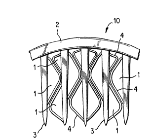
FIGURE 1 shows a front view of a curved-back hair comb 10 embodying the
pressnt invention, Thc comb 1 C includes a curved spine 2 having a number
of proj~cting teeth 3. As in known in the art, th~ comb t~eth 3 can b0
in~egrally formed with the back 2 of the comb 10, or separately manufactured
and affixed thereto. The teeth 3 are generally, but not necessarily, parallel.
Further, the teeth 3 may be straight, or curved (e.g., wavy) in any dimension.

Aff~xed at intervals to one or more of the teeth 3 are leaf-springs 4 formed of
a resilient material, such as a flexible plastic. Each leaf-spring ~ is attachedto its associated tooth 3 so as to leave open space between the l~af-spring
4 and the tooth 3. As shown in FIGURE 1, leaf-springs 4 from adiacent teeth
3 are preferably designed to approximately con~orm to each other's shape.
Such conformance leaves littlo or no gap between adjacent leaf-springs 4.

In the preferred embodiment of the invention, the leaf-springs 4 are integrally
moldod as part of the te~th 3, However, if desired, the leaf-springs 4 can bs
scparately manufactured, and affixed to thc teeth 3 in any desired fashion
(for examplc, by heat welding, gluing, or ultrasonic bonding).

The purpose of the larger teeth 3 is to "split~ relatively large groups of hair
strands apart. Becaus~ the teeth 3 of the present invention are relatively
widely spaced (comparable to th~ widely spaced teeth used for combs

20~2~2~


designed for thick hair), hair fastening devices designed in accordance with
the present inv~ntion can be inserted into thick hair relatively easily.

As the teeth 3 of a comb 10 pene~rate into a user's hair, each group of
strands of the user's hair slides in between the leaf-springs 4, which are
flexibly displaced during such insertion. The restorative spring force of
adjacent leaf-springs 4 exerts a clamping force against the hair, and thus the
leaf-springs 4 firmly clasp even thin hair.

Therefore, thfl stronger, more widely spaced teeth 3 of the comb 10 are used
to initially panetrate hair, while the leaf-springs 4 are used to clamp the comb1Q 10 to the hair and maintain the comb 10 in position after insertion.
FIGURE 2 is an alternative comb or pin-like device 20 showing an alternative
configuration of the teeth 3 and leaf-springs 4. The principle of operation of
this device 20 is the same as the curved-back comb 10 in FIGURE 1.

FIGURE 3 shows a straight-backed comb 30 i~ accordancewith thepresent
invention, having a straight back 5 rather than the curved back 20 of the
comb shown in FIGURE 1. However, the principle of operatlon of the
straight-backed comb 30 is the same as the curved-back comb 10 in
FIGURE -1 .

FIGURE 4 shows an alternative embodiment of a straight-backed comb 40
having a slightly diflerent configuration for the leaf-springs 4.

FlGURi- 6 shows a circular hair pin 50 made in accordance with the present
invention. The pin 50 comprises two pivo~ir)g semi-circular halves 6, 7 each

2~3~2~20


having a set of teeth 3 and associated leaf springs 4. A clasp or locking
m0chanism 8 is provided such that the two semi-circular halves 6, 7 can be
locked ~ogether after insertion of the device into a user's hair. The circuiar
hair pin 50 operates in the same fashion as the embodiments discussed
above, except that both of the semi-circular halves 6, 7 are inserted into the
hair (for example, when used with a "pony tail"~.

FIGURE 6 shows a chignon pin 60 having teeth 3 and leaf-springs 4 mads
in accordance with the present invention. The teeth 3 of the chignon pin 60
may also be referred to as tines or prongs. Be~veen at least some of the
1U teeth 3 are leaf-springs 4 that function in the same manner as tha leaf-
springs 4 shown in the devices of FIGURES 1-5.

The illustrated embodiments show the leaf-springs 4 as being connected to
a tooth 3 at both ends of each spring 4. However, the leaf-springs 4 can be
made such that they are not connected at one end to a tooth 3. In some
use~, this may have the drawback of catching hair either upon insertion or
withdrawal of a hair fastening device. In other uses, such a characteristic
may be desirable.

Although the illustrated embodiments show leaf-springs 4 between each pair
of teeth~ 3, it is not necessary that every pair of teeth 3 have leaf-springs 4
situated therebetween. Further, the leaf-springs 4 may be formed attached
to only one of a pair of teeth 3, as shown in FIGURES 5 and 6. In this
configuration, the restorative spring force of the singlc leaf-spring 4 ex~rts aclarnping ~orce against the hair, pressing the hair against the adjacent
opposing tooth 3.

2~~12~2~
-7-

A number of embodiments of the present invention have been described.
Nevertheless, it will be understood that various modifications may be made
without departing from the spirit and scope of the inv~ntion. For ~xample,
the spacing between adjacent paired leaf-springs 4, or between a single leaf
spring 4 and an adjacent opposing tooth 3, can be Yaried as desired during
manufacture to alter the clamping force exerted by the leaf-springs 4. The
thickness of th~ l~af-springs 4 can also b~ varied during manufac~ure to alter
the clamping force. Accordingly, it is to be understood that th~ invention is
not to be limited by a specific illustrated embodiments, but only by the scope
of the appendcd claims.

.

Representative Drawing
A single figure which represents the drawing illustrating the invention.
Administrative Status

For a clearer understanding of the status of the application/patent presented on this page, the site Disclaimer , as well as the definitions for Patent , Administrative Status , Maintenance Fee  and Payment History  should be consulted.

Administrative Status

Title Date
Forecasted Issue Date Unavailable
(22) Filed 1991-05-17
Examination Requested 1991-05-17
(41) Open to Public Inspection 1992-02-18
Dead Application 1993-11-17

Abandonment History

There is no abandonment history.

Payment History

Fee Type Anniversary Year Due Date Amount Paid Paid Date
Application Fee $0.00 1991-05-17
Owners on Record

Note: Records showing the ownership history in alphabetical order.

Current Owners on Record
WU, FU-CHI
WU, FU-CHI
Past Owners on Record
None
Past Owners that do not appear in the "Owners on Record" listing will appear in other documentation within the application.
Documents

To view selected files, please enter reCAPTCHA code :


To view images, click a link in the Document Description column. To download the documents, select one or more checkboxes in the first column and then click the "Download Selected in PDF format (Zip Archive)" or the "Download Selected as Single PDF" button.

List of published and non-published patent-specific documents on the CPD .

If you have any difficulty accessing content, you can call the Client Service Centre at 1-866-997-1936 or send them an e-mail at CIPO Client Service Centre.


Document
Description 
Date
(yyyy-mm-dd) 
Number of pages   Size of Image (KB) 
Drawings 1992-02-18 4 60
Claims 1992-02-18 5 136
Abstract 1992-02-18 1 7
Cover Page 1992-02-18 1 12
Representative Drawing 1999-04-15 1 11
Description 1992-02-18 7 181