Note: Descriptions are shown in the official language in which they were submitted.
2042833
- 1 -
A method for removing liquid from a mixture of liquid and solid matter.
The invention relates to a method for removing liquid from a mixture
of liquid and solid matter, whereby the mixture is led over one or more
casings by means of a conveyor belt which is pervious to liquid, whereby
during operation first periods, in which said casings) and said conveyor belt
are stationary with respect to each other and in which a sub-atmospheric
pressure is maintained in said casing(s), are alternated with second periods
in
which a relative movement between the conveyor belt and the casings) is
effected and the pressure in the casings) is kept at that of the surrounding
atmosphere.
Such a method can be derived from FR-A-2,194,466. Said known
device is satisfactory by itself, but in a number of cases it may be desirable
to
effect an even better removal of liquid from a mixture of liquid and solid
matter.
Various aspects of the invention are as follows:
A method for removing liquid from a mixture of liquid and solid
matter, whereby the mixture is led over one or more casings by means of a
conveyor belt which is pervious to liquid, whereby during operation first
periods, in which said casings) and said conveyor belt are stationary with
respect to each other and in which a sub-atmospheric pressure is maintained
in said casing(s), are alternated with second periods in which a relative
movement between the conveyor belt and the casings) is effected and the
pressure in the casings) is kept at that of the surrounding atmosphere,
characterized in that during said first periods the mixture is compressed by
A
2042833
la -
means of pressure rollers, so as to promote the discharge of liquid, which
pressure rollers are arranged near the casing(s), above the part of the
conveyor belt supporting the mixture and which are independently pressed
down on the mixture with an adjustable force, whilst during said second
periods the rollers do not exert a force in the direction of the conveyor belt
on
the mixture.
A device for removing liquid from a mixture of liquid and solid
matter, provided with an endless conveyor belt which is pervious to liquid
and with one or more casings over which a conveying portion of a conveyor
belt moving the mixture during operation is led, whereby means are
provided for intermittently effecting a relative movement between the casings
and the conveyor belt and a relative standstill between the casings and the
conveyor belt, as well as means for generating a sub-atmospheric pressure in
said casings) during the periods when the conveyor belt and the casings) do
not move with respect to each other, characterized in that a few rollers
extending transversely to the direction of movement are disposed above the
conveying portion of the conveyor belt, whilst means are provided by which
said rollers can be independently pushed in the direction of the conveying
portion and be moved in a direction away from the conveying portion.
By using the method according to the invention a particularly effective
removal of liquid from the mixture can be obtained during the periods when
the casings) and the belt are stationary with respect to each other, as a
result
of the sub-atmospheric pressure in the casings)
A
2042833
_ 2
and the simultaneous compression of the mixture by means of the pressure
rollers. By not exerting a force in the direction of the conveyor belt by
means
of the pressure rollers during said second periods, the casings) and the belt
can move with respect to each other, without undesirably large forces being
exerted on the parts formed by the casings) and the conveyor belt which are
moving with respect to each other, which forces might lead to excess wear
and/or rupture of the parts in question.
It is noted that from FR-A-2,168,154 a device is known which is
provided with a filter belt which moves over a trough 19. Near said trough a
few pressure rollers are disposed above the filter belt, said rollers only
being
supported on the belt under the influence of their own weight. It is not
possible hereby to release the pressure exerted on the material by the
rollers,
nor is it possible to control the pressure exerted by the rollers
independently.
Consequently such a construction will not be suitable for use in a device
wherein the belt moves over casings in which a sub-atmospheric pressure can
be generated.
A similar device is known from US-P-3,531,404. This publication does
not relate to a device in which the extraction of liquid from a mixture is
promoted by means of a vacuum either. Also with this known device the
rollers occupy a fixed position with respect to the conveyor belt, by means of
which the material to be de-watered is moved. Said publication does
mention, however, that the rollers are mounted in such a manner that it is
possible to adjust the pressure exerted by the rollers, but no means are
provided for moving the rollers, once they are arranged in a certain position,
to and fro between a position in which they exert an effective pressure on the
mixture to be de-watered and a position, in which no substantial pressure is
exerted on said mixture.
A device according to the invention, which is particularly suited for
carrying out a method according to the invention is one in which the
construction of the means for pushing the rollers in the direction of the
conveyor belt is such that the pressure exerted by a roller can be adjusted
independently of the pressure exerted by another roller.
a
2042833
2a -
When using such a device it is possible, if required, to exert additional,
independently adjustable pressures on the mixture present on the conveyor
belt, by means of the various pressure rollers, during those periods in which
a vacuum is generated in the casing(s), as a result of which a very effective
de-watering adapted to the material to be processed can be achieved.
-3-
The invention will be explained in more detail hereafter, with
reference to a few possible embodiments of a device according to the
invention diagrammatically illustrated in the accompanying Figures.
Figure 1 is a diagrammatic side elevational view of a first
embodiment of a device according to the invention.
Figure 2 is a larger-scale view of a part of the device shown in
Figure 1.
Figure 3 is a cross-sectional view of Figure 2.
Figure 4 is a diagrammatic, larger-scale view of a part of the
device shown in Figure 1, illustrating a modified embodiment.
Figure 5 is a diagrammatic side elevational view of a second
embodiment of a device according to the invention.
Figure 6 is a larger-scale cross-sectional view of a part of
Figure 5, wherein for easy reference certain parts have been left out.
Figure 7 is a side elevational view of a third possible embodi-
ment of a device according to the invention.
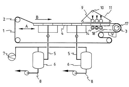
The device shown in Figure 1 comprises a endless conveyor belt 1
which is pervious to liquid, said conveyor belt being passed over guide
rollers 2 and a drive pulley 3.
The upper part of the conveyor belt 1, on which the mixture of
liquid and solid matter is present during operation, and which thus
forms the mixture-moving conveying portion of the conveyor belt, is led
over one or more casings 4 which are coupled together, said casings being
connected, by means of pipes 5, to vessels 6 in which a sub-atmospheric
pressure can be generated by means of a vacuum pump 7 connected to said
vessels. Liquid collected in said vessels 6 can be discharged via the
pipes 8. The casings 4 can be moved to and fro in the direction indicated
by the arrow A by driving means (not shown).
The construction of such a device, as far as described above, is
generally known per se.
According to the invention a plurality of rollers 9, three in the
illustrated embodiment, are provided near the downstream end of the upper
conveying portion of the conveyor belt 1. Said rollers 9 are resting on a
part of a pressure belt 11 supported by guide rollers, said part exten-
ding parallel to the upper part of the conveyor belt 1.
As is illustrated in more detail in Figures 2 and 3, each of the
CA 02042833 2001-02-14
-4-
rollers 9 is freely rotatably supported by a shaft 12. The ends of each shaft
12
are coupled to setting cylinders 13, by means of which the shaft 12, and with
it
the roller 9 supported by the shaft 12 in question, can be moved in vertical
direction.
Three supporting rollers 14 extending parallel to the rollers
9 are disposed under the ca.sing(s) 4, near the pressure rollers 9. Each
supporting roller 14 is mounted on a shaft 15. Each shaft 15 has a sprocket
wheel 16 mounted on one of its ends. An endless driving chain 18 is passed
over said sprocket wheels and over a sprocket wheel 17 coupled to the driving
drum 3, as is diagrammatically indicated in Figure 2.
Near the supporting rollers 14 a reinforcing place 18 is
provided between the supporting rollers and the bottom side of the casings) 4.
During operation the conveyor belt 1 will generally be
driven continuously by means of the driving drum 3, in such a manner that the
upper part of said conveyor belt 1 is moved in the direction according to the
arrow B. As already said before the casings) 4 are moved to and fro during
operation by driving means (not shown). When the casings move in the same
direction as the upper part of the conveyor belt 1 a sub-atmospheric pressure
will be generated in at least some of the casings) 4, so as to suck liquid
from
the mixture of liquid and solid matter present on the belt 1. During the
movement of the casings) 4, in a direction opposite the direction of movement
of the conveyor belt, generally no vacuum will be maintained in the casings)
4,
in order to prevent the conveyor belt from adhering to the casings during the
return movement, so there is intermittently a relative standstill between the
casings 4 and the conveyor belt 1 when the casings 4 and the conveyor belt 1
are moved in the same direction and a relative movement between the casings 4
and the conveyor belt 1 when the casings 4 and the conveyor belt 1 are moved
in opposite directions.
Whilst the casings 4 are moved in the same direction as the
upper part of the conveyor belt 1, the rollers 9 will be pushed downwards by
means of the setting cylinders 13, so as to exert pressure, via the pressure
belt
11, on the material present on the conveyor belt 1, in order to squeeze
moisture
from said material. The compressive force exerted on the casings) 4 is thereby
transmitted, via the plate 18, to the supporting rollers 14. The drive of said
supporting rollers by means of the chain 18 and the sprocket wheels 16 and 17
is thereby chosen such that the peripheral velocity of the parts of the
supporting
rollers 14 making contact with the plate 18 is at least substantially equal to
the
rate of displacement of the conveyor belt 1 in the direction indicated by
CA 02042833 2001-02-14
the arrow B.
During the return movement of the casings the pressure rollers 9
will be moved upwards, so as to prevent the occurrence of undesirable forces
in
the system.
Preferably the forces exerted on the pressure rollers 9 by means of
the setting cylinders 13 can be independently adjusted for each pressure
roller,
so as to be able to squeeze out the material present on the conveyor belt 1 in
the
most optimal manner.
Of course modifications and/or additions to the above-described
embodiment are possible within the spirit and scope of the invention.
Thus it is e.g. conceivable, as is also the case with similar known
devices, to drag along the casings 4 in the direction according to the arrow B
by
means of the conveyor belt 1, by the forces which are generated as a result of
the
conveyor belt being sucked against the casings) 4. Since large forces are
exerted by the pressure rollers, however, it is preferred to provide a
positive
drive for the casings 4.
Furthermore a casing 20 may be provided downstream of the
pressure rollers 9, as is diagrammatically shown in Figure 4, via which
pressur-
ized air or a suitable gas can be blown through the layer of mixture present
on
the conveyor belt 1, so as to blow off moisture present in said layer of
mixture in
this manner. The casing 20 may occupy a fixed position thereby, or be
reciprocatingly movable by means of setting cylinders, in a similar manner as
the pressure rollers 9.
Also it will be possible within the spirit and scope of the invention
to provide the pressure rollers 9 and/or the casing 20 without using the
pressure
belt 11.
With the embodiment according to Figure 5 use is made of a
number of casings 21 which are pivotally coupled together so as to form an
endless chain, said casings being passed over guide rollers 22, whereby at
least
one of said guide rollers is driven. Said device is furthermore provided with
an
endless conveyor belt or filter belt 23 whose path, guided by guide rollers
24, is
such that the upper part of said conveyor belt 23 is supported on the upper
part
of the endless chain formed by the casings 21. The bottoms of the casings 21
are
provided with perforations, which move, in the upper part of the chain formed
by the casings 21, over casings 25 disposed under said upper part, in which
casings a
-6-
sub-atmospheric pressure can be generated by means similar to those
described with reference to the first embodiment.
Near the downstream end of the upper part of the conveyor belt 23
pressure rollers 9 and a pressure belt 11 are provided again, in a
similar manner as explained with reference to the first embodiment. Near
said pressure rollers 9 the casings 21 are supported by supporting
rollers 26 provided under the casings 21 and on both sides of the
casings 25, which supporting rollers 26 can again be rotated via a chain
27.
With this known device the endless chain formed by the casings 21
and the conveyor belt 33 moves continuously in the direction according to
the arrow C, whilst a sub-atmospheric pressure is being generated in the
casings 25. By means of the rollers 9 a pressure may be exerted again, in
a similar manner as described above, on the layer of mixture present on
the upper part of the conveyor belt 23. Said pressure may be exerted
continuously or intermittently and/or different for each roller, as
required.
Figure 7 shows an embodiment wherein an endless conveyor belt 28
is moved over a number of stationary casings 29, in which a sub-atmos-
pheric pressure can be generated in a manner similar to the one described
above. The belt 28 will thereby be driven in steps in the direction
indicated by the arrow D.
In this embodiment the pressure rollers 9 and the pressure belt
11, if provided, are accommodated in a frame part which is reciproca-
tingly movable, by means of a setting mechanism 30, in the direction
according to the arrow E.
During the movement of the conveyor belt 28 in the direction
according to the arrow 0 the rollers 9 will be pressed down, in the
manner described above, on the layer of mixture which is present on the
conveyor belt 28 and which is simultaneously moved, by means of the
setting mechanism 30, in the same direction as the upper part of the
conveyor belt 28. During the standstill period of the intermittently
moving belt 28 the pressure rollers 9 will be moved upwards and the frame
part supporting the pressure rollers will be returned to its initial
position in a direction opposite the direction of movement of the upper
part of the belt 28.