Note: Descriptions are shown in the official language in which they were submitted.
2~
,:
D~cn~tiQn
:
D~SPOSABLE BLOOD S~MPLIN(:~ CARTRIDGE
This invention relates to a dev~ce for sampling blood from arteri~l
sources including a storage and valvi~g system for trans~erring the blood sampleand various fluids to a~ external analyzer for analyzing the sample.
Bacl~ground nf the Inventi~
Conventionally, blood analyzing systems include a syringe illto
which the blood is collected and all analyzer which aIlalyzes the blood for suchparame~ers as chemical composition, blood gas constituents, pH, etc. Two types
15 of syTinges h~ve been used to withdraw tbe blood from the patient's arteries. The
first type includes a vented piston arrangement wherein a needle is inserted in a
patient's artery, and the blood is forced into the syringe by the pressure
difEerential between the absolute pressure in the arte~y ~d atmospheric pressure.
Ill this first type, the air in the synnge is vented to the atmosphere. The second
20 type of syriuge includes a piston which is moved to increase the volume in the
syringe and thereby create a va~uum to suction the blood ~om the pauent.
Ollce the blood has been wilhdrawn from the patient into a svringe,
the syringe is delivered to a lab ~or analysis. Ihe sample blood is then introduced
into a co~lveMional blood analyzer. Convention,al blood analyzers include a
2S plurality of containers for respective calibrating or analyzing fluids, and a waste
container for sto;ing the spent ~uids and blood.
The problem with this arra~gement is that conventional analyzers
are too lar~e and expensive to be located at a patient's bedside. Accordingly, the
blood sample must be sent to the lab for analysis thereby re~uiling a relatively30 long p~riod of timc to obtain resu~ts. AdditioDally, conventional an~lvzers are
relatively complcx ~o operate, making bedside use impractical. For instance, thetechnician must insure that the analyzing fluids are not depleted.
Efforts have been made to simpli~r and miniaturize conventional
analyzers by pro-iding conventional analyzers with a disposable c~rlridge. The
35 car~idge maintains the level o~ the analy7.ing fluids in the ~alyzer and provides a
waste cont;liner for the spent analyzin~ fluids and blood. While such an
a~Tangemént does simplify the analyzing procedure, the disposable c~ridge is
,
., .
,, ;,, -,: .
",; ~.
:, .,, - : ' :
..
2 ~
" . `~ .
- :.
extremely e.~pensive, making the device commercially impractical. Moreover. as
with the conventional analyzer described above, a pumping system is required in
the analyzer to pump the blood and analyzing fluids through the device, thereby
adding both size and weight to the analyzer. ~ -
S
S~
The present invention resides in a blood sampling c3~ridge,
comprising a housing, a needle unit aetached to the hous~ng for withdr~wing blood
from the patient into a blood resenoir in the housing, a piston ~mit disposed in the
10 housing for pumping the blood from the blood rese~voir into a flow cell, a plurality
of ampules containing analyzing ~uids disposed in the housing for flushing thç
fluid through the analyzer during the analyzing procedure, and a waste chamber
disposed in ~he housing for storing the spent fluids. The housing includes a front
portion and a rear portion which are rotatably disposed with respect to one
15 another, the rear face of the front por~ion mating with the front face o~ the rear
portion. The front portion has a blood reservo~r, a vent line, cartIidge inlet and
outlet ports and the waste charnber; the blood resenoir, vent line and cartridgeoutlet port cornmun~cating with the rear face of the ~ont portion. The rear
portion includes a linear trench-like groove in the front face thereof which,
ZO depending on the angular orientation of the rear portion w~th respect to the front
portion, connects the bluod reservoir to either the vent line or the cartridge ou~let
por~O
Additionally, the rear portion has a plurality of ampule receiving
bores for storing the ampules and a plurality of ~uid ports for respectively
25 communicat~g the openiIlgs of ampules to the cartridge outlet port depending on
the angular pos;tion of the rear housing portion with respect to the fro~t housing
portion.
Initially, the rear portion of the housing is positioned such that the
-~ blood reservoir communicates with the vent line permit~ng the blood to be
30 withdrawn from the patient into the blood resenoir. At this stage the flow cell
ports are covered. Then the rear portion is rotated to aligIl the blood reservoir
with the cartridge outlet port such that the piston unit can pump ~he blood into the
flow cell. The flow cell ports are uncovered to ~llow access to the flow cell
connectors, 'l~ereafter, the rear portion is successively rotated to successively
JS conrlec~ each of the ampules to tbe cartridge outlet port such that the fluidco~tained in each of the ampules can be successively puunped from each of the
ampules into the flow cell.
.
: . ,, : , , ., ,, ... . , .~ :,
_ 3 ~2~
Brief Descnp~iQn~f Ih~ l~)r~w~ngs
Figure 1 is an isometric ~riew of the disposable blood sampling
cartridge according to the present invention shown in the ~ position.
Figure 2 is a cross-sec~ional view of the disposable cartndge taken
S along line 2-2 of Figure 1. .
Figure 3 is a schematic, cross-sectional view of the disposable
car~idge taken along line 3-3 of ~igure 2. ~:
Fignre 4 is a cross-sectional view of the disposable cartridge in the
60~ position taken along line 44 of Figure 1.
Figure 5 is a schematic, cross-sectional vi w of ~he disposable
cartridge taken along line 5-S of Figure 4.
Figure 6 is a cross-sectional view of the disposable cartridge in the
120C position taken along line 6-6 of Figure 1.
Figure 7 is a schematic, cross-sectional view of the disposable
cartridge taken along line 7-7 of Figure 6.
Figure 8 is a schematic, cross-sestional view of the disposable
idge iIl the 180 position taken along line 8-8 of Figure 1.
~igure 9 is a schematic, cross-sectiollal view of the disposable
ca~idge iII tbe 240 taken along li~e 9-9 of Figure 1.
Figure 10 is a schematic, cross-secional view of the disposable
cartridge in the 300 position ta3cen along line 10-10 of Figure 1.
I2~il~d Description of thelnvention
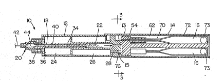
As showrl i~ Figure 1, the present invention is embodied in a blood
sampling cartridge 10 including front 12 and rear 14 cylindncal por~ons. A needle
42 projects from the ~ont portion 12, and the ~OM and rear por~ions 12, 14,
respectiYely, are rotatable with respect to each other. A cap 45 is also showIl for
coveriIlg a blood inlet 40 of the ~ont portion after the blood has been withdrawll
. and the needle removed. As explained below, rotation of the front and rear
30 portions 12, 14 with respect to each other between each of several discrete
positions controls:
(a) the ilow of blood
(i) through the needle 42 into the fro~t portion 12;
(ii) from the front por~ion 12 to a ~ow cell 11 throu~h an
ou~let port 30; and
,, " .. ::
,
. . .
., , , ~, ,
'' : ' , , :
,
- 4 204~9~
(b) the flow of spenl blood. c71ibrating, control ~nd washing
~uids from respec~e reservoirs in the re~r por~ion 14 to the
~ow cell 11 through the outle~ port 30 and into the waste
charnber in the f;ont portion 12.
The ~ow cell 11 is of co~venuonal design aud, taken alone and
apart from the blood sampling device 10, is not considered to be inventive.
Refening also now to Figure 27 the front portion 12 includes a blood
reservoir 22 connected to the needle through the blood inlet 40, a pis~on receiving
portion 24, an annular waste chamber 26, a vent line 28 com~nun~cating with the
10 waste chamber, and ~r~ridge outlet and inlet ports 30, 32, respectively. The ports
30, 32 are normally closed by a cover 100 that projects foIwardly from the rear
portion 14. The blood reservoir 22, vent line 28 and cartridge outlet port 30 each
have a lon~itudinal portion which communicates with a rear face 13 of the front
portion 12. In par~cular, the blood reservoir 22 is disposed directly on the
15 longitudi~ ds of the front portioll 12 while the vent line 28 and cartridge outlet
port 30 are radially displaced from the longitudinal axis by an equ~l distance. The
needle unit ~0 ~ncludes a needle 42 as well as a ~eedle attaching portion 44. The
needle attaching portion is desi~ed to be slid onto orle end of the tubular portion
34 of the piston unit 18 such that the drive hex 38 circumscribes the needle
20 attaching portion in the m~ner illustrated in Figure 2.
Referring also to Figure 3, the vent line 28 has a vent 76 disposed
therein which permits air to pass therethrough while preventing the passage of
blood. ~Jatural venti~g is provided through the cartridge inlet port 32 when blood
is withdrawn and through the veM line 28 when spent fluids are introduced into
25 ~e waste chamber 26.
The rea~ portion 14 is also cylindrical in shape and has a diarneter
slightly l~ger than the diarneter of the ~ont portion 12. In this manner, a ~ontend of the rear portion 14 is rotatably disposed over the rear end of the fron
portion 12 such that the front face 15 of the rear portion abuts against the rear
30 &ce 13 of the front portion 12, as illustrated in Figure 2. A groove 74 is provided
on the front face 15 of the re~r portion. The groove extends radially ~om the
cerl~er of the face, terminating short of the outer cirrumference of the rear portion
14. The groove is designed to interconnect the blood reservoir Z of the front
portion 12 to either the vent line ~8 (Figllres 2 and 3) or the cartridge outle~ port
35 30 by rotating the front portion 12 relative to the rear portion 14, as will be
describedindelailbelow.
2 i~ 8 9
The piston ur~it 18 includes an axially extending tubul~r por~ion 3~,
ge 36 and drive hex 38, as illustrated in Figure 7. The tubular por~ion 3~
defiIles the blood inlet 40 which communicates w~th the blood reservoir 2'~ of the
front portion 12. The tubular portion 34 is telescopic~lly disposed in the bore
5 forming the blood reservoir while the flange 36 is slidably disposed in the piston
receiYing portion 24 of the ~ont portio~ The piston unit 18 is actuated to e.cpel
blood ~om the blood reservoir 22, as descTibed in detail below.
As illustrated in Figure 6, the car~idge outlet port 30 is substantially
L,shaped haviAlg the above-described longitudinal porLion 31 as well as a radially
10 extending portion 33 which extends to the outer c~rcumference of the ~ront
portion. The ca;tridge i~let port 32 also extends in the radial direction and
cornmu~licates with tne waste chamber 26. The inlet port 32 is disposed adjacentthe outlet port 30 a'~lowiIlg convenient access of the ilow cell to the ports.
With reference to Figures 2 and 3, the rear portion 14 includes four
15 axially exterlding ampule ports S4 and a corresponding number of ampule
receiv~ng bores 62. Each of the ampules 16 includes a small diameter stem
portion 70 and a large diameter base portion 72. The arnpules are respec~ively
disposed irl the ampule receiving bores by respectively inserting the small
diameter p~rtions in the ampule ports. Each of the arnpules contains a different20 analyzing fiuid: wash, calibrant 1, calibrant 2, and control. The analyzing fluids
are utilized to wash, calibrate, and flush the flow cell 11 dur~ng thé blood analysis
The ampule ports 54 cornmu~icate wi1h the front ~ace 15 of the rear portion 14
and are sequentially aligned with the longitudinally disposed portion 31 ~Figure 6)
of the cartridge outlet port 30 such that the ampule ~luids can be individually
25 in~oduced into the ~ow cell 11 by successively rotating the front portion with
respect to the rear por~ion of the device a predetermined number of degrees.
Each of the ampules 16 has a ball 73 which acts as a piston to pump
the fluid ~herefrolIL Specifically, as illustrated in Figure S, the rear of eachampule is fractured using push rod 75 enabling the push rod to slide the ball in the
30 directiorl of the ampule stem 70, as illustrated by arrow B. In this manner the
fluids are pumped ~om the ampules into the flow cell via the ampule ports 54 andthe outlet port 30.
The volume of the blood reservoir is relatively small so as to
~ Lmize the amount of blood withdrawn from the pa~ient. Correspondingly, the
35 passages in the cartridge are designed to be relatively short in length a~d small in
diameter to insure that a minimal amount of blood is lost when the blood ~ows
i~ltO the flow cell so that there is a sufflcient amount of blood in the flow cell for
..
. :., , , ; .: ~ ,
. , . ., , :
..
: , .
; ,, . ,:
. .
2~2~9
: '~
analysis. A~ditionally, the front portion 12 may be manufacn~red out of a
tra~parent material to perIrlit the user to view the amount of blood in the
reservoir. Finally, an absorbent m~terial may be paclced in the w~sle chamber toabsorb the spent ~uids.
The opera~ion of the device is as follows. Initially, the front por~ion
12 a~d rear por~on 14 are rotatably aLi~ed in the manner illustrated in Figures 1,
2 and 3 with the cover 100 bloc3cing the ~ow cell ports 30, 32. For explana~ion,this position will be referred to as the 0 positiorL In the 0 positiorl, blood is
withdrawn from the patient's artery, relying on the ar~erial pressure to force the
blood into the device. As illustrated in Figures 2 and 3, the blood reservoir 22 of
the front portion 12 is cormected to the vent line 28 via the groove 74 for
permitting the air in the blood i~let to be vented through the waste chamber 26 so
as to allow the blood to enter the device. Once the flow of blood reaches the vent
76 provided at the inlet to the vent line 28 the flow of blood from the patient's
artery stops.
~hereafter, the needle is withdrawn from the patie~t, removed from
the device alld a luer loclc cover 45 (Figure 4) secured to the front end of thepiston unit 18. The device is then placed in an analyzer havulg a flow cell 11
(Figure 1). The analyzer rotates the re~r por~ion 14 of the device approximately40 with respect to the ~ont portion 12 to expose the flow cell ports 30, 32. At this
position, the flow cell 11 in the analyzer is mated to the outlel: and inlet ports 30,
32, respectively. Thereafter, the rear por~io~ is rotated all additional 20 to the
60 position to align the groove 74 with the longitudinal por~ion 31 of outlet por~
30, as illustrated in Figures 4 and ~. In this position, the blood rese~voir 2~
25 communicates with the outlet port 30 through the groove 74, long~tudinal portion
31 and radially extending por~ion 33. At this time, the analyzer slides the piston
unit 18 in the direc~ion of arrow A of Fig~lre 4 a predetermined distance causing
the blood in the blood resenroir 22 to be introduced into the flow cell. Thereafter,
the blood is analyzed.
After the blood has been analyzed, the analyzer rotates another 60
to the 120 position, as illustrated in Figures 6 and 7. In thts position~ the ampule
port 54 for the wash is aligned with the longitudinal por~ion 31 of the cartridge
outlet port 30. At this time, a mechanism in the analyzer ~actures the stem 70,
the push rod 75 in the analyzer fractures the base of the ampule and, there~fter,
35 the push rod 75 pushes the piston ball 73 in the direction illustrated by arrow B in
Figure 6 forcing the wash fluid from the ampule and into the ~low cell 11. The
wash fluid thereby ~ushes the blood from the flow cell throujgh the cartridge inlet
.,, , " . . ,, ., ,, . ~ . , , , ~ , : .
. .. .
.. . .
: ~, . . . . . ~ , .
- , . , . . :
:, - : :.
7 ~ 2~
port 32 and into the aImular waste chamber 76. Thereafter, the re~r ponion 14 isrotated another 60 to the 180 position, illus~rated in Figure 8, align~ng the
calibrant 1 ampule port 54 with the longitudinal por~on 31 of cartridge outle~ por~
30. Again, the ampule stem and base are fracnlred and the calibrant 1 ~uid forced
S into the t~ow cell ~o calibrate the a~alyzer a~d ~ush the wash ~uid from the ~ow
cell a~d into the waste chamber 26. These steps are repe~ted for the calibrant 2ampule at the 240 positioQ ~Figure 9) and the control ampule at the 300 position
(Figure 10). Fi~ally, after the con~rol fluid has been introduced into the ~ow cell
11, the analyzer rotates the rear portion another 20- to the 320~ posiuon and
10 detaches the cartridge from the ~ow cell. Thereafter, the analyzer rotates the rear
portion another 40 to the initial 0 position such that the cover 76 of the rear
portion 14 closes the flow cell ports 3Q 32, as illustrated in Figures 1 and 3. The
device c~ then be disposed of without the user ever contacting the blood or any
o the fluids.
'iVhile the preferred embodiment of the invention has been
descnbed with the disposable car~ridge storing four arnpules, it is understood that
the cartridge could store fewer or more ampules as required. Moreover, while thepreferred embodirnent describes the manner in which the c~idge is connected
to a flow ceil, it is understood that the cart~idge could be connected to any
20 appropnate analyzing device. Furthermore, while the invention has been
described with reference to withdrawing blood ~om an artery and the subsequent
analysis of the blood, it is unders~ood that the device could be used to withdraw
and analyze any fluid ~om a pressur~zed source.
. . .: . ,: .,
., . , . ' ' ,