Note: Descriptions are shown in the official language in which they were submitted.
1
OPTIMIZED 18-PULSE TYPE ACjDC, OR
DC/AC, CON~lERTER SYSTEM
The invention relates to static AC-to-DC
converters, such as can be used for AC or DC motors.
One main problem with static AC-to-DC con
verters, such as can be used for AC or DC motors, is the
generation of harmonics on the AC lines, which are caused
by the rectification process. Another problem is cost.
The use of transformers and filtering inductances, the
rating involved, all require a minimization of components,
windings and rectifying devices without losing the
benefits of the overall system.
It has been shaven in U.S. Patent No. 4,876,634
how a multiphase ACJDC converter can be designed with a
single transformer having successive tappings drawn from a
polygonal succession of long and short windings, the
difference between outputted currents being derived from
the tappings.
The present invention resides in an 18-pulse
converter system which has optimized structural and
functional characteristics. It involves three 6-pulse
rectifier bridges directly connected in parallel with the
DC terminals, two of the bridges aperating under respec-
tive +40 degree and -40 degree phase shift relative to the
AC lines, and the third or central bridge being directly
connected to the AC lines, the rectifiers being controlled
z5 for 40-degree current conduction. The invention can be
applied to five of such 3-phase rectifier bridges, for a
30-pulse system wherein the displacements are ~48°;
2~43~~~
2
:~24' relative to the central bridge. The invention is
applicable, in the same vein, to a 7-bridge pulse system,
to a nine-bridge pulse system, or more.
The invention relates to an 18-pulse AC-to-DC
converter arrangement using special autotransformer
connections with an appropriate phase shift and a selected
conduction angle in order to eliminate the need for
interphase transformers. This arrangement, when combined
with appropriate AC line reactances, leads to the genera
Lion of input line harmonid curxents in the AC lines which
are easily reduced to less than 1~% of the fundamental
current, a substantial improvement over the prior art.
Where the harmonic currents generated by an AC-to-DC
converter must be reduced to values lower than those
attainable with a 12-pulse arrangement, this particular
18-pulse design becomes desirable. This approach rests
upon the observation that the idealized harmonic currents
have frequencies of (18 k ~1j with amplitudes of
1/(18 k ~1). Prior art 18-pulse techniques have
encountered practical connection difficulties because of
the large rating of associated phase-shifting and inter-
phase transformers.
Three-phase rectifier bridge arrangements
typically involve a single 3-pulse converter group
combining three SCR devices, or 3 diodes, with a 120°
period of current conduction. With this approach,
however, there will be a need for an interphase trans-
former and for providing a neutral reference point between
the bridges. The present invention no longer requires an
~ interphase transformer, nor a neutral reference point
between the rectifier bridges.
A more complete understanding of the invention
may be had from the following description of a preferred
embodiment, given by way of example and to be read in
conjunction with the accompanying drawings wherein:
Figure 1 shows a 3-pulse converter system formed
with a single rectifier group with a neutral line return
~~~3~~4
3
for the three AC phases, in an unsmoothed DC current
operation;
Figure 2 shows a system combining two 3-pulse
converters formed with two groups of rectifiers and a
neutral line return for the three AC phases, in an
unsmaothed DC current operation
Figure 3 shows a system using two 3-pulse
rectifier groups with a zig-zag interphase transformer
providing a neutral point other than the supply source;
Figure 4; which is prior art, shows the use of
three 6-pulserectifier bridges staggered at 20 degrees
phase shift and with interphase transformers;
Figure 5, which is prier art as taken from U.S.
Patent No. 4,876,634, shows an 18-pulse converter using a
dual phase shift autotransformer, also combined with three
6-pulse rectifier bridges staggered at 20 degrees and
using interphase transformers;
Figure 6 is a polygonal representation of the
dual shift autotransformer of Figure 5;
Figure 7 illustrates the 18-pulse converter
according to the invention in an embodiment using three
parallel 6-pulse rectifier bridges, two of them under two
separate transformers at + and -40 degrees, respectively:
Figure 8 illustrates a second embodiment of the
invention wherein a single transformer is coupled to the
three parallel 6-pulse rectifier bridges for generating
pulses under ~40 degrees to a corresponding one of two of
the bridges and a 0-degree phase shift to the third
bridge;
Figures 9 and 10 show how, in the absence of a
interphase transformer, smoothing inductances are as-
sociated with the three rectifier bridges of Figures 7 and
8 for high frequency noise elimination;
Figure 11 is a diagram matching Figure 7 to show
the two delta-transformers shifted at + and -40 degrees
relative to a common and central delta winding, according
to the first embodiment of the 18-pulse converter system
of the present invention:
~0~~~~y
4
Figure 12 is a diagram matching Figure 8 to show
a single autotransformer of the differential delta type,
as used according to the second embodiment of the 18-pulse
converter system of the present invention;
Figure 13 is a representation of the three
parallel 6-pulse rectifier bridges associated Figures 11
and 12:
Figure 14 illustrates the winding distribution
according,to the embodiment of Figure 12;
'Figures 15 and 16 illustrate with curves the
input current and voltage waveforms obtained with two
different values of the inductance components used in the
rectifier bridges of Figure 13.
Figures 17, 18, and 19 are illustrating modifi
cations to the winding distribution shown in Figure 14
according to three respective embodiments of the
invention.
Referring to Figure 1, a basic 3-phase rectifier
group is shown which, because it lacks smoothing inductors
on the DC side, allows a significant ripple amount on the
DC Load. This group includes three SCR devices T1, T2, T3
connected to the AC power supply lines L1, L2, L3 through
inductances L. Their cowman junction point CM is con-
nected to the positive DC terminal TA. The neutral return
line is TN derived from the DC terminal TB. Between the
two DC terminals are a capacitor C and a resistor R, as
generally known. The system operates to convert AC power
into DC power or, conversely, DC power into AC power,
depending upon where the supply and the load is. The line
currents are shown applied through the inductance L so as
to limit the rate of change of current and provide some
reduction in the line current harmonics. The AC currents,
such as i1 on Figure 1, contain a DC component and a
significant amount of third harmonic current. Although
this is a workable circuit, it is rarely used for higher
power applications because of the distortion and the
unfavorable loading exerted upon the supply.
2~430~~
Figure 2 shows two such "building blocks°, T1,
T2, T3, and T'1, T'2, T'3 with their common junction
points CM, CM', respectively, and a common neutral point N
(located between two capacitors C and C'j far the return
5 neutral line LN. This common neutral connection is used
so as to eliminate the DC component in the supply.
Nevertheless, there remains a large third harmonic
component of current drawn from the AC source. By provid-
ing a neutral point N which does not return to the AC
power .supply, the third harmonic no longer circulates
through the AC source. This is shown on Figure 3 through
the provision of a zig-zag interphase transformer TNF with
primary windings Wl, W2, W3 associated with the three AC
lines L1, L2, L3 and criss-crossed secondary windings W'1,
W'2 and W'3 converging, via line TN, with the neutral N
located at the center point between capacitors C and C'.
However, a significant third harmonic component of current
still flows through the center point N.
Another solution, shown by Figure 4, consists in
using three ''building blocks", instead of the two shown in
Figure 3. Figure 4 shows three 6-pulse rectifier bridges
BR#1, BR#2 and BR~3, as disclosed in U.S. Patent No.
4,876,634. The rectifiers are controlled under 120-degree
current conduction, and the bridges are staggered by a 20-
degree phase shift regarding the incoming power supply
voltages. They are interconnected at both ends with an
interphase transformer--one with the positive DC terminal
TP, the other with the negative DC terminal TN--as shown
in Figure 4. This helps provide a common neutral point
like with the approach of Figure 3.
Figure 5 shows as prior art an 18-pulse con-
verter disclosed in U.S. Patent No 4,876,634. This con-
verter operates with a polygonal transformer placing each
of the lines 1, 2, 3 (for bridge BR 3), 1', 2', 3' (for
bridge R 2) and 1", 2", 3'° (for bridge BR 1) at a
relative phase shift of 20 degrees, and the SCR devices
are controlled for 120 degrees of conduction. This
polygonal solution is more generally shown in Figure 6
~04~0~4
6
with the algebraic sum indicated with the outgoing current
(I1, I2, I3) at each tapping (P, Q, R, for bridge BR f~1
and P', Q', R' for bridge BR ), the corresponding phase
shift being ~ (as given by the windings), a positive
a
voltage phase shift of +~ for PQ, and a negative voltage
phase shift of -ø~ relative for GH, where a pair of AC
lines is connected. However, as shown in Figure 5, like
in Figure 4, interphase transformers are used in order to
establish neutral points on either side of the DC ter-
~10 . urinals. This was the approach with a + and -~ degrees
phase shift between two bridges and a 120-degree conduc-
tion of current on the rectifiers.
In contrast, with the present invention, the
three 6-pulse rectifier bridges are directly connected in
parallel across the two DC terminals. Two of the bridges
are now under opposite + and -40 degrees phase shift, the
third being centrally disposed with zero degree--thus, in
phase with the AC lines. Two embodiments are proposed
with this approach, as seen with Figures 7 and 8.
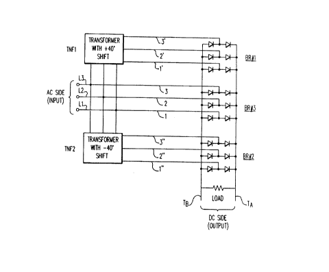
Referring to Figure 7, two transformers TNF1 and
TNF2--one at -40' phase shift, the other at +40° phase
shift relative to the AC voltage of the AC lines L1, L2,
L3--are coupled to respective rectifier bridges BR 1 and
BR 2 by corresponding lines 1', 2', 3' and 1", 2", 3",
respectively. AC lines L1, L2, L3 are directly applied by
lines 1, 2, 3 to a third rectifier bridge R 3. Thus,
like in Figure 3, the AC side is with lines L1, L2, L3,
whereas, the DC side is between terminals TA and TB at the
common terminals of the bridges.
3 0 Referring to Figure 8, another embodiment is
shown with a single transformer NF interposed between the
three bridges HR #1, BR , and BR 3 on one side and
lines L1, L2, L3, on the other side. Again, transformer
TNF will provide + and -40° phase shifts between lines
1', 2', 3' to bridge BR ~1 and lines 1", 2", 3" to bridge
BR ~2 relative to a 0-degree phase shift for lines
1, 2, 3, from L1, L2, L3.
As shown in Figures 7 and 8, there is no
interphase transformer needed on the rectifier bridge side
and no neutral point to be sought for. As a result, each
set of rectifier bridge has in common the same individual
pairs of serially-connected rectifiers across the two DC
terminals and with their midpoint connected' to the
incoming (or outgoing) AC line. All that is required is a
filtering inductance L in order to eliminate any high
frequency component on lines l, 2, 3: 1', 2', 3'; and
1", 2", 3" of the rectifier bridges. Tn Figure 9, each
line (1, 2, 3; 1', 2', 3'; 1°', 2", 3") carries an induc-
tance L. In Figure 10, two inductances L and L' are
inserted on each side of the corresponding bridge and line
between terminals TA and TB.
Figure 11 is a diagram related to the first
embodiment of the invention. It shows the voltage vector
sets of two transformers (I at +40° phase shift, and II
at -40° phase shift), the primary set being shown as a
delta diagram at O degrees phase shift, thus, in between.
Points l, 2, 3 go to bridge B 3; points 4', 5', 6' go to
bridge BR #2; and points 4, 5, 6 go to bridge BR 1.
Figure 12 shows the voltage vectors associated
with a single transformer approach in the case of a
differential delta, which relates to the second embodiment
of the invention. A 18-pulse converter system is shown
having the optimized design for such a system. About the
central delta 1, 2, 3 are placed, with a single trans-
former: points 4, 5, 6 at a phase shift of +40° and
going to bridge BR ; tappings 4', 5', 6' at a phase
shift of -40° and going to bridge BR ~2.
Figure 13 shows the three bridges--BR 1, B 2,
BR ~3-- in parallel between the two DC terminals TA, TB
and connected individually to the corresponding nine AC
lines (1 to 9). There is no interphase transfarmer. In
order to reduce the high frequency current, on each line
has been interposed an inductor L, and on the DC side an
inductor Ldc before the capacitor C, and a variable
resistor Rdc which characterize the DC load.
~a4~o~4
8
Figure 14 is the differential delta transformer
design matching the general diagram of Figure 12. WA, WB,
WC, disposed about AC lines tappings I, G, H, are the
central windings; in fact, the primary windings if the
input comes from the AC side. The secondary windings for
one of the two bridges, HR #1 and BR ~'2, are for +40'
phase shift: W'A1 and W'B2 associated with tapping 3
(apex I) opposite to winding WA: W'C1 and W'A2 associated
with tapping 2 (apex G) opposite to winding WC; and W'B1
and W'C2 for tapping 1 (apex H) opposite to winding WB.
W'B2, W'A2 and W'C2 are coupled with windings WB, WA and
WC, respectively, while windings W'A1, W'B1 and W'C1 are
coupled to windings WA, WB, WC, respectively. The same
can be said for the -40° phase shift pairs of windings
WA1 arid WC2 (apex I), WC1 and WB2 (apex G), WB1 and WA2
(apex H). The sizes of the windings are, typically, 58
turns for WA, WB or WC; 17 turns for WA1, W'A1, WB1, W'B1,
WC1 and W'C1: 9 turns for WA2, W'A2, WB2, W'B2, WC2, W'C2.
Another possible set of windings would be 65, 19 and 10
~ 20 for the respective number of turns for the main, inter-
mediate, and smallest windings.
To explain the performance of the + and -40°
phase shift relative to the central triangle 1, 2, 3, it
is noted that the third harmonic has a zera sequence,
while no phase shift does occur as it passes through the
transformer. Thus, if the third harmonic current from the
converter directly connected to the source is assumed to
be at zero degrees phase, the leading (+40°) converter
will have third harmonic current at 3 x 40°, i.e. 120°,
whereas the lag converter (-40°) will have third harmonic
current at 3 X -40°, i.e. -120°. Thus, the 3-phase set
of third harmonic currents cancels and there is no
resultant third harmonic drawn-from the source. Similar-
ly, the negative and positive sequence sets of 5, 7, 11,
l3 harmonics are phase-shifted as they pass through the
transformer. The negative sequence shifts through an
angle opposite to that of the positive sequence. For
example, considering the fifth harmonic in the +40°
ZO~~~~
9
transformer, the phase shift, with respect to the source,
is (5 X 40°) +40°, i.e. 240°. Likewise, in the -
40° shift
transformer, it is (5 X -40) -40°, i.e. -240°. Thus, the
three sets of fifth harmonic currents sum to zero from the
source. Similar reasoning leads to observe that there is
also an elimination of the 7, 11, 13 harmonics.
Considering the central 6-pulse rectifier
bridge, a 30-pulse converter system can be designed under
the same principle by adding four instead of two sym
metrically shifted bridges in conjunction with a bridge
having no phase shift. In such case, two will be at + and
-48 degrees phase shift, two will be at + and -24 degrees
phase shift, and one will be at zero degree phase shift.
one can go higher by using 7 bridges, instead of 5;
namely, 1 + 6-pulse bridges.
Figures 15 and 16 represent the line-to-neutral
voltage at the transformer output (V) and the flowing
current IL for (1) L = 0.003% and Ldc/Rdc = l,2ms: and
(2) Ldc = 0, both in the case of Figure 13.
Figure 17 is like Figure 14, but modified by the
adjunction of a winding WD placed as an extension of each
side (WA, WB, or WC) of the triangle GHI. The three AC
lines 1, 2, 3 are connected to one end of the added
windings WD, respectively, while the other end thereof is
connected to an associated apex of the triangle. The
effect is to reduce the DC output to the extent of the
ampere-turns of the added winding WD.
Figure 18 is like Figure 14, but instead of
decreasing the DC output, a winding WD is added in such a
way that the DC output is increased. This effect, the AC
lines 1, 2, 3, instead of being connected directly to the
respective apices of the triangle GHI, they axe connected
to a tapping of the main delta windings. Instead of a
full delta winding WA, WB or WC, as in Figure 14, such
winding is merely a fraction of the main triangle winding,
and the complementary fraction on the triangle is the
winding WD of Figure 17, used now as a subtrahend.
2~~3~~~
to
Figure 19 shows an alternative arrangement for
the winding system of Figure 14, regarding the pairs of
windings creating a 40' phase shift in either direction
(W'C2, W'B1 and WB1, WA2 for tapping 1: W'A2, W'C1 and
WCl, WB2 for tapping 2; or W'B2, W'A1 and WA1, WC2 for
tapping 3). Windings WA2 and W'A2 which are closest to
the main winding WA, to which they are coupled from either
end, are now inserted between a corresponding end of WA
and the associated apex of the main triangle. The same is
1o done for wB2 and W'B2 regarding main winding WB, and also
for WC2 and W'C2 regarding main winding WC. The com-
plementary winding of each pair, thus the one (WB1 and
W'B1 for apex H, or WC1 and W'C1 for apex G, or WA1 and
w'A1 for apex I) which is remote from the main winding
(WB, WC, or WA) to which it is coupled, is branched to the
nodal point between the adjacent main winding (WA and WC
for apex H, WB and WA for apex G and WC and WB for
apex I), and the inserted winding (WA2 with WA for WB1,
W'C2 With WC for W'B1; W'A2 with WA for W'C1, WB2 with WB
for WC1, etc.). For more generalization, the embodiment
of Figure 19 also shows a winding WD being inserted on
each apex of the triangle with the respective AC lines
1, 2, 3.