Note: Descriptions are shown in the official language in which they were submitted.
Zo X30 ~a
- 1 -
METHOD AND APPARATUS FOR MEASURING CROSS-TOE
BACKGROUND OF THE INVENTION
The present invention relates to automobile
wheel alignment systems. In particular, the invention
relates to a method and apparatus for measuring a cross
toe angle in a wheel alignment system.
Proper alignment of wheels in an automotive
vehicle is important for proper handling of the vehicle
and proper tire wear. In addition, the proper alignment
of the wheels will decrease fuel consumption as well as
increase vehicle safety. The wheel alignment parameters
which are measured and adjusted in order to achieve
proper wheel alignment are camber, caster, steering axis
inclination and toe.
The toe angle of a wheel, at a specified wheel
load or relative position of the wheel center with
respect to a sprung mass, is the angle between a
longitudinal axis and a line of intersection of wheel
plane and road surface. The wheel is "toed-in" if the
forward portion of the wheel is turned toward a central
longitudinal axis of the vehicle, and "toed-out" if
turned away. Accurate toe adjustment cannot be attained
without properly calibrated measuring instruments.
Camber is defined as the angle which the wheel
makes with respect to a vertical plane when looking at
the wheel from either the front or the rear of the
automobile. Any wheel of an automobile can have camber.
Caster is an angle which the steering axis of
a steerable wheel (typically one of the front wheels
makes with respect to the vertical plane which is
perpendicular to the longitudinal direction of the
automobile.
Steering axis inclination (SAI) is the
inclination of the steering axis with respect to a
vertical plane which is parallel to the longitudinal
direction of the automobile.
20 430 78
-2-
Toe was originally defined as the difference
of the distance between the front edges of two opposite
wheels and the distance between the rear edges of the
same two wheels. Toe can also be defined in terms of an
angular relationship of the plane of a wheel
(perpendicular to its turning axis) relative to a
predetermined longitudinal vehicle axis. When the
forwardmost portions of a pair of adjacent wheels are
closer together than the rear portions of those wheels,
they are commonly referred to as in a "toe-in"
condition. When the rear portions of wheels are closer
together than the front portions, the condition is
commonly referred to as "toe-out."
Camber is a tire wearing angle and also
affects handling of the automobile. Caster and SAI do
not affect tire wear, but are important for directional
control. Toe is a tire wearing angle and also affects
the position of the steering wheel required in order to
maintain the automobile along a straight line.
Wheel alignment in an automobile wheel
alignment system can be measured with angle sensors
which use a light source and a light sensor mounted on
head units which are coupled to the wheels of the
automobile. The light source is aimed at the sensor and
the sensor provides an output which represents an
angular relationship between the sensor and the light
source.
In measuring toe, however, if the light source
or the sensor is tilted out of a horizontal plane, the
tilt introduces an error into cross-toe angle
measurements. (Cross-toe angle measurement refers to the
toe angle measurement of an individual wheel).
It is desirable to lower the head units so
that light from the light source is not blocked by
obstructions such as front end air spoilers which may be
present on, for example, a sports car. To clear an
20 430 78
-3-
obstruction, typically a "drop block" is used by an
operator of the automobile wheel alignment system. Drop
blocks are used to couple the head units to the front
wheels of the automobile under test. Drop blocks allow
the head unit to be lowered in a vertical plane where an
axis of the head unit remains parallel, although no
longer co-axial, with an axis of the wheel. However, a
minor deformity in the drop block arising during
manufacturing or field use can introduce an error into
alignment measurements. The drop blocks are also
cumbersome and time consuming for the system operator to
use.
Cross-toe angle sensors must also be leveled
in a horizontal plane to obtain accurate cross-toe
alignment measurements. Both with and without the use
of drop blocks, the system operator must precisely align
the head units in the horizontal plane. This is a
source of errors in the alignment measurements, and is
also time consuming for the operator.
There is continuing need for improved angle
measurement systems which are easy for an operator to
use and which provide more accurate measurements.
SUMMARY OF THE INVENTION
The present invention provides a wheel
alignment system for measuring the angular relationship
between the wheels of an automotive vehicle. More
specifically, the invention provides a method and
apparatus of measuring cross-toe angle in an automobile
wheel alignment system which is easier to use and less
susceptible to error.
In the present invention, the front head units
can be tilted at an angle relative to the horizontal
plane, and any errors this introduces into the cross-toe
angle measurements are cancelled. The ability to tilt
the front head units provided by the present invention,
allows an operator to tilt the front head units to avoid
20 430 78
-4-
obstacles to the cross-toe light beams, such as front
end spoilers. Furthermore, the present invention allows
an operator to obtain cross-toe angle measurements
without the need to precisely level the front end head
units in the horizontal plane, as required in prior art
designs. This feature saves time for the system
operator, avoids the use of drop blocks, and reduces the
chance of an error in cross-toe angle measurements.
The invention includes four head units for
mounting to the front left and right wheels, and rear
left and right wheels of an automotive vehicle and a
controller for operating the head units. Light beams
are sent from front to back and back to front by each
pair of left front and back and right front and back
head units. Left and right front head units provide
cross-toe measurements using front left to right and
front right to left light beams.
If the front left or right head unit is tilted
out of the horizontal plane, an error is introduced into
the cross-toe angle measurement. In the present
invention, the angle of the front left and right head
units are measured relative to the horizontal plane
using level (pitch) sensors. The outputs of the level
sensors are received by the controller which calculates
a correction factor. The controller uses this
correction factor to remove the error introduced into
the cross-toe measurement.
BRIEF DESCRIPTION OF THE DRAWINGS
Fig. 1 is a perspective view of the alignment
apparatus of the present invention.
Fig. 2 is a perspective view of an angle
sensor.
Fig. 3 is a block diagram of a wheel alignment
system made in accordance with the present invention.
Fig. 4 is a side view of a head unit used in
the present invention.
20 430 78
Fig. 5A and 5B are top and side views,
respectively, of the left and right front wheels of an
automobile and the left and right front head units used in
the present invention.
Fig. 6 is a geometrical representation of a side
view of the left and right front head units.
Fig. 7 is a geometrical representation of a side
view of the left and right front head units.
Fig. 8 is a geometrical representation of a front
~o view of one of the head units.
Fig. 9 is a plan view of a slit and a light
sensor used in an angle sensor in accordance with the
present invention.
~5 DETAILED DESCRIPTION OF THE PREFERRED EMBODIMENTS
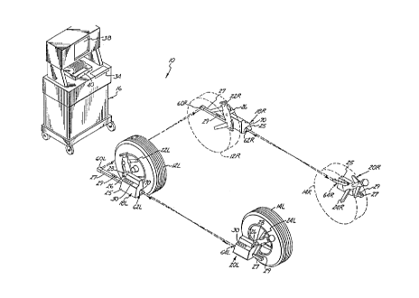
In Fig. 1, wheel alignment system 10 of the
present invention is used to measure the alignment of left
front wheel 12L, right front wheel 12R (shown in phantom) ,
left rear wheel 14L and right rear wheel 14R (shown in
zo phantom) of an automotive vehicle. For clarity, the
remaining portions of the vehicle are not shown. System 10
includes a main console 16, left and right front head units
18L and 18R, and left and right rear head units 20L and
20R. Head units 18L, 18R, 20L and 20R are connected to
zs main console 16 by cables (not shown).
Head units 18L, 18R, 20L and 20R are supported on
wheels 12L, 12R, 14L and 14R by rim clamps 22L, 22R, 24L
and 24R, respectively. Rim clamps 22L, 22R, 24L and 24R
are self-centering, four-leg rim clamps which fit a wide
3o range of different wheel sizes without the need for special
adapters. Each head unit (18L, 18R, 20L, 20R) includes a
housing 25, a sleeve 26 and an arm 27. Sleeve 26 mounts
over a spindle of the corresponding rim clamp. Each head
unit (18L, 18R, 20L, 20R) is locked into position on the
35 spindle of the corresponding rim clamp (22L, 22R, 24L,
.5
-6- 2043078
24R) by spindle clamp 28. A set of switches 30 on housing
25 allows the mechanic to signal main console 16 that a
measurement is made and to respond to messages displayed by
main console 16.
s Main console 16 includes keyboard 34 as an input
device and has CRT display 38 and printer 40 as output
devices. A power supply (not shown), which is located
within main console 16, supplies power to a computer (not
shown in Fig. 1) and its input and output devices, and also
~o supplies power to head units 18L, 18R, 20L and 20R.
Main console 16 supplies data and instructions to
the head units 18L, 18R, 20L and 20R and receives wheel
alignment measurement values from each of the head units.
Based upon these measurement values, computer 32 provides
~5 wheel alignment output values and other information to the
operator through CRT display 38 and printer 40.
In wheel alignment system 10 shown in Fig. 1,
there are a total of six angle sensor units used to measure
toe angles. Front left head unit 18L carries a left-to-
zo right sensor 60L and a front-to-rear sensor 62L. Left rear
head unit 20L carries a rear-to-front angle sensor 64L.
The angle sensor units are arranged to operate in
pairs . Sensors 60L and 60R are mounted at the front ends
of arms 27 of front head units 18L and 18R and face one
z5 another. Sensor 62L is mounted at the rear end of housing
25 of head unit 18L and faces sensor 64L which is mounted
at the front end of head unit 20L. Similarly, sensor 62R
of head unit 18R faces sensor 64R of head unit 20R.
Fig. 2 is a perspective view of an angle
3o sensor 66. Sensor 66 comprises a light source 68 and
an optical bench 70. Light source 68 is coupled to
one head unit, 18L for example, and optical bench 70 is
20 4~ 30 78
_7_
mounted to another head unit, 18R for example. In such
a configuration, angle sensor 66 measures cross-toe
angle.
Optical bench 70 includes linear CCD 72 and
frame 74. Frame 74 includes a mask 76, which defines a
slit 78. Slit 78 is at a right angle to linear CCD 72.
Slit 78 allows a portion of the light from light source
68 to fall upon linear CCD 72. The remaining portion of
the light from light source 68 directed at linear CCD 72
is blocked by mask 76. Fig. 2 shows the relationship
between light source 68 and optical bench 70 at an angle
of 0 degrees.
Fig. 3 is a block diagram 80 in accordance
with the present invention. In Fig. 3, a controller 82
in main console 16 connects to input device 34, display
38 and left and right head units 18L and 18R. Each head
unit 18L and 18R is connected to a pitch sensor 84L and
84R, respectively. Typically, controller 82 comprises
a computer and head units 18L and 18R include
microprocessors.
Pitch sensors 84L and 84R comprise glass vials
which contain four electrical conductors and are filled
with a conducting liquid. The pitch angle of the tilt
sensor determines the degree to which each of the four
electrical conductors is immersed in the conductive
fluid. This changes the electrical resistance between
the conductors. By measuring the electrical resistance
between the four conductors, the pitch sensor can be
used to determine the angle between a reference plane of
the pitch sensor and the horizontal plane. A suitable
pitch sensor is the SP5000 available from Spectron Glass
and Electronics Inc., 595 Old Willets Path, Hauppauge,
New York 11788. This sensor provides two axes of
measurement.
In accordance with the present invention,
controller 82 calculates cross-toe angle measurements
20 430 7a
between left front head units 18L and right front head unit
18R. Based upon these cross-toe measurements and pitch
information collected from pitch sensors 84L and 84R,
controller 82 calculates correction factors for the cross-
s toe angle measurements. Controller 82 uses these
correction factors to eliminate errors introduced into the
cross-toe angle measurements due to the pitch angle
relative to a horizontal plane of head units 18L and 18R.
The steps of calculating the correction factors are
~o explained below in more detail.
Fig. 4 is a side view of head unit 18L showing
lengths A and B. Length B is the vertical element and
length A is the horizontal element of the distance between
sensor 60L and sleeve 26. Sleeve 26 is essentially co-
axial with an axis of rotation of front left wheel 12L.
Toe sensor 60L is a vertical distance B below the axis of
rotation and a horizontal distance A laterally from the
axis of rotation. As head unit 18L is tipped down about
the axis of rotation through sleeve 26 so that sensor 60L
zo is lowered, the horizontal distance A gets shorter and the
vertical distance B gets longer. If head unit 18L is
tipped up so that sensor 60L is raised, length B gets
shorter and length A gets longer. Such movement of toe
sensor 60L causes a change in the toe reading. Without
zs compensation, the sensitivity of sensor 60L is also
affected by tilt.
In Fig. 4 Length Diag is the distance between the
axis of head unit 18L and toe sensor 60L. Length Diag
makes an angle with the horizontal plane of angle phi.
3o Angle phi equals arctangent(B/A). The length Diag is equal
to SQRT(AZ - B2). The horizontal length A is equal to
Diag x cos(phi). If the head 18L is tipped downward to an
angle of lfpitch, the new lateral distance A1 is equal to
Diag x (cos(phi - lfpitch)). (Upward pitch is considered
35 to be positive) .
If the opposite head unit (18R) is tilted the
',~:N:
Zo~3o ~8
_g_
same amount, the effect is canceled out. However, if
this is not the case, then each toe sensor has been
shifted different amounts. Tilt of the front head units
causes an offset and a gain change in front cross-toe
readings.
The offset is dependent upon the tread width
of the vehicle, and the vertical distance between the
sensor and the tread.
Fig. 5A and 5B show top and side views,
respectively, of the left and right front wheels 12L and
12R. T is the tread width, D is the distance between
the center of the tire tread and an angle sensor 60L or
60R. Left front head unit 18L is tilted from the
horizontal plane at an angle of lfpitch. Right front
head unit 18R is tilted from a horizontal plane at an
angle of rfpitch. Because the two angles lfpitch and
rfpitch are not equal in this example, offset angles are
introduced between sensors 60L and 60R. Y is the
distance between sensors 60L and 60R, and X is the
length of the offset in the horizontal plane. These
offset errors introduce errors into cross-toe
measurements.
HORIZONTAL SEPARATION CORRECTION FACTOR
Unequal tilt in the front wheel units 18L and
18R, will cause the separation of the light sources and
light sensors along the wheel base (the front to back
axis) of the car. Separation introduces offset errors
(or angles) in the front toe readings. These offset
errors can be compensated for using horizontal
correction factors (or angles) hoffl and hoffr. In Fig.
6, lfpitch is the pitch of the left front head unit 18L
and rfpitch is the pitch of the right front head unit
18R with respect to a horizontal plane. Lccd and rccd
are the distances of the CCDs (the light sensors) from
the spindles (sleeves 26). Lled and rled are the
distances of the LEDs (the light sources) from the
20 430 78
-1~-
spindles. A is the length of toe arm 27. B is the
vertical distance between a CCD and the spindle and C is
the vertical distance between the LED and the spindle.
Lccd, lled, rccd and rled are calculated as follows:
Equation 1
Equation 2
Equation 3
Equation 4
lccd = A x cos(lfpitch) + B x sin (lfpitch)
lled = A x cos (lfpitch) + C x sin (lfpitch)
rccd = A x cos (rfpitch) + B x sin (rfpitch)
rled = A x cos (rfpitch) + C x sin (rfpitch)
Using the factors lccd, lled, rccd and rled,
the horizontal offset angles shown in Fig. 5 can be
calculated as follows:
Equation 5 hoffl = atan [(lccd - rled)/(T + 2D)]
Equation 6 hoffr = atan [(rccd - lled)/(T + 2D)]
Where T is the tread width, D is the distance between
the edge of the tread width and the face of the sensor
in the horizontal plane (see Fig. 5A), hoffl is the
offset angle read by the left front head unit 18L and
hoffr is the horizontal offset angle read by the right
front head unit 18R.
VERTICAL SEPARATION CORRECTION FACTOR
Unequal pitch of the front left and right head
units 18L and 18R also causes separation of the light
sensors and light sources in the vertical direction.
This separation causes the incoming light signal to
enter slit 78 at a vertical angle. Since slit 78 itself
is tilted, this will cause another offset. Fig. 7 shows
a geometrical diagram of a side view of wheel units 18L
20430 70
-11-
and 18R used to describe the vertical offset component.
The vertical separation of light source 68 and light
sensor 72 can be computed using front left and right
pitch angles lfpitch and rfpitch. Fig. 7 shows front
left head unit 18L and front right head unit 18R.
Lfpitch is the angle of the left front head unit with
respect to the horizontal plane and rfpitch is the angle
of the right front head unit with respect to the
horizontal plane. The vertical distance from right
front CCD to left front LED is vr, and the vertical
distance from left front CCD to right front LED is vl.
A is the length of the toe arm 27. B is the vertical
distance between the CCD and the axis of rotation of the
head unit (the spindle). C is the vertical distance
between the LED and the axis of rotation of the head
unit. Vertical distances yr and vl can be calculated as
follows
Equation 7
vl = [A x sin (lfpitch) - B x cos (lfpitch)] -
[A x sin (rfpitch) - C x cos (rfpitch)]
Equation 8
yr = [A x sin (rfpitch) - B x cos (rfpitch) ] -
[A x sin (lfpitch) - C x cos (lfpitch)]
CAMBER COMPONENT OF VERTICAL SEPARATION
Changes in the camber of the front wheels will
also change the vertical separation of the front head
units 18L and 18R. The camber component of vertical
separation should also be taken into account to obtain
accurate cross-toe measurements. Fig. 8 shows a front
view of a head unit, 18L or 18R. Camber is the front
camber of the wheels of the automotive vehicles. D is
the distance from the center of the tire to slit 78 of
optical bench 70. B is the distance from the spindle to
light sensor 72. Cam drop is the vertical drop of a
20 430 78
-12-
head unit caused by camber. Camber affects vl and vr.
Corrected values for vl and yr due to camber, vl' and
vr', are calculated as follows:
Equation 9
cam drop = D x sin (camber) -
B x [1 - cos (camber)]
Equation 10 vl' - vl - (LFcam drop - RFcam drop)
Equation il vr' - vr' - (RFcam drop - LFcam drop)
Where LFcam drop is the cam drop value calculated for
the left front wheel 12L and RFcam drop is the cam drop
value calculated for the right front wheel 12R.
Knowing the values for vl' and vr' allows
vertical entrance angles (RFvert and LFvert) to be
calculated. These angles define the paths of the light
signals from light sources 68 to light sensors 72 in the
vertical plane. The vertical entrance angle can be
derived using the right triangle formed by T, the tread
width, and vertical offset distances vr' and vl'. The
equations are:
Equation 12 RFvert = arctan (vr'/T)
Equation 13 LFvert = arctan (vl'/T)
Adding the camber angle to the vertical
entrance angle yields the angle at which the light
signal from light source 68 enters slit 78. This angle
is RFent for the right front entrance and LFent for the
left front entrance. These angles can be calculated
using the formulas:
Equation 14 RFent = RFvert + RFcamber
20430 78
-13-
Equation 15 LFent = LFvert + LFcamber
Using the entrance angle, the distance from
the center of slit 78 to the point of entrance of the
signal from light source 68 can be calculated. This
distance tells how much offset is caused by the
movement of slit 78 due to rotation of head unit i8L or
18R. Xr is the distance from slit 78 on head unit 18R
to source 68 on head unit 18L. X1 is the distance from
slit 78 on head unit 18L to source 68 on head unit 18R.
Xr and X1 calculated using the formulas:
Equation 16 Xr = S x tan (RFent)
Equation 17 X1 = S x tan (LFent)
Where S is the distance between slit 78 and CCD 72,
typically about 2 and 5/8 inches.
Fig. 9 is a front view of slit 78 and sensor
72. H is the distance from the vertical center of slit
78 to the point at which the signal enters slit 78.
Voff is the vertical offset distance of the signal from
light source 68 entering slit 78. Pitch is the pitch of
the head unit, rfpitch for head unit 18R and lfpitch for
head unit 18L. Knowing H and the pitch angle, the
vertical offset distance, voff, can be calculated for
each head unit 18L and 18R. This distance can be
converted to an angle by multiplying by a constant, K,
with units of degrees/inch. The vertical offset for
left and right head units 18L and 18R can be calculated
using the formulas:
Equation 18 voff r = Hr x tan (rfpitch) x K
Equation 19 voff-1 = H1 x tan (lfpitch) x K
20 430 78
-14-
Because CCD 72 is tilted, its effective gain
increases . This can be corrected by multiplying the toe
reading by the cosine of the pitch angle for the head
unit, 18L or 18R. Doing this projects the toe reading
onto a zero degree pitch plane.
CROSS-TOE COMPENSATION FORMULAS
The compensation formulas for left and right
front head unit pitch use hoff_1, voff-1, hoff r, and
voff r. The gain correction factors are also included.
The correction formulas for left and right front toe
readings are as follows:
Equation 20 LFtoe' - LFtoe x cos (lfpitch)
- hof f 1 - vof f 1
Equation 21 RFtoe' - RFtoe x cos (rfpitch)
- hoff r - voff r
Where LFtoe' and RFtoe' are corrected left and right
front toe angles, and LFtoe and RFtoe are uncorrected
values.
In operation, an operator inputs parameters,
such as tread width, for the automobile being tested
into controller 82 in Fig. 3. This may be by inputting
the make and model of the automobile if controller 82
keeps the parameters for various automobiles in storage.
The operator connects left and right front head units
18L and 18R to the left and right front wheels 12L and
12R of the automobile. Controller 82 receives data from
left to right pitch sensors 84L and 84R which indicate
the pitch of the left and right head units 18L and 18R
from the horizontal plane. Left and right cross-toe
measurements are made using light source 68 and sensor
72, shown in Fig. 2. Controller 82 measures camber
uncorrected cross-toe. Uncorrected cross-toe
measurements are used to calculate individual toe for
20 430 78
-15-
each front wheel 12R and 12L. In prior art wheel
alignment systems, typically uncorrected cross-toe is
displayed. Controller 82 uses the parameters input
through input device 34 and data from the left and right
front cross-toe measurements to calculate the corrected
values for left and right cross-toe as described in
equations 20 and 21. Controller 82 then displays the
correct values for left and right front cross-toe on
display 38.
CONCLUSION
The present invention provides a method and
apparatus for compensating for errors in cross-toe
measurements in an automobile wheel alignment system
which arise due to left and right front head units which
are not in alignment with the horizontal plane. Using
the present invention, the left and right front head
units can be angled to avoid obstacles which may block
the path of the light beam between the left and right
front head units. Furthermore, using the present
invention, it is not necessary for the operator to level
the left and right front head units in the horizontal
plane to obtain accurate cross-toe measurements.
Although the present invention has been
described with reference to preferred embodiments,
workers skilled in the art will recognize that changes
may be made in form and detail without departing from
the spirit and scope of the invention. For example,
although the present invention has been described with
reference to angle sensors which use a light emitting
diode, a slit and a CCD, other types of angle sensors
which use light beams or mechanical connections may also
be used in obtaining cross-toe measurements. Similarly,
other types of pitch sensors may also be employed.
20430 78
-16-
Also, although cross-toe measurements were shown for the
front wheels, in some cases cross-toe is measured for
the rear wheels. The present invention is applicable to
rear cross-toe measurements as well.