Note: Descriptions are shown in the official language in which they were submitted.
2043127
FIELD OF THE INVENTION:
This invention relates to wireless
communication systems, and in particular to a system for
managing the location of a wireless remote terminal
within a local region.
BACKGROUND TO THE INVENTION:
Commercial wireless communication systems
have become very popular. In particular, one such
system, referred to as a cellular system, is used widely
for communication between portable telephones carried in
automobiles by persons. In such systems the power of
transmitters located in a communication region define
so-called "cells". When an active wireless portable
terminal moves from cell to cell, this is sensed and
control of a call in progress is "handed off" from the
first to a succeeding cell.
Other types of wireless communication
systems are for example a cordless telephone in which a
single wireless handset communicates with a single base
station on one of several designated frequencies, a so-
called CEPT system, which involves analog FM operation
utilizing 40 channel pairs and dynamic channel pair
allocation, a Telepoint system, presently implemented in
the U.K., which provides a simple one-way service
allowing direct radio access to base stations situated
at fixed locations such as railroad stations, shopping
centers, gas stations, restaurants, hotels, etc., and
others. Standards for such services have evolved, such
as the so called CT-2 and CT-3 standards.
Such systems all have basic limitations in
their channel capacity; only a limited number of
channels can be made available within a given region.
Therefore the systems are not feasible in a region in
which there is a high density of users, such as several
thousand persons within a high rise building within the
2043127
--2--
high density core region of a city, which building may
be adjacent another housing several thousand persons.
In such case, not only is there a high demand for the
limited channel capacity, but due to the nature of
building structural materials, reflections and null
regions and phase shifts abound, affecting the qualities
and reliability of communication as the portable
wireless terminal is carried while in use.
In Canadian Patent 1,247,266 issued
December 20th, 1988, invented by Michael J. Carey and
Adrian J. Anderson, a system for use in such
environments is described, using both wire antenna and
leaky cable antennae, and using spread spectrum
communication. The system substantially reduces or
eliminates null regions, and because as in one
embodiment the antenna is a leaky cable which is located
relatively close to the portable wireless terminals,
e.g. contained in the ceiling, the radiated power can be
low, substantially eliminating or reducing the effects
of reflections and null regions caused by the building
structure. The leaky cable (leaky feeder) could be
strung to saturate the entire communication region
fairly evenly with electromagnetic energy.
A leaky feeder distribution system for
office communication is also described in the article
"Cordless Telecommunications in the U.K.", by R.S.
Swain, published in the BRITISH TELECOM TECHNICAL
JOURNAL, Vol. 3, No. 2, April 1985. Here it is stated
that the feeders are a particularly attractive option
for the wireless PABX concept. While leaky feeders can
be successfully used in an office communication region,
they have heretofore not been able to be used to locate
the position of the portable terminal.
3 20431~7
SUMMARY OF THE INVENTION:
The present invention is a wireless
communication system that facilitates location of the
portable wireless terminal itself. Thus it can be used
S to locate the position of a wireless beacon (which might
be attached, for example, to a mail delivery cart, a
repairman, test equipment, etc.), can be used to provide
paging to a local region, restricted from the entire
population of remote terminals, and can be used to
provide two-way communication between portable
terminals, or between a portable terminal and a fixed
terminal, while increasing the number of terminals that
can use a small number of communication frequencies.
Thus communication micro-cells are established. This
allows a vast increase in the number of users of a
limited number of communication frequencies, because the
spectrum is reused over small distances; i.e. in every
other cell or up to several cells apart.
To provide the above result, leaky feeders
are used as antennae in a grid pattern. The
intersections of the leaky feeders define centers of the
micro-cells. Communication along each alternate
parallel feeder is preferably effected using the same
pair of frequencies; thus in one embodiment, for example
communication using all parallel leaky feeders in one
direction can utilize only four frequencies, while
communication using the leaky feeders which are
orthogonal thereto utilize only another four
frequencies. Thus only eight frequencies are required,
each pair of frequencies accommodating plural time
shared channels. The same frequencies are used over and
over; in a three dimensional grid encompassing the
interior of a high rise office building, thousands of
wireless terminals can be accommodated. More generally,
the same spectrum is used on alternate runs of leaky
~ 4 - 20~3127
feeders, or on every third run, or every fourth run, etc.
In accordance with an embodiment of the invention,
a wireless communication system is comprised of a plurality
of antennae, the antennae being arranged in a fixed grid
pattern over a communication region of a building and being
comprised of at least one elongated leaky coaxial cable
located in said communication region of a building, wireless
portable terminals located within the communication region
for emitting and/or receiving electromagnetic signals via
the antennae, and apparatus for locating the position of at
least one of the terminals within the communication region
relative to the grid pattern.
It is preferred but not mandatory that each
antenna is a leaky coaxial cable, cross-overs within the
grid pattern of orthogonal ones of the cables defining the
centers of micro-cells for defining the location of the one
terminal. The antennae may be lumped, or distributed.
Preferably the apparatus for locating includes
plural first base stations including transceivers, each
connected to one end of respective ones of the cables which
are parallel in one direction, and plural second base
stations including transceivers each connected to one end of
the cables which are parallel in a second direction.
It should be noted that the term leaky feeder
refers to a coaxial cable, sometimes referred to as a leaky
coaxial cable, containing apertures in its shield, which
allows leakage of radio frequency signal from the interior
of the cable to the exterior of the cable. Apertures in the
shield can be provided by purposely creating holes in the
shield, by the use of loose braid, by the use of a braid
with missing wires, etc. Such cables are described in U.S.
Patent No. 4,599,121 issued July 8th, 1986.
2~431~7
BRIEF INTRODUCTION TO THE DRAWINGS:
A better understanding of the invention
will be obtained by reference to the detailed
description below, in conjunction with the following
drawings, in which:
Figure 1 is a block diagram illustrating
the basic concept of an embodiment of the invention,
Figure 2 is a perspective, partly in
phantom of a multi-storey building in which the
invention is used,
Figure 3 is a block diagram of a preferred
form of an embodiment of a base station,
Figure 4 is a more detailed block diagram
of an embodiment of a base station,
Figure 5 is a block diagram of an
embodiment of a portable paging terminal,
Figure 6 is a block diagram of an
embodiment of a portable terminal in the form of a
beacon,
Figure 7 is a block diagram of an
embodiment of a combination two-way voice communication
portable terminal with a paging receiver and a beacon,
Figure 8 is a block diagram of another
embodiment of the invention, and
Figures 9 and 10 illustrate variations of
the embodiment of Figure 8.
DETAILED DESCRIPTION OF THE INVENTION:
Referring to Figure 1, a plan view of a
grid of leaky coaxial cables is shown. A first group of
spaced parallel cables lA, lB, lC, lD, lE, etc. are
terminated at one end by impedance matching terminations
2A-2E, etc. A second group of spaced parallel leaky
coaxial cables 3A-3E, etc. are located orthogonally to
the set of cables lA-lE, and are terminated at one end
by terminations 4A-4E respectively. At the opposite
-6- 20~3127
ends of leaky cables lA-lE are connected corresponding
base stations 5A-5E respectively, and at the opposite
ends of cables 3A-3E are connected corresponding base
stations 6A-6E. All of the base stations are connected
S to a network communication medium (hereinafter network)
7, which can e.g. be optical fibre optic cable.
The network 7 is connected to a processor
8, to which is connected a memory 9.
Plural portable terminals, referenced as
lOA, lOB and lOC are located in the environment of the
leaky coaxial cables.
Various frequency allocations can be used.
During normal two-way communication, in the preferred
embodiment each alternate base station utilizes the same
pair of communication frequencies. Thus, for example,
base stations 5A, 5C and 5E each use the pair of
frequencies Fl and F2 while base stations 5B and 5D each
use the frequencies F3 and F4. Base stations 6A, 6C and
6E each use the frequencies F5 and F6, while base
stations 6B and 6D each use the frequencies F7 and F8.
It is preferred that the frequencies used
should be at approximately 180 megahertz, each frequency
being modulated by a digital signal which turns the
carrier on and off, for the transmission of l's and O's,
commonly referred to as the DECT form of signalling.
The data rate can be e.g. 32 kilobits per second on any
carrier frequency which is assigned; spread spectrum
could be used.
Each carrier is segmented into twelve
duplex time slots; with two frequencies per base
station, up to twelve users within the range of one
coaxial cable can be accommodated.
Using duplex transmission within a single
time slot, with each time slot being 32 kilobits x 12,
the transmission rate is 384 kilobits per second. It is
2043127
--7--
preferred that every base station should be in
synchronization, all transmitting in the same half frame
and receiving in the same alternate half frame. However
this can be varied, if desired.
S It should be noted that other communication
schemes could be used. For example, each base station
e.g. 5A-5E can utilize the CT-2 and CT-2P1 standard of
communication, which includes one signalling channels
F1, ~F2 and communication channels F5-F20, one
communication channel per leaky feeder. The other base
stations 6A-6E can utilize signalling channel F3 and F4
and communication channels F21-F40 respectively. This
provide an economical system, as there is no redundancy.
However if one of the base stations fails, the adjacent
base station and adjacent leaky feeders must be utilized
for the terminals served by the failed base station.
In another embodiment, each base station
5A-5E and 6A-6E can communication using any of the
frequencies F1-F40, which results in a redundant system.
The system could alternatively use the
CT-3 standard in which each base station can communicate
using a reduced set of frequencies, e.g. Fl-F8, each
portable terminal communicating in a digital time shared
manner.
While the communication frequency format
described herein is the preferred mode of communication,
the present invention is not restricted thereto.
The base stations also each preferably
includes a receiver for a beacon frequency fb, and a
transmitter of a pager frequency fp.
Before describing further the operation of
the invention, reference is made to Figures 2 and 3.
Figure 2 illustrates a multi-storey building 13, each
storey of which contains a grid 14A, 14B...14N of leaky
cables of the form shown in Figure 1. Each grid is
-8- 2043127
terminated as described earlier (the terminations not
shown in Figure 2) and the mutually orthogonal cables
are connected to base stations generally shown as 15 and
16 respectively. The base stations are each as
S described in Figure 1, but have not been separately
referenced. The base stations are connected via a
network 17, which corresponds to network 7, running
horizontally relative to each building storey, and
vertically down a side of the building to a processor
and memory 18, which corresponds to processor 8 and
memory 9 of Figure 1.
While only three storeys have been shown in
Figure 2, it may be seen that the building could be a
high rise building, and plural processors could be used
lS and/or network repeaters. The processor can be
connected to a PABX (not shown) to which fixed terminals
could be connected and/or to a gateway switch or
multiplexer to a central switching system such as a
CENTREX system or other communication switching system.
One such system is described in the aforenoted Carey et
al patent.
Referring now to Figure 3, a base station
is shown. A network medium 7, such as an optical fiber
is connected to a pair of transmission line (network
medium) interfaces 20. One of the interfaces is
connected to multiplexer 21 and the other is connected
to demultiplexer 22.
Outputs of demultiplexer 22 are connected
to three transmitters 23, 24 and 25. Transmitter 24
transmits on one carrier frequency e.g. F1 and
transmitter 25 transmits a second carrier frequency 25.
Transmitter 23 transmits a third carrier frequency fp.
More than three transmitters may be used, if desired.
20~3127
The outputs of transmitters 23, 24 and 25
are connected to RF driver and receiver 26, which is
connected to a leaky feeder 2A.
RF driver and receiver 26 is connected to
S the frequency F1 receiver 27, the frequency F2 receiver
28 and the frequency fb receiver 29. The outputs of
receivers 27, 28 and 29 are connected to multiplexer 21,
which is connected to transmission line interface 20.
The base station 5A described above,
outlined by a dashed line block, is similar to base
stations 5B-5E and 6A-6D except for the frequencies used
as described above.
Operation of the invention will now be
described with reference to Figures 1 and 3.
Assume that the portable wireless terminal
10A wishes to place a call. The user pushes a button or
otherwise goes off hook, causing transmission of a
carrier at the frequency fb, with an identification word
modulated thereon. This signal is received via leaky
cables lC and 3C, the closest cables to portable
terminal 10A. The range of pickup is defined by the
radius of micro-cell 32, the center of the micro-cell
being defined by the intersection of leaky cables 3C and
lC. The diameter of the micro-cell is determined by the
transmitter signal strength and sensitivity of the
receiver in the associated base station.
The signal is received by receiver 29 and
is applied to multiplexer 21, from which it is applied
to network 7 via transmission line interface 20 for
receipt by processor 8. Each of the base stations 6A-6C
and 5A-5E communicate with processor 8 in a different
time slot, preferably a duplexed time slot.
The identity of the portable terminal is
stored in memory 9. With the processor 8 receiving the
ID word and comparing it with the identity stored in
20~3127
~o
memory 9, and knowing what time slot it has received the
identity byte from with reference to base stations 5C
and 6C which are connected to leaky cables lC and 3C
respectively, processor 8 thus determines which portable
S terminal is requesting service, and it identifies the
micro-cell 32 in which the portable terminal lOA is
located.
The portable terminal, when used in this
way, can be merely a beacon transmitter which transmits
its ID word automatically at certain intervals, e.g. for
a short period of time every fifteen minutes. If
attached to a piece of test equipment, for example, the
processor 8 can store a location map or can display the
location and identification of the beacon transmitter.
It is preferred that each portable terminal should
operate at least in this beacon mode, in order that its
location should always be known.
If the beacon transmitter, carried on the
piece of test equipment, for example is carried to
another micro-cell, when the beacon transmits the
processor can thus determine its location and update the
location map or location and identification information.
It should be noted that the micro-cell
peripheries overlap one another. Thus for example, if
the portable terminal is at the location lOC, it is
contained within two micro-cells 33 and 34. In this
case when the portable terminal transmitter transmits,
the signal will be received by leaky cables 3A, 3B and
lC. To deal with the multiple reception by various
receivers 29 (Figure 3) within each receiver, a signal
strength detector is preferably used. Data sent from
each receiver 29 via each multiplexer 21 to the
processor 8 thus identifies not only reception of the
signal by base stations 6A and 6B and 5C and its
content, but also the signal strength received by each.
- -11- 2043127
If the strength of the received signal is greater by
base station 6A than by base station 6B, the primary
micro-cell containing the location of the transmitter
lOC thus is designated by comparison of the signal
S strength signals in the microprocessor 8 as micro-cell
33 rather than micro-cell 34.
In this manner, the position of transmitter
at location lOB which is contained within three micro-
cells 32, 34 and 35 has been determined.
Alternatively, the position of the
transmitter can be determined by processor 8 by noting
that the beacon transmitter is being received by all or
certain plural leaky feeders, and by deducing the only
region in which the transmitter can be located while
being received by those specific leaky feeders.
The above description has indicated how
processor 8 can determine the location of a beacon
transmitter, or receive a request for service from a
portable telephone terminal. In the latter case a
request for service signal is also transmitted
containing a portable terminal ID word.
Consider now the case in which the portable
terminal is to be used as a telephone. Assume that a
call is to be made to the portable terminal. Its micro-
cell location is known and stored in memory 9 by theprocessor 8 due to the above-described beacon operation.
The location of the called terminal is
retrieved by processor 8 receiving data from the
switching system designating the local number of the
terminal to be called. The central processor then
retrieves from memory 9 the micro-cell location which
has been stored which contains the particular portable
terminal to which a call is to be made, e.g. at location
lOA. The processor 8 determines that either or both of
base stations 5C and 6C which service the micro-cell 32
2043127
- -12-
containing location lOA are idle at the frequency fp.
The processor then selects one of the base stations and
transmits a signal on bus 7 which is demultiplexed in
demultiplexer 22 (Figure 3) and passes to transmitter
S 23, which transmits the signal via RF driver 26 to the
corresponding leaky feeder, e.g. feeder lC adjacent the
portable terminal. The signal contains preferably a
receive terminal identification byte and supervisory
data at frequency fp causing the particular portable
terminal to turn on its ringer. The supervisory
information can also contain other information such as
data which can be displayed at the portable terminal,
e.g. the calling party identification or other data.
The portable terminal, recognizing its own
ID word responds by turning on its ringer, and by
transmitting a confirmation at the frequency fb to the
base station 5C via leaky feeder lC that its ringer has
been turned on.
When the subscriber using the portable
terminal at lOA subsequently answers, placing the
terminal in the off-hook condition, a supervisory signal
is again sent from the portable terminal via leaky
feeder lC to base station 5C, which is received via
receivers 26 and 29, confirming the off-hook condition.
The central processor then sends an
instruction via network 7 to base station 5C as to which
of the two frequencies and which time slot is to be
used. This information can be controlled merely by
selecting which time slot is demultiplexed in
demultiplexer 22, which automatically designates both
the time slot and frequency Fl and F2 which is to be
used. It can alternatively control a local processor
associated with demultiplexer 22 to select the
communication time slot and carrier frequency Fl or F2
in which the communication is to be made.
~0~3127
- -13-
For example, if there are twelve two-way
time slots associated with each of the carrier
frequencies Fl and F2, twenty-four separate
conversations could be carried on via base station 5C
with portable terminals in all of the micro-cells which
surround leaky feeder lC. Alternatively the processor 8
could have selected one of the two carrier frequencies
F5 or F6 used with base station 6C, each of which could
carry twelve two-way conversations.
Thus, for example, within micro-cell 32 up
to forty-eight two-way conversations could be
accommodated.
Since each alternate base station utilizes
the same set of frequencies and since two sets of
mutually orthogonal leaky feeders are used, it may be
seen that a large number of portable terminals can be
accommodated. The invention is of course not restricted
to the use of two communication frequencies within each
base station. For a lightly populated system only one
need be used, or more than two can be used. Further,
the number of time shared channels used with each
frequency can be decreased or increased to accommodate a
current population of portable terminals, expected
expansion requirements, a level of call blocking to be
tolerated, if any, etc. Also, the invention is not
restricted to alternating each base station with the
same set of frequencies. The same set of frequencies
can be repeated after plural intermediate base stations.
Returning now to the operation, as noted
earlier, both the communication frequency and the time
slot have been established. The processor also sends a
signal to the portable terminal using the frequency fp
via the network 7, demultiplexer 20, transmitter 23, RF
driver 26 and the associated leaky cable instructing the
portable terminal to utilize the particular frequency
-14- ~0~3127
and time slot to match that determined for the base
station.
In the progress of the call, the processor
sends a supervisory signal to the portable terminal
S instructing it to inhibit its ringer.
The subscriber using the portable terminal
thus communicates via the selected frequency and time
slot through the designated base station, the network 7
and processor 8 to a switching system, or, via an
internal time or space division switching system using
the network 7 as a LAN whereby communication is effected
with another portable terminal.
In the case in which a portable terminal
has initiated the call, it can dial using multi-
frequency tones which are transmitted, modulated on thecommunication frequency signals or which can be in
digital form modulated on the communication frequency
signals, and can be decoded by the processor 8 if it is
to do the call connection, or sent to the switching
system by processor 8 if the call is to be handled by
the switching system.
In case a call is to be terminated, this
can be effected either by the processor 8 sending
command signals to the base station to be transmitted to
the portable terminal to terminate, or to transmit a
signal to the base station transmitter to cease
transmitting in the allocated time slot. In the latter
case the subscriber causes his portable terminal to
enter the on-hook condition or the equivalent, shutting
down his terminal.
If, during the course of a call, the
portable terminal is moved into another micro-cell, this
is sensed by the processor 8. For example, assume that
the portable station lOA moves diagonally to the left
and downwardly in Figure l toward the diagonal corner
-15- 2043127
and into another micro-cell associated with leaky
feeders 3D and lB. The switching system thus senses a
reduction in the amplitude portion of the signal
transmitted with the communication signal by the base
S station of the designated carrier. When the signal
strength has reduced below a predetermined threshold, a
command is sent by the processor to the portable
terminal to transmit its identification on the signal
frequency fp. This signal is received by both base
stations 6D and 5B, due to the closest adjacency of
leaky feeders 3D and lB. If the base station had moved
merely across to the left, rather than diagonally, the
ID signal at frequency fp would have been received by
base stations 6C and 5B associated with leaky feeders 3C
lS and lB.
As with the beacon operation described
above, the processor 8 determines which base station
should be used, which carrier frequency F5, F6, F3, F4,
F7, or F8 should be used, and a command signal is sent
to the base stations and to the portable terminal to
switch to the chosen base station and to an idle
frequency and time slot.
As an alternative, rather than commanding
the portable terminal to transmit its identification
once the signal from it has reduced below a certain
threshold, the portable terminal can be caused either
inherently, or on command by the processor 8, at
predetermined intervals, e.g. at every five seconds to
transmit its identification at the frequency fp, in
order to update its location and store it in memory 9,
and to effect a communication frequency change and base
station change if the portable terminal has moved into
another micro-cell.
Indeed, the processor 8 can command the
base stations and portable terminals to change
20~3127
- -16-
frequencies even within a single cell if the traffic
warrants it. For example, all twenty-four channels
associated with both carrier frequencies handled by a
single base station may fill up, and with the
S introduction of another portable terminal within the
micro-cell, one or more of the portable terminals may be
ordered to change frequencies to one or others handled
by a base station connected to an orthogonally disposed
leaky feeder, defining the same micro-cell.
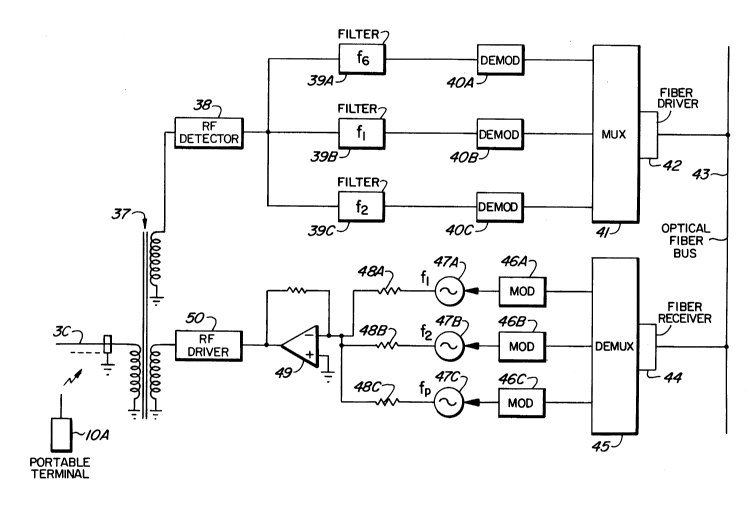
Turning now to Figure 4, a more detailed
block diagram of a base station is shown.
Representative portable terminal lOA transmits in a
wireless manner to representative leaky feeder 3C.
The leaky feeder is connected to a primary
lS winding of transformer 37. A first secondary winding is
connected to an RF detector 38, which is connected to
three bandpass filters 39A, 39B and 39C. Filter 39A is
a bandpass filter for the above-described frequency fb,
filter 39B is a bandpass filter for one of the two
frequencies, e.g. Fl, received from the portable
terminal in the base station, and filter 39C is a
bandpass filter for passing a signal at the second
frequency, e.g. F2.
The filters are connected to corresponding
demodulators 4OA, 4OB and 40C. The outputs of
demodulators 40A, 40B and 40C are connected to inputs of
multiplexer 41, the output of which is connected through
fiber driver 42 to an optical fiber bus 43
(corresponding to network 7 described earlier).
Processor 8 (Figure 1) is connected to the bus 43
through a corresponding fiber interface (not shown).
The base station also is comprised of a
fiber receiver 44, which is connected to the optical
fiber bus 43. The fiber receiver is connected to the
input of demultiplexer 45, the outputs of which are
204312~
-17-
connected to modulators 46A, 46B and 46C . The outputs
of modulators 46A, 46B and 46C are connected to
corresponding carrier signal generators 47A, 47B and
47C, which generate carrier signals at the frequencies
S Fl, F2 and Fp respectively. The outputs of carrier
generators 47A, 47B and 47C are connected via loads 48A,
48B and 48C together to a buffer amplifier 49, the
output of which is connected to the input of RF driver
50. The output of RF driver 50 is connected to a second
secondary of transformer 37.
In operation, signals received from
portable terminal lOA are passed through leaky feeder 3C
and transformer 37 to RF detector 38, where the signal
is detected. The particular carrier frequency Fb or
communication frequency carrier are filtered in filters
39A, 39B or 39C, demodulated in demodulator 40A, 40B or
40C and applied to multiplexer 41. Multiplexer 41
multiplexes the signals received in the different time
slots at the various frequencies received at the various
portable terminals whose signals are received on leaky
feeder 3C, and applies the multiplexed signals via fiber
driver 42 to the bus 43.
Signals received from the processor 8 via
bus 43 pass through fiber receiver 44, are demultiplexed
in demultiplexer 45, designated for the particular
frequencies, and are within the required time slots as a
result of the demultiplexing function. The modulators
46A, 46B and 46C modulate the carrier signals Fp and one
of the communication frequency signals in carrier
generators 47A, 47B and 47C, which are combined, are
passed through buffer amplifier 49 and are amplified by
RF driver 50. The resulting radio frequency signal
passes through transformer 37 to leaky feeder 3C, from
which the signal is transmitted. The portable terminal
to which the signal is addressed, or operating within a
-18- 20 43127
particular time slot reserved for that portable terminal
receives the signal from the processor 8. This can, as
noted above, be either a command signal or a
communication signal from another portable terminal or
S another fixed terminal.
Figure 5 illustrates a portable terminal in
one configuration, that of a pager. The signal is
received via the portable terminal antenna 52, and is
received in RF receiver 53, which contains a tuner at
frequency 23. The resulting signal is demodulated in
demodulator 54, is demultiplexed in demultiplexer 55,
and is detected by controller 56. Controller 56
determines whether the demultiplexed signal is addressed
to its pager. If not, it ignores the signal. If it is
addressed it receives the supervisory or control signal
which follows the address, and if the portable terminal
contains a display 56, displays a message on it and
operates an alerting device such as a vibrator, tone,
etc.
The structure described above as may be
used in a pocket pager is shown in dashed outline.
However if the pager is to provide a speech signal
output, a speech decoder 57 is connected to the
demultiplexer 55. The controller 56 recognizing the
address, thus causes the multiplexer 55 to apply the
following signal to speech decoder 57, which decodes a
received speech signal from digital to analog, applies
it to audio amplifier 58, and passes it to speaker 59.
Figure 6 illustrates the structure used
merely as a location beacon. Controller 56 is connected
to modulator 60 and carrier frequency generator 61,
causing modulation of the carrier 61 to transmit the
identification of the beacon by modulation of the
carrier at predetermined intervals, as described
earlier. The modulated RF signal passes through RF
2043127
- 19-
amplifier 62 to antenna 52 from which it is transmitted
to an adjacent leaky cable.
Figure 7 illustrates a block diagram of a
voice communicating portable terminal. Antenna 52 is
connected to antenna switch 63, an output of which is
connected to RF receiver 53. The output of receiver 53
is connected to demodulator 54, which is connected to
the input of demultiplexer 55. Controller 56 is
connected to demultiplexer 55, and display 56 is
connected to controller 56. The output of demultiplexer
55 is connected to speech decoder 64, the output of
which is connected to audio amplifier 58, which is
connected to speaker 59.
When a signal is received by antenna 52 it
passes through antenna switch 63 into RF receiver 53
which operates as described with reference to Figure 5.
The resulting signal is demodulated in demodulator 54 as
described earlier, is demultiplexed in demultiplexer 55,
and if addressed to the present portable terminal, a
message can be displayed on display 56.
The received signals can cause controller
56 to synchronize with the received signal, to control
the demultiplexer 55 to switch to a particular time slot
and to cause RF receiver 53 to tune to a particular
receive frequency. The received digitized voice
communication signal, if that is the form of
communication used, is passed through the RF receiver
53, is demodulated, demultiplexed, and passed through
speech encoder 64 to audio amplifier 58 from which it is
applied to speaker 59, which voice signal is reproduced
either loudly, or in a handset earpiece.
~ hen a subscriber speaks into microphone
65, its output signal is passed to speech encoder 66,
the digitally encoded output signal being applied to
multiplexer 67. Controller 66 causes the signal to be
-20- 204312~
applied into the previously designated time slot. The
resulting output signal is passed into modulator 68
which modulates a radio frequency signal designated by
controller 56 which had received the voice frequency
S communication supervisory signal from processor 8. The
resulting modulated output signal from RF amplifier 69
is applied to antenna switch 63. When antenna switch 63
receives an RF output signal to be transmitted, it
switches the antenna from receiver 53 to the output of
RF output 69 in order not to overload the input of RF
receiver 53. The resulting signal is transmitted via
antenna 52 to the closest leaky feeders in a micro-cell,
which is controlled by the base station designated by
processor 8.
lS In the above-described manner, a large
number of beacons, paging receivers and portable
telephones can be accommodated within a locally confined
space, by designating micro-cells, reusing frequencies
and time slots associated with non-adjacent parallel
leaky feeders.
Communication may be effected in this
invention using any standard, for example, DECT, CT-2,
CT2 Plus, CT3, or any other mode which will be
understood to operate by a person skilled in the art
understanding this invention. For example, the CT-2 or
CT2 Plus standard can be used with spread spectrum.
Figure 8 illustrates in block diagram
another embodiment of the invention. Each base station
80A, 80B, etc., is connected to multiple splitters 82A,
82B and 83A, 83B, etc. Each splitter is connected to
one or more leaky cables 85 and 86 which are laid in the
ceilings or floors of a building in a grid pattern. The
base stations are connected to a microprocessor via
network 7.
` -21- 2043127
Each base station 80B which feeds a group
of leaky feeders which extend parallel to a Y axis
communicates using a frequency fcy=fl3 to f25, while each
base station 80A which communicates with leaky feeders
85 which are parallel to an X axis, which is orthogonal
to the Y axis, utilizes a frequency fcx=fl to fl2. In
this case it may be seen that full radio frequency
coverage can be provided to an entire floor using either
the base station operating on frequencies fCX or fcy~
Therefore, in some installations it may be desirable to
utilize only leaky feeders 85 or leaky feeders 86.
It may be seen that no additional floor
area is covered using both base station 80A and base
station 80B, and furthermore, since the signal
transmitted by either is split in one of the splitters
and is applied to all of the associated leaky feeders,
the entire region covered by either set of parallel
leaky feeders or both sets of orthogonal leaky feeders,
and can be defined as a mini-cell. Plural mini-cells
located over the floor area of a building can provide
the location function described above. Alternatively,
one floor of a building covered by a mini-cell, used in
concert with plural similar structures, one covering
each floor of a high rise building provides a location
function in the building in a manner described above.
For the structures described with reference
to Figure 8 which forms a single mini-cell, the reason
that orthogonal leaky feeders connected to separate base
stations 80A and 80B are used, is to increase the number
of frequencies, and thus the number of portable
terminals that can be accommodated within a single mini-
cell. It also allows redundancy.
Clearly more than two orthogonal groups of
leaky feeder lines can be utilized, in order to
3s accommodate more RF channels, for base stations having a
-22- 2043127
limited number of frequencies. The leaky feeders need
not be parallel to X and Y orthogonal axes; another
group of leaky feeders or a substitute group of leaky
feeders may be used which are, e.g. diagonal to the ones
S shown in Figure 8.
Figure 9 illustrates the case referred to
above, of parallel leaky feeders 85 whose effective
radio frequency field covers an area of utilization
without requiring leaky feeders which are parallel to an
axis orthogonal thereto. The base stations 90A, 90B and
90C can each operate using communication frequencies
F1-Fl2. Alternatively, by using the single base station
and multiple splitters configuration described with
reference to Figure 8, plural base stations can be
lS dispensed with.
Figure 10 is similar to Figure 9 except
that there is only one leaky feeder 85 extending along
the X axis, and only one leaky feeder 86 extending along
the Y axis, each connected to a corresponding base
station 92A and 92B. The two cables define a mini-cell
as described above. The base stations 92A and 92B can
operate communication frequencies which are either
identical, as described with reference to Figures 8 and
9, or are different as described with reference to
Figure 1.
Indeed, by utilizing only one cable per
building storey, e.g. either 85 or 86, each defining a
mini-cell, a multiple storey building can be covered.
In this case the portable terminal location scheme
described with reference to Figures 1-8 can be utilized,
with the network 7 running up the building in the manner
of a backbone. The mini-cells are thus stacked
vertically, rather than being dispersed horizontally and
stacked vertically.
-23- 20~31~7
Since the CT-2 standard limits each base
station to a maximum of twelve radio frequency channels,
overlaying leaky feed as described herein, allows more
radio frequency channels per unit area to be used, and
thus more portable terminals to be used per unit area.
Further, by the use of spread spectrum, the maximum
radio frequency radio intensity at a particular
frequency is minimized, thus allowing minimal
interference with other services, and confidentiality of
communication.
A person skilled in the art understanding
this invention may now conceive of variations or other
embodiments using the principles of the invention
described herein. All are considered to be within the
scope of the invention as defined in the claims appended
hereto.