Note: Descriptions are shown in the official language in which they were submitted.
2043302
This invention relates to a system for tuning pianos
and other musical string instruments where accurate pitch
(or frequency) is dependent on the accurate adjustment of
string tension. In such instruments precise tuning is
essential to producing pleasurable sounds.
Devices known as "piano tuning machines" have been
previously developed, however, contrary to what their name
implies, these devices are merely pitch indicators and do
not actually physically tune the string. Thus they only
provide the piano tuner with an indication of whether the
string is sharp or flat. The piano tuner must then
manually adjust the string tension to achieve the correct
pitch.
Some of these devices illuminate the vibrating string
with a stroboscopic light flashing at the correct
frequency. When correctly tuned, the string will appear
to stand still or move very slowly. Other devices have
microphones and use galvanometer needles and indicator
lights to indicate flat or sharp or correct pitch. The
main function such devices serve is to reduce or eliminate
the need for a well-trained ear, but they do not assist
with the mechanical labour-intensive tasks associated with
adjusting the string tension.
The idea of having the tension adjusted by a machine,
instead of by hand, is not itself new. In U.S. Pat.
#4,088,052 Hedrick proposes such a system. The idea is
also presented in U.S. Pat. #'s 4,196,652 and 4,327,623.
Normally, a piano string is made to vibrate by
striking it with a felt hammer. Energy is added to the
string at the moment of impact, and the string then
vibrates on its own. Due to the stiffness of the string,
there are harmonics with subtle frequency offsets which
can make it difficult to accurately determine the
prevailing pitch or frequency of the string. This problem A
2043302
is particularly acute for notes in the lower octaves of
the piano keyboard. Mochida et al (U.S. Pat. # 4,327,623)
have attempted to address this problem with a complex
signal processor which they call a "Fundamental Wave
Extracting Circuit".
In the upper octaves of a piano the harmonics are not
a problem, however, in these higher octaves, striking the
string results in a vibration of too short a duration to
permit accurate pitch adjustment. Hedrick attempts to
address this problem by having his system operate in
intermittent time intervals in order to give the operator
a chance to repeatedly strike the same note such that the
discontinuity in the vibration, caused by each impact does
not interfere with the tuning control system.
Striking the string causes other problems as well.
Since no energy is added to the string during the
vibration, the amplitude of the string vibration
diminishes with time. During this time, the actual pitch
changes slightly due to non-linearities in the string
which cause the natural frequency to be slightly dependent
on amplitude. Also, the actual impact on the string when
it is struck can cause it to shift in its mounting in such
a way that its natural frequency is changed by the impact.
These two factors make tuning by striking the string more
difficult and limit the accuracy which can be achieved.
When tuning a piano manually, either by ear or with a
pitch indicator, the piano tuner can only tune one string
at a time. Since the majority of the notes in a typical
piano have three strings each, the tuner must use rubber
wedges called "mutes" to prevent adjacent strings from
interfering. This can significantly add to the length of
time required to tune a piano. A device described by Van
Der Woerd in U.S. Pat. # 3,675,529, represents an attempt
to address this problem. This device incorporates a
-3- 2043302
sensor into an assembly with dampers which prevents nearby
strings of the same pitch from vibrating and thereby
interfering with the string being tuned. The application
of this device is limited because of its inability to
accommodate variations in string spacing.
Furthermore, the strong static friction or "stiction"
in the tuning pins, which is needed to prevent the piano
strings from going out of tune prematurely, makes it
difficult to adjust the string tension in a precisely
controlled manner.
It is an object of the present invention to provide a
piano tuning system which overcomes the above
disadvantages. The problems of interfering harmonics and
insufficient duration of vibration are eliminated by
controlling the vibration of the string through
electromagnetic forces. Thus, vibrational energy is added
to the string in a controlled manner while the string is
vibrating. In this way the string can be induced to
vibrate at its natural fundamental frequency without the
presence of interfering harmonics, and for as long as is
needed to accomplish the necessary tension adjustments.
The present invention achieves this control by the
use of sensors to sense the instantaneous position of the
string, an electromagnet capable of transmitting
controlled forces to the string, and electronic circuitry
which couples the sensor and the electromagnet in a
feedback loop with the correct phase angle for adding
energy to the string at its natural frequency.
Another object of the present invention is to provide
a self-aligning probe with a sensor and dampers in which
there is allowance for variations in spacing between the
strings. The present invention uses dampers not only to
damp out other strings but also to gauge string spacing.
Z043302
A mechanical arrangement converts this measurement into a
position offset which permits correct alignment between
the sensor and the string being tuned.
It is yet another object of the present invention to
overcome static friction or stiction in the tuning pin, by
designing a large measure of stiffness into the mechanism
which rotates the pin. Even with the best of design, the
stiffness can never be infinite and therefore there will
always be a minimum rotational speed, below which static
friction will prevent smooth rotation of the pin. For
this reason, it is important that the entire system be
able to respond quickly to small changes in pitch.
Many schemes for pitch determination have been
devised for the devices which give a visual indication of
pitch. In these devices, the speed of response of the
indicator is not as important due to the reaction time of
the user. In an automated system, however, the speed of
response of the pitch determining circuit has a profound
effect on the accuracy achieved. Thus, the present
invention incorporates a pitch determining circuit which
possesses a high speed of response while maintaining a
large measure of immunity to noise. This is achieved by
measuring the phase between the signal and reference
waveforms and monitoring its change.
In some pianos, particularly older ones, lack of
stiffness in the pin mounting block can cause a hysteresis
which cannot be eliminated by stiffness in the tension
adjusting mechanism. Such hysteresis is compensated for
by tuning to a slightly higher frequency so that when the
torque on the tuning pin is released, the tension on the
string rotates the pin until the correct frequency is
achieved.
2043302
Brief Description of the Drawings
In drawings which illustrate by way of example only a
preferred embodiment of the invention,
Fig. 1 is a pictorial block diagram showing the main
components of the piano tuning system;
Fig. 2 is a front elevational view of the standard
probe;
Fig. 3 is a cross-sectional view along line 3-3 of
Fig. 2;
Fig. 4 is a top plan view of the probe of Fig. 2;
Fig. 5 shows a detail of the coil arrangement of the
sensor;
Figs. 6, 7, 8 and 10 show the probe mounted on
strings;
Fig. 9 is a section along line 9-9 of Fig. 8;
Fig. 11 is a section along line 11-11 of Fig. 10;
Fig. 12 is a side elevation of a further embodiment
of an electromagnet;
Fig. 13 is a sectional view along line 13-13 of Fig.
12;
Fig. 14 is a front elevation of the preferred
embodiment of a low frequency probe;
Fig. 15 is a side elevation of the probe of Fig. 14;
20 43302
--6--
Fig. 16 is a top plan view of the probe of Fig. 14;
Figs. 17 and 18 are top plan views of the probe of
Fig. 14 mounted on strings;
Fig. 19 is a schematic diagram of the frequency
reference shown in Fig. 1;
Fig. 20 is a set of electronic circuit equivalents
for circuit blocks illustrated in Figs. 21, 22, 23 and 24;
Fig. 21 is a schematic diagram of the signal
processor shown in Fig. 1;
Fig. 22 is a schematic diagram of the frequency
comparator shown in Fig. 1;
Fig. 23 is a schematic diagram of the motor
controller shown in Fig. 1;
Fig. 24 is an alternative embodiment of the frequency
comparator illustrated in Fig. 22;
Fig. 25 shows the controller on a piano keyboard; and
Fig. 26 is a section along line 26-26 of Fig. 25.
Detailed Description of the Invention
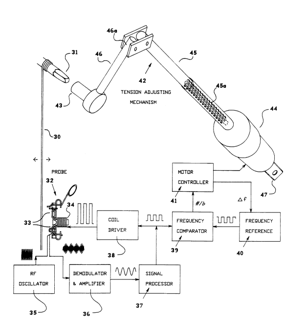
Referring to Figs. 1, 2 and 3 there is shown a single
piano string 30, the tension of which can be adjusted by
rotating the pin 31. A probe 32, comprising a body 53,
clamps 48, sensor coils 33, an electromagnet 34, retaining
pins 50 and dampers 51, is clamped onto one or two
adjacent strings (as in Figs. 7, 8) such that the sensor
coils 33 and the electromagnet 34 are aligned with the
string 30.
~7~ 20 43302
As will be described in greater detail below, the RF
tradio frequency) oscillator 35 provides the sensor coils
with an excitation signal. The signal picked up by the
sensor from the string is a low level RF carrier which is
amplitude modulated at the string vibration frequency.
This signal is demodulated and amplified by the
demodulator and amplifier 36 to produce an audio signal.
The signal processor 37 converts the signal into a square
wave with a 50% duty cycle, and with the correct phase
shift. The coil driver 38 amplifies the signal processor
output to drive the electromagnet 34. The electromagnet
34 transmits a time varying mechanical force to the string
30, thereby closing the feedback loop and causing the
string 30 to vibrate continuously at its natural
frequency. The natural frequency can be either the
fundamental or a harmonic depending on the amount of phase
shift used, however, the fundamental is preferred.
The square wave signal from the signal processor 37
is also fed into the frequency comparator 39 which
compares the frequency of said signal with the frequency
of the frequency reference 40. The output of the
frequency comparator 39, which indicates the frequency (or
pitch) error is connected to a control input on the motor
controller 41. The motor controller 41 supplies
controlled electric power to the DC gear-motor 44 which in
turn drives the tension adjusting mechanism 42.
In a preferred embodiment the gear-motor 44 turns a
leadscrew 45a which is enclosed in the telescoping tuning
arm 45. The tuning arm 45 applies force to the end 46a of
the torque arm 46 causing it to apply torque to the tuning
pin 31, via the mating socket 43, thereby causing the pin
31 to rotate. The reaction force is taken by the bracket
47 which is secured to any suitable immobile part on the
piano frame, such as the movement mounting studs.
-8- 2043302
When the correct string frequency is reached, this is
detected by the frequency comparator 39 which then signals
the motor controller 41 to momentarily reverse the motor
44 to release the mechanism for removal. Preferably the
socket 43 is ratchet actuated to be driven only in the
clockwise direction, to tighten the pin 31. Thus
momentary reversal of the socket 43 will not itself
reverse the rotation of the pin 31.
If the string goes flat when the torque is released,
the tuning process is repeated but the controller 41
causes the string 30 to be tightened to a slightly higher
pitch before releasing the mechanism torque again. This
process is repeated if necessary until the string is in
tune, i.e. the natural frequency of the string equals the
reference frequency.
Referring now to Figs. 2 to 4, in addition to the
sensors 33 and electromagnet 34 whose tip is numbered 52,
the probe has two clamps 48 which by manual rotation,
clamp the string against two pins 50, and two dampers 51
which are pivotally mounted on the probe body 53. The
clamps 48 are operated by manually applying force to
handles 49. A small amount of flexibility inherent in the
upper portion of the probe body 53 and the tips of the
clamps 48 enables the clamps to accommodate a range of
string thicknesses.
Referring now to Fig. 5, each sensor 33 consists of
an outer transmit coil 54 which is preferably mounted at
right angles to an inner receive coil 55, so that there is
no direct electromagnetic coupling between them. The
presence of a metallic string, however, causes the
electromagnetic field to be distorted in such a manner
that some of the signal from the transmit coil 54 is
picked up by the receive coil 55. The closer the string,
the stronger the signal. Some interference can also be
2043302
picked up from the electromagnet 34, however, this problem
is minimized by using two sensors 33 mounted the same
distance from the electromagnet 34, as shown in Figures 2
and 3, and connecting the receive coils 55 in such a
manner that the interference is cancelled out. The sensor
coils are preferably mounted each at a 45 angle to the
probe, thus maximizing exposure to the string being tuned.
Referring now to Fig. 6, the clamps 48 are operated
by rotation from the open position 48a to the closed
position 48b. Referring to Fig. 7, if the middle string
56 in a group of three is to be tuned, the clamps 48 are
rotated until they grip the two outer strings 57 by
forcing same against the pins 50. This will have a
damping effect on the outer strings 57, reinforced by
resilient dampers 51 which also help to ensure that the
sensors 33 and the electromagnet tip 52 are properly
aligned with the string 56.
Referring to Figs. 8 and 9, if an outer string 57 is
to be tuned, then only one clamp 48b and one damper 51 is
used. The clamp 48b is rotated until it grips the middle
string 56 by forcing it against the pin 50. In such a
case, the result of the forces on the string 56 between
the clamp 48b and the pin 50 is a torque which tends to
push the lower portion of the probe away from the middle
string 56. The lower portion of the probe is free to move
away from the middle string 56 until the damper 51 comes
in contact with the other outer string 57a, causing it to
be damped out, and also causing the sensors 33 and the
electromagnet tip 52 to be correctly aligned with the
string being tuned, in this case the outer string 57.
Referring to Figs. 10 and 11, if the strings diverge
downwardly, as is the case in many pianos, then the
pivotally mounted damper 51 is rotated to a sharper
horizontal angle before contacting its outer string.
-10- 2043302
Thus, the lower sensor 33 will be positioned farther away
from the middle string 56, so that as long as the strings
are symmetrically spaced, the sensor 33 will be correctly
aligned with the string being tuned.
In many upright pianos, the strings for the lower
octaves form a layer which overlays some of the strings
for the upper octaves. Consequently, only a short length
at the end of some of the strings may be accessible to the
probe 32. This presents difficulties because the
vibration of a string can be difficult to control if it is
induced at the end instead of the middle of the string.
This problem can be eliminated by the use of a further
embodiment of an electromagnet 58, illustrated in Figures
12 and 13. This electromagnet 58 clamps onto a lower
pitched string 59 using clamps 60, and has an
electromagnet tip 61 which traverses the overlaying layer
of lower pitched strings, permitting access to the middle
sections of the upper octave strings 62.
In most pianos, the strings in the lower range
consist of a thin steel core onto which additional wire
has been wound in the shape of a helix. The diameters of
these strings can be as large as 1/4 of an inch. The
standard probe illustrated in Figs. 2 to 4 could
adequately sense their vibration, but would be unable to
clamp onto them. Figs. 14 to 16 illustrate a probe 63
designed for low frequency strings which can accommodate
their larger diameters. The probe 63 is clamped onto
adjacent strings by trapezoidal clamps 64 and the
alignment of the sensors 33 and the electromagnet tip 65
is achieved by the guiding plates or ridges 66. The
clamping force is supplied by the spring 67. The
electromagnet coil 68 is of a larger size because of the
need for increased power output, which is satisfactory due
to the decreased need for frequency response.
-11- 2043302
In the lower octaves string spacing varies because
some lower notes have two strings each while others have
only one string. The probe 63 adapts to the smaller
spacing by clamping around the two strings on either side
of the string being tuned, as illustrated in Fig. 17. The
probe 63 adapts to the larger spacing by clamping in
between the two strings on either side of said string, as
illustrated in Fig. 18.
Referring now to Fig. 19, a quartz crystal 69 is made
to oscillate at a known frequency by a CMOS (complementary
metal oxide semiconductor) inverter 70, which produces a
highly stable and accurate high frequency square wave 71.
Most of the pulses in the square wave are fed into the
input of the "divide by N" counter 72 which divides this
frequency by the number "N" which is supplied by the read
only memory 73. The number "N" supplied by the read only
memory 73 depends on which semi-tone has been selected by
the semi-tone selector switch 74. The output of the
divide by N counter is fed into the input of a binary
counter 75 which produces frequencies corresponding to the
selected semi-tone in each octave. One of these
frequencies is selected by the octave selector switch 76.
The semi-tone selector switch 74 and the octave selector
switch 76 together enable the operator to select the
frequency of any note on a piano keyboard.
To improve the accuracy of the circuit, two logic NOR
gates 77 and 78 are used to make the divide by N counter
72 serve as a divide by N+1 counter whenever the output 79
of the digital comparator 80 is low. In this mode, any
transition from high to low on the output 81 of the divide
by N counter will cause a pulse to be generated at one
input 83 of the logic NOR gate 77. This causes the logic
NOR gate 77 to block one pulse coming from the quartz
crystal oscillator for every "N" pulses counted by the
divide by N counter. Since the divide by N counter 72
-12- 20 4330 2
only counts unblocked pulses, the oscillator must produce
"N+l" pulses for every count going into the binary counter
75 as long as the output 79 of the digital comparator 80
is low. If the output is high, then no pulses are blocked
and the oscillator only needs to produce "N" pulses for
every pulse going into the counter 72.
Digital outputs from the read only memory 73
determine the ratio of "N" counting to "N+l" counting.
This ratio remains the same regardless of the order in
which outputs from the binary counter 75 are connected to
inputs on the digital comparator 80, however, minimum
phase error accumulation is achieved when the output 79
frequency of the digital comparator 80 is maximum. To
minimize the phase error accumulation in the reference
frequency signal 82, the outputs of the binary counter 75
are connected to the inputs of the digital comparator 80
in reverse order. (MSB to LSB, 2nd MSB to 2nd LSB,.....
LSB to MSB). This results in the frequency reference
being so accurate that its accuracy is limited primarily
by the accuracy of the quartz crystal oscillator. If
necessary, this highly accurate reference frequency signal
82 can be offset to slightly different frequency values by
the "/\f" (frequency differential) inputs 84. The amount
of frequency offset depends on what is programmed into the
read only memory 73.
Referring to Fig. 20, a circuit equivalent is given
for each of seven circuit blocks used in succeeding
figures. In the frequency to voltage converter 85, the
input is connected to a charge pump 86 which feeds the
negative input of an operational amplifier. The output is
smoothed into an analog voltage by a resistor 86a and
capacitor 86b connected in feedback. As long as the input
voltage is constant, the output voltage will be a negative
going voltage proportional to input frequency.
-13- 2043302
The integrator 87 is a standard circuit except that a
transistor 88 has been added to give it a reset input.
The sample and hold amplifier 89 uses a transmission
gate 90 to sample the input. When the input to the gate
S so is high, the output voltage equals the input voltage.
Otherwise, the last input voltage value is stored in the
capacitor and the output remains locked to this value.
The Schmitt trigger 91 is a standard circuit, and
will be well known to those skilled in the art.
The window comparator 92 combines two comparators
with a resistive divider and a logic OR gate so that the
output goes high whenever the input voltage value is
outside a voltage range which is defined by the resistive
divider.
Flip-flop 93 is a standard circuit and will be well
known to those skilled in the art.
The data selector 94 uses logic gates to select one
of two data inputs, depending upon whether the control
input is high or low. If said control input is low, then
the upper data input is selected. If said input is high,
then the lower data input is selected. The logic level of
the selected data input is transferred to the output.
A preferred embodiment of signal processor 37 is
illustrated in Fig. 21. The frequency to voltage
converter 85 converts the reference frequency signal 82
into an analog voltage which controls the speed of the
integrators 87a and 87b to match the frequency of the
reference frequency signal 82. The demodulated and
amplified probe signal 95 is fed into the "S" input of the
flip-flop 93a. At each positive zero crossing of this
signal, the "Q-bar" signal goes low and the integrator 87a
-14- 2043302
starts. The voltage output of the integrator 87a rises
until the comparator 96 resets flip-flop 93a, causing the
integrator 87a to be reset. The resulting wave form is a
sawtooth wave with spaces between the teeth. These spaces
allow for frequency differences between the probe signal
95 and the reference frequency signal 82. This sawtooth
wave is fed into comparator 97 which sets flip-flop 93b
when the voltage of the sawtooth exceeds a certain level,
causing integrator 87b to start approximately 90 after
each positive zero crossing of probe signal 95. The
comparator 98 resets flip-flop 93b after an additional
180. The integrator 87c adjusts the threshold of the
comparator 98 to maintain a 50% output duty cycle in spite
of any circuit inaccuracies which may exist. The "Q"
output of flip-flop 93b is therefore a squared version of
the probe signal 95 but delayed by approximately 90.
This "Q" output is inverted by the inverter 99 to produce
the processed probe signal 100 which is advanced by
approximately 90 ahead of the probe signal 95. The
resistor 101 is used to further advance the phase of the
processed probe signal 95 at higher frequencies in order
to compensate for phase delays in the probe.
A preferred embodiment of the frequency comparator is
illustrated in Fig. 22. A frequency to voltage converter
85 is coupled to an integrator 87 with its reset input
activated with each rising edge on the reference frequency
signal 82. The output 102 of the integrator 87 is a
sawtooth wave of a constant amplitude having the same
frequency as the frequency reference signal 82. The RC
network 103 causes any positive transition on the
processed probe signal 100 to in turn cause the sample and
hold amplifier 89a to sample the waveform 102 such that
the output 104 of the amplifier 89a is a voltage
proportional to the phase difference between the reference
frequency signal 82 and the processed probe signal 100.
This output 104 is fed into a second sample and hold
-15- 2 0 4 3 3 0 2
amplifier 89b, the output and input of which are connected
to a differential amplifier 105. The amplifier 105
amplifies the voltage difference between said input and
output. If the voltage difference is greater than a
preset value, then the amplifier 105 first triggers the
Schmitt trigger 91 and then triggers the window comparator
92a. The window comparator 92a then causes the sample and
hold amplifier 89b to set its output equal to its input,
causing the output of the differential amplifier 105 to
return to its midpoint.
If the phase signal 104 changes again, by a
sufficient amount, this process is repeated. The output
of the Schmitt trigger 91 indicates the direction of the
phase change and therefore indicates whether the processed
probe signal 100 frequency is higher or lower than the
frequency of the reference frequency signal 82, with the
exception that this part of the circuit becomes
momentarily unstable when the sample and hold amplifier
89a tries to sample the falling edge of the sawtooth wave
102. This problem is eliminated by having a second
identical circuit portion which operates 180 out of phase
of the first circuit portion, using the inverted signal
output of the inverter 106. While one circuit portion is
unstable, the other can be selected to give the required
indication. If the voltage on the signal 102 is close to
a falling edge (either side), the window comparator 92b
activates the logic AND gates 107. Any pulses coming from
the RC networks 103 and 108 will then trigger flip-flop
93, causing the data selector to select the circuit
portion opposite to the one which produced the pulse. In
this way, the data selector 94 selects the signal from the
stable circuit portion so that its output, and also the
frequency comparator output 109 gives a true indication at
all times as to whether the processed probe signal 100
frequency is high or low (sharp or flat, #/b). The
voltage window of the window comparator 92a has the effect
-16-
2043302
of giving the circuit a phase deadband or hysteresis which
makes it less sensitive to noise. Having the deadband
with respect to phase instead of frequency offset is
advantageous. Firstly, a phase deadband does not put a
limit on the smallest frequency difference that can be
detected, but only increases the length of time required
to detect it in inverse proportion to the amount of the
differential. Secondly, the length of time required for
detection is smaller for larger frequency differences for
which a high speed of response is more important, so that
both high accuracy and a high speed of response are
maintained as needed.
A preferred embodiment of the motor controller is
illustrated in Fig. 23. Power to the motor 111 is
controlled by a bridge arrangement of power transistors
112. If the right input 113 goes high, which happens if
the "tighten" switch 114 is closed momentarily, the motor
111 is made to rotate clockwise (forward). If the left
input 115 goes high, which happens if the "loosen" switch
116 is closed momentarily, the motor 111 is made to rotate
counterclockwise (reverse). Initially, before the circuit
is activated, a charge is maintained on the capacitor 117
by the output of the logic NOR gate 118 via a diode 119,
and a resistor 120. If the "tune" switch 121 is closed
while the #/b (sharp/flat) input 122 (connected to the
frequency comparator output 109, Fig. 22) is low
(indicating flat), it causes the output of the logic NOR
gate 118 to go low, and the capacitor 117 is allowed to
discharge through the resistors 120 and 123. This causes
the other input of the logic NOR gate 124 to go low
causing the output of gate 124 to go high thereby enabling
the tuning cycle to continue after the "tune" switch is no
longer closed. The diode 125 conducts this signal to the
right input 113 of the power bridge causing the motor 111
to rotate in the forward direction. If the #/b
(sharp/flat) input 122 goes high momentarily due to a
-17- 2043302
noise spike, the output of the logic NOR gate 124 will
immediately go low, causing the motor to decelerate. The
output of the logic NOR gate 118 will also go high
momentarily, and the capacitor 117 will start to charge
via the diode 119 and the resistor 120. However, the
noise spike will not last long enough to charge the
capacitor 117, so that when the #/b (sharp/flat) input 122
goes low again, the output of the logic NOR gate 124 will
again go high, and the motor will continue rotating
forward and tightening the string. If the #/b
(sharp/flat) input 122 goes high and stays high, then the
output of the logic NOR gate 124 goes low and the motor
111 stops rotating. The capacitor 126 causes the input of
the inverter 127 to go low and stay low momentarily as
lS determined by the resistor 128. The diode 129 conducts
the output of said inverter to the left input of the power
bridge, causing the motor 111 to reverse momentarily.
This releases the torque and allows the tension adjusting
mechanism to be moved to another tuning pin.
If the note goes flat again while the torque is being
released (due to hysteresis), then the resistor 130 and
the diode 131 will cause the capacitor 117 to be
discharged, thereby causing the tuning cycle to repeat
itself with the exception that the binary counter 132 has
been advanced to the next ~ f value. The binary counter
132 is set to zero by the "clear" input whenever the
"tune" switch 121 is closed. It advances to the next
value when the #/b (sharp/flat) input 122 goes high and
stays high long enough to charge the capacitor 133 through
the resistor 134. This prevents the counter from being
triggered by noise.
The Schmitt trigger 135 ensures that the counter will
get a proper rising edge. The logic AND gates 136
activate the /~f outputs 137 while the string is being
tightened and deactivate them while the torque is being
-18- 2043302
released. If the #/b (sharp/flat) input 122 stays high
for the duration determined by the capacitor 126 and the
resistor 128, then after the output of the inverter 127
goes low, the output of the inverter 138 goes high, and
through the diode 139 prevents the capacitor 117 from
being discharged through the diode 131. The motor then
stops turning.
The sequence of operation is as follows: With the
bracket 47 of the tuning arm 45 secured to the piano
frame, the operator secures the socket 43 over the tuning
pin of the string to be tuned and places the probe 32, or
63, as previously described, over the string to be tuned.
The operator must ensure that the frequency selected by
the combination of the octave and semi-tone selector
switches corresponds to the frequency of the string being
tuned. The momentary "tune" switch 121 is closed, the
binary counter resets to zero, and the motor turns in the
forward direction to tighten the string until the #/b
(sharp/flat) input goes high. If said input goes high
only momentarily due to a noise spike the motor
momentarily decelerates, but otherwise the noise spike is
ignored. If said input goes high for a longer duration,
the binary counter is advanced and the motor is put in
reverse. If said input goes low while the torque is being
released (motor in reverse), then the tuning cycle resumes
with the binary counter taking the next larger count.
Tuning stops if the #/b (sharp/flat) signal 122 stays high
for the full duration of the motor reverse motion. If
desired, the frequency modifying anti-hysteresis feature
can be disabled by disconnecting the diode 131, in which
case the controller will do one forward/reverse cycle in
which the forward motion is terminated by a low to high
transition on the #/b input. The operator then selects
the pitch of the next string to be tuned, moves the socket
43 and probe 32, or 63 to the next string, and repeats the
operation.
2043302
Referring now to Figs. 25 and 26, one of the
difficulties an operator may experience, if the piano is
very badly out of tune, is uncertainty about whether the
controller 143 is set to the correct note. This problem
is addressed by having twelve indicator lights 140 on the
controller, one for each semi-tone of an octave,
positioned above their respective keys on the keyboard.
The bottom surface 144 of the controller 143 itself may be
provided with slots 141 cut into it of a size and spacing
to match the black keys 142 on the piano keyboard. During
the tuning session, the controller 143 rests on top of the
piano keyboard and the slot pattern in the bottom of the
controller 143 ensures that for each octave, the
controller 143 can be located on the keyboard in only one
position, being the position in which the semi-tone
indicator lights are individually positioned directly
above or adjacent to their corresponding keys (on the
keyboard). This also ensures that on any piano,
regardless of its design, there will always be a
convenient place to rest the controller during the tuning
operation.
Some alternative embodiments of the present invention
will now be briefly described. Instead of using
electromagnetic RF coils, one could use a single passive
coil which responds to the changes in the magnetic field
which occur when the string vibrates near a permanent
magnet or other source of magnetic flux. Instead of using
a coil, one could use a Hall effect sensor. Another
option would be to make the electromagnet itself into a
sensor since the string vibration induces a voltage on its
terminals. Some means would be required to separate this
signal from the excitation voltage. Instead of using
electromagnetic methods, one could use electrostatics.
The string could be charged with a DC voltage so that its
vibration induces a voltage in a nearby conductive
surface. An optical detector such as a photodiode or
-20- 2043302
phototransistor can also pick up vibration if the string
surface is illuminated by optical radiation. A laser
diode of the type used in compact disc players could
provide illumination for very sensitive vibration sensing
provided that it is well focused. Focusing and
positioning could be achieved using the same moving coil
arrangement found in these disc players. Finally, a
microphone can be used, however, it must have the required
frequency response and must be properly positioned.
An alternative to the clamp and damper arrangement,
would be to replace the clamps with dampers so that the
probe has four dampers. The dampers could be spring
loaded and have notches to help them maintain their grip
on the strings.
A probe with one side missing, could be useful for
reaching strings in hard-to-get-to places such as next to
a support beam.
It may also be possible to fit the probe onto an
automated device which, by sequentially gripping the
strings, is able to automatically index the probe from one
string to the next. Indexing could also be done relative
to a temporarily mounted track. An alternative to this
would be to construct a multi-element array of sensors and
electromagnets, one for each string. Damping of adjacent
strings could be accomplished electronically, by feeding
the electromagnets signals which are the exact opposite
phase of the signals that would be required to build up
the vibration. Damping could also be accomplished by the
use of solenoid actuated dampers.
Many of the analog circuit functions could be
achieved with digital circuitry. For the phase shifting
circuit in the signal processor, an oscillator and a
counter could be used to generate a time delay according
-21- 2043302
to information stored in read only memory. Another
approach would be to use a phase-lock loop. The frequency
comparator can be made to work with digital circuitry as
shown in Fig. 24. Instead of a sawtooth wave, the digital
equivalent is used, this being the output of a binary
counter. Data latches can then be used instead of sample
and hold circuits, while the basic functional principle
remains the same. If the analog version is used, however,
a simple way to achieve the ~ f offsets is to feed
controlled currents into the capacitors of the second
stage sample and hold amplifiers.
There are different strategies that can be used when
offsetting the reference frequency in order to compensate
for hysteresis. Before each successive tuning cycle, the
reference frequency can be increased by the same
percentage increment. Alternatively, the amount by which
the note goes flat due to hysteresis can be measured, and
this value used to determine the next frequency offset.
Another way to address the problem of hysteresis is
to use impact torque for adjusting the tension. A smaller
amount of impact torque could be added to static torque in
order to reduce the shock waves in the piano frame that
impact torque tends to produce.
In the described embodiment, there are no warning
signals given to the operator who is therefore required to
maintain a certain level of alertness. A warning could be
added to warn the operator if changing the tension doesn't
change the natural frequency. This could be coupled to an
automatic shutdown circuit if the operator doesn't
respond. This could address the problem which can arise
if the operator inadvertently puts the tension adjusting
mechanism onto a pin which does not correspond to the
string which has the probe. Other warnings for problems
such as excessive torque could also be added.
-22- 2043302
Another approach to handling the analog and the
digital circuit functions is to use a microcomputer, and
program in the functions with software, in a manner which
will be obvious to someone skilled in the art.
An alternative to inducing vibration at the natural
frequency of the string and comparing this to a reference
frequency, is to induce vibration at the desired frequency
and compare the phase shift of the response to what it
should be if the string is in tune. In this case, the
frequency error of the controlled vibration would be zero,
regardless of the natural frequency error of the string,
the natural frequency error being the difference between
the desired natural frequency, and the natural frequency
at which the string would vibrate if it was vibrating on
its own. Therefore, the natural frequency error is not
measured directly in this case, but is instead determined
using information derived from the phase shift signal.
The advantage of this approach is that the electronic
circuitry can be greatly simplified. The signal processor
is no longer needed as the signal from the frequency
reference can be fed directly into the electromagnet coil
driver. The frequency comparator is also no longer needed
and can be replaced with a simple circuit for measuring
phase and comparing it to the desired value. This could
for example be in the form of a timing circuit which
measures the time interval between the positive zero
crossings of the electromagnet coil driver input signal
and the demodulated sensor output signal, and compares
this value to a normal value stored in read only memory.
If the string is flat, then the phase of the demodulated
sensor signal will lag behind the normal value, while if
it is sharp, it will lead or be ahead of the normal value.
In this way, the timing circuit can have a sharp/flat
output equivalent to that of the frequency comparator
which it replaces. One disadvantage is that it is not as
accurate, and while this could be addressed by a means of
-23- 2043302
averaging over a number of cycles, such a solution would
tend to detract from the simplicity of this approach.
Another disadvantage is that in its simplest form, it
would not work very well on pianos (or other string
instruments) which are very badly out of tune, because the
string will only respond to vibrational energy close to or
at its natural frequency (or frequencies). This problem
could be addressed by offsetting the reference frequency
(e.g. with ~ f inputs) initially and then moving it closer
to the correct frequency as the natural frequency of the
string approaches the correct value. The reference
frequency could then be set to the correct value (or some
other chosen value) once the natural frequency is within
range. Implementing this kind of solution would also tend
to detract from the simplicity of this approach.
The described embodiment does not have a provision
for loosening the strings if they are sharp, as this
simplifies the design of the tension adjusting mechanism,
however, this feature could be added.
At the sacrifice of some portability, the electric
gear motor could be replaced with a high speed direct
drive electric motor. This would require a much larger
power supply, but would speed up the tuning process. A
provision would also be needed for slowing the motor down
as the frequency approaches the correct value in order to
prevent overshoot.
Finally, a robotic system could be used to
sequentially position the tension adjusting mechanism onto
all of the tuning pins so that an operator is not needed
while the tuning is in progress. This when combined with
the previously mentioned multi-element array, or probe
indexing, and with electronic or other means of damping,
could provide an automatic tuning system that is well
suited to a production environment. Such a robotic system
-24- 2043302
could also be part of a module containing the above, and
which mounts into the piano (or other instrument) in place
of the movement. Such a module could be made portable,
however, the greatest portability would be achieved by the
embodiment described in detail above.