Note: Descriptions are shown in the official language in which they were submitted.
Z0433;~9
TITLE OF THE INVENTION
A REMOTE CONTROL SYSTEM
FOR CONTROLLING A TELEVISION RECEIVER
BACKGROUND OF THE INVENTION
1. Field of The Invention
This invention relates to a remote control system
for controlling a television receiver or the like.
2. Description of The Prior Art
In recent years, there has been a trend toward
large television receivers. Moreover, projection
television receivers each of which meets a demand for a
very large screen and has equipment provided on the ceiling
of a room for projecting an image on a screen mounted on a
wall thereof instead of a cathode ray tube (CRT) have been
coming into wide use.
When using the projection television receivers, it
is necessary for showing a motion picture to shade a room
similarly as in case of showing a picture at a movie
theater (i.e., a cinema house). However, when a room is
darkened, characters printed on a remote control system
which are necessary for manipulating the remote control
system becomes hard to read and as a result the remote
control system becomes difficult to manipulate.
As a countermeasure for this, a system in which an
illuminator is incorporated into a conventional remote
_ -2- 20433~9
control device is employed. However, when using this
system, it is necessary for a viewer to alternately view an
image projected on the screen in front and the keyboard of
the remote control device on hand in every manipulation of
the remote control device. Thus, in case of the
conventional system, a viewer needs to frequently move his
eyes between the screen and the remote control device.
Additionally, the characters printed on the keyboard of the
remote control device are too small and therefore are hard
to read. Therefore the conventional remote control system
has a drawback that the remote control device is hard to
manipulate.
Furthermore, similarly as in cases of using the
projection television receivers, when using direct view
receivers each of which employs an ordinary CRT, a
conventional remote control system for controlling each of
the direct view receivers has a similar drawback arising
from the fact that the remote control device should be
manipulated by alternately viewing an image shown on the
screen thereof and characters printed on the remote control
device.
The present invention is accomplished to eliminate
the above described drawbacks of the conventional remote
control system.
It is accordingly an object of the present
~3~ 2043339
invention to provide a remote control system which is
easier to use in comparison with the conventional remote
control system.
According to the present invention, there is
5 provided a remote control system having a remote control
device and a unit to be controlled by said remote control
device, said remote control device comprising:
diaphragm means for limiting the cross section of a
beam of light incident thereon to a small area;
at least four light receiving elements for receiving
the incident light passing through said diaphragm means,
each of the light receiving elements having a single
electrode connected thereto; said light receiving elements
being arranged such that an area of each of said light
15 receiving elements on which the incident light impinges
changes depending on an angle of incidence of the incident
light;
switching circuits each connected to a corresponding
one of said light receiving elements for inputting an
20 output signal of said corresponding one of said light
receiving elements;
intensity-of-received-lightdetecting means connected
to the outputs of the switching circuits for determining
from the outputs of said switching circuit the intensity
25 of light received by said light receiving elements, each
of the switching circuits connecting and disconnecting the
output signal of said corresponding one of said light
receiving elements to said intensity-of-received-light
detecting means;
calculating means connected to the output of the
intensity-of-received-light detecting means for
calculating, from intensities of light detected by said
intensity-of-received-light detecting means, a ratio of
the intensity of light received by one of said light
receiving elements to that of light received by another
_4_ 2043339
light receiving element.
Thus, in the remote device control device of
this remote control system, light coming from an external
light source is received by at least two light receiving
5 elements through the diaphragm. Then, received light
signals emitted by the respective light receiving elements
are selected by the switching circuit and are serially
detected by the intensity-of-light detecting means.
Further, the intensity of light received by each of the
lo light receiving elements is measured by the intensity-of-
light detecting means. Subsequently, a ratio of the
intensity of light received by one of each pair of the
light receiving elements to that of light received by the
other of each pair thereof is calculated by the
15 calculating means in order to indirectly detect the
direction of an operating portion of the remote control
device toward the light source. Thereby, the direction of
the operating portion toward the light source is changed
within a predetermined range of an angle. Further, by
20 turning the operating portion toward a specific direction,
a corresponding specific function or operation is
indicated.
According to the present invention, there is
also provided a remote control system having a remote
25 control device and a unit to be controlled by said remote
control device, said remote control device comprising:
lens means for limiting the cross section of a beam
of light incident thereon to a small area;
at least four light receiving elements for receiving
the incident light passing through said lens means, each
of the light receiving elements having a single electrode
connected thereto; said light receiving elements being
arranged such that an area of each of said light receiving
elements on which the incident light impinges changes
depending on an angle of incidence of the incident light;
2043339
-4a-
switching circuits each connected to a corresponding
one of said light receiving elements for inputting an
output signal of said corresponding one of said light
receiving elements;
intensity-of-received-lightdetecting means connected
to the outputs of the switching circuits for determining
from the outputs of said switching circuit the intensity
of light received by said light receiving elements, each
of the switching circuits connecting and disconnecting the
10 output signal of said corresponding one of said light
receiving elements to said intensity-of-received-light
detecting means;
calculating means connected to the output of the
intensity-of-received-light detecting means for
15 calculating, from intensities of light detected by said
intensity-of-received-light detecting means, a ratio of
the intensity of light received by one of said light
receiving elements to that of light received by another
light receiving element.
~0
~ ' ~!
~ ~1
2043339
Moreover, in accordance with preferred embodiments
of the present invention, there is provided a remote
control system including the composing elements of the
remote control system according to the first or second
aspect of the present invention, wherein the remote control
device further comprises a remote-control-code generating
means for generating a remote control code corresponding to
output data of the calculating means and for outputting a
signal representing the generated remote code and a first
light emitting element for emitting light representing the
signal representing the remote control code generated by
the remote-control-code generating means, wherein the unit
comprises a remote-control-code receiving element for
receiving the light emitted from said first light emitting
element of the remote control device, a remote-control-code
interpreting and discriminating portion for interpreting
and discriminating the remote control code indicated by the
signal represented by the light received by the
remote-control-code receiving element, a second light
emitting element for emitting light representing a response
signal to at least two of the light emitting elements of
the remote control device and a light modulating means for
driving the second light emitting element in such a manner
to modulate the intensity of light emitted from the second
-6- 20433~9
light emitting element.
Thus, the light emitting element is provided in the
unit such as a television receiver to be controlled. The
operating portion of the remote control device is turned
toward the unit to be controlled. Then, the operating
portion is shifted around a line drawn from the operating
portion to the center of the screen of the unit to be
controlled within a small range of an angle with respect to
the center of the screen of the unit to be controlled.
Thereafter, light is emitted from the light emitting
element of the unit to be controlled. Then, similarly as
in case of the remote control system of the first aspect of
the present invention, the direction of the operating
portion toward the light source is detected by regarding
the light emitted from the light emitting element of the
unit as light from the external light source. Subsequently,
data indicating the detected direction is converted by the
remote-control-code generating means into a remote control
code. Further, a light signal representing the remote
control code is transmitted by the light emitting element
of the remote control device. The thus transmitted light
signal is received by the remote-control-code receiving
element provided in the unit to be controlled. Then,
information represented by the received signal is
interpreted by the remote-control-code interpreting and
7 2043339
discriminating portion. Thereby, the direction in which
the operating portion is oriented can be found by the unit
to be controlled. Consequently, the representation of a
specific operation displayed on the screen of the unit can
be indicated by turning the operating portion toward the
unit in a corresponding specific direction within a
predetermined range of an angle with respect to the line
drawn from center of the screen of the unit to an initial
position of the operating portion of the remote control
device.
According to the present invention, there is also
provided a remote control system having a remote control
device and a unit to be controlled by said remote control
device, said remote control device comprising:
a diaphragm means for limiting the cross section of a
beam of light incident thereon to a small area;
at least four first light receiving elements for
receiving the incident light passing through said diaphragm
means, each of the light receiving elements having a single
electrode connected thereto; said light receiving elements
being arranged such that an area of each of said light
receiving elements on which the incident light impinges
changes depending on the angle of incidence of the incident
light;
an intensity-of-received-light detecting means for
detecting the intensity of light received by said first
light receiving elements;
a position-information generating means for generating
position information indicating what position of said unit
said remote control device is turned toward from the
intensities of light detected by said intensity-of-
received-light detecting means;
a remote-control-code generating means for generating
a remote control code corresponding to output data of said
position-information generating means and for outputting a
signal representing the generated remote code; and
a first light emitting element for emitting light
" J
2043339
representing the signal representing the remote control
code generated by said remote-control-code generating
means,
wherein said unit comprises:
a second light receiving element for receiving the
light emitted from said first light emitting element of
said remote control device; and
a remote-control-code interpreting and discriminating
means for interpreting and discriminating the remote
control code indicated by the signal represented by the
light received by said second light receiving element.
According to the present invention, there is also
provided a remote control system having a remote control
device and a unit to be controlled by said remote control
device, said remote control device comprising;
a lens means for limiting the cross section of a beam
of light incident thereon to a small area;
at least four first light receiving elements for
receiving the incident light passing through said lens
means, each of the light receiving elements having a single
electrode connected thereto; said light receiving element
being arranged such that an area of each of said light
receiving elements on which the incident light impinges
changes depending on the angle of incidence of the incident
light;
an intensity-of-received-light detecting means for
detecting the intensity of light received by said first
light receiving elements;
a position-information generating means for generating
position information indicating what position of said unit
said remote control device is turned toward from the
intensities of light detected by said intensity-of-
received-light detecting means;
a remote-control-code generating means for generating
a remote control code corresponding to output data of said
position-information generating means and for outputting a
signal representing the generated remote code; and
,. .
2043339
a first light emitting element for emitting light
representing the signal representing the remote control
code generated by said remote-control~code generating
means,
wherein said unit comprises:
a second light receiving element for receiving the
light emitted~from said first light emitting element of
said remote control device; and
~ a remote-control-code interpreting and discriminating
lo means for interpreting and discriminating the remote
control code indicated by the signal represented by the
light received by said second light receiving element.
Preferably, as described above, in case of the
remote control system of the present invention, a cursor is
first displayed on the screen of the unit such as a
television received in the direction in which an operating
portion of the remote control device is oriented. Then,
the cursor can be moved on the screen by shifting the
operating portion of the remote control device.
Subsequently, a desired operation is selected and performed
by depressing a switch provided on the operating portion
when the cursor is superposed on the indication of the
desired operation on the menu. Thereby, the remote control
device of the present invention can be manipulated without
seeing the keyboard of the remote control device. Thus,
the movement of a viewer's eyes at-the time of manipulating
the remote control device can be decreased. Consequently,
the remote control device can be very easy to manipulate.
Moreover, the operability of the remote control device in
the dark can be improved. Thus, the remote control system
of the present invention is very advantageous to practical
use.
According to the present invention, thère is also
provided a system having a remote control device and a unit
to be controlled by said remote control device, said remote
control device including a first light emitting element for
transmitting light signals to said unit and also including
,, ~
2043339
at least four light receiving elements for receiving light
transmitted from said unit, each of the light receiving
elements having a single electrode connected thereto, said
light receiving elements being arranged such that an area
of each of said light receiving elements on which the
incident light impinges changes depending on the angle of
incidence of the incident light, said unit including a
second light emitting element, a method of performing
remote control of said unit by manipulating said remote
lo control device, comprising the steps of:
turning said light emitting element of said remote
control device toward the screen of said unit;
transmitting a first light signal indicating the start
of a remote control operation from the first light emitting
element of said remote control device to said unit;
displaying a menu of items of operations on the screen
of said unit;
transmitting a response light signal from said second
light emitting element of said unit to said remote control
device;
generating a control code corresponding to a position
on which the light emitted from said first light emitting
element of said remote control device currently impinges,
on the screen, based on the intensities of light
respectively received by said light receiving elements of
said remote control device;
transmitting a second light signal representing the
generated code from said light emitting element of said
remote control device to said unit;
displaying a cursor at the position corresponding to
the control code represented by the second light signal on
the screen of said unit;
shifting said remote control device and repeating the
process of from the step of transmitting a response light
signal to the step of displaying the cursor on the screen
of said unit if the cursor is not displayed in a region
corresponding to the indication of a desired item of
C
11 2043339
operations on the screen of said unit; and
transmitting the first light signal from said first
light emitting element of said remote control device to
said unit so as to perform an operation of the desired item
if the cursor is displayed in the region corresponding to
the indication of the desired item of operations on the
screen of said unit.
BRIEF DESCRIPTION OF THE DRAWINGS
Other features, objects and advantages of the
present invention will become apparent from the following
description of a preferred embodiment with reference to the
drawings in which like reference characters designate like
or corresponding parts throughout several views, and in
which:
FIG. 1 is a schematic block diagram for
illustrating the construction of a remote control device
embodying the present invention;
FIG. 2 is a schematic block diagram for
illustrating the construction of a primary part of the
remote control device of FIG. 1;
FIG. 3(A) is a diagram for illustrating an image
-12- 2043339
controlled by the remote control device of FIG. 1;
FIG. 3(B) is a diagram for illustrating an
operation menu and a cursor displayed on the screen of the
television receiver of FIG. 3(A);
FIG. 4 is a flowchart of a program for performing
an operation of an operating portion of the remote control
device of FIG. l; and
FIG. 5 is a flowchart of a program for performing
an operation of the television receiver of FIG. 3(A).
DETAILED DESCRIPTION OF THE PREFERRED EMBODIMENT
Hereinafter, a preferred embodiment of the present
invention will be described in detail by referring to the
accompanying drawings.
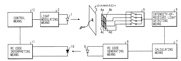
Referring first to FIG. 1, there is shown the
construction of the embodiment of the present invention.
In this figure, reference numeral 1 designates an infrared
light emitting diode (LED); and 2 a light modulating means
for driving the LED 1 by applying an amplitude modulation
signal having a frequency of 445 kHz thereto. These
devices, together with a light receiving element 10, a
remote control code interpreting means 11 and a control
means 12 which will be described later, are provided in a
unit to be controlled (e.g., a television receiver).
Further, a portion composed of elements from a
diaphragm or stop 3 to a light emitting element 9 is
2043339
-13-
provided in an operating part of a remote control device.
Incidentally, the diaphragm 3 is constructed such that only
a very-small-area portion 300 transmits light emitted from
the LED 1. Reference numerals 4a to 4d denote light
receiving elements which are positioned just posterior to
the diaphragm 3. As shown in FIG. 1, this embodiment
employs a combination of the four light receiving elements
the respective of which are arranged like a checker pattern
and have large light-receiving-areas.
Reference numeral 5 represents a switching circuit,
to which output signals of the four light receiving
elements are connected, for selecting one or more light
receiving elements from the four elements 4a to 4d and
sending light receiving signals outputted from the selected
elements to the next stage; 6 an
intensity-of-received-light determining means (hereunder
referred to simply as an intensity determining means)
connected to outputs of the switching circuit 5 for
quantitatively determining the intensity of light received
by the light receiving elements; 7 a processing means for
processing outputs of the intensity determining means 6; 8
a remote-control-code generating means (hereunder referred
to simply as a code generating means) for generating a
remote control code in accordance with results of
operations performed by the processing means 7; 9 an
`` 204~339
-14-
infrared LED which is driven in accordance with outputs of
the code generating means 8; 10 the light receiving element
for receiving a light signal from the LED 9; 11 the remote
control interpreting means for interpreting a remote
control code represented by the signal received by the
light emitting element 10; and 12 the control means for
performing general control of the light modulating means 2
and the remote control code interpreting means 11.
Referring next to FIG. 2, there is shown a
practical example of the circuit of a primary part of the
embodiment of FIG. 1. As is understood from a comparison
of FIG. 2 with FIG. 1, the processing means 7 and the code
generating means 8 are constructed by a microcomputer 22
and on the other hand the remote control interpreting means
11 and the control means are constructed by a microcomputer
25. The microcomputers 22 and 25 are one-chip
micorcomputers each of which includes a central processing
unit (CPU), a read-only memory (ROM) and a random access
memory (RAM) and an input-output (I/O) unit. Further,
reference numeral 26 denotes a CRT controller for showing
characters on the screen of a CRT; 27 an RGB video input
terminal from which an RGB signal converted by a signal
processing circuit (not shown) by using a composite video
signal; and an RGB video output terminal from which a
signal obtained by the CRT controller 27 by superposing
20433~9
-15-
another signal representing character or the like upon the
RGB signal.
In the circuit of the unit to be controlled, a
frequency modulating device 24 drives the LED 1 and sends a
modulated light signal to the operating portion. Further,
a signal issued by the light emitting element 9 is received
by the light receiving element 10 and a remote control mode
represented by the received signal is read by the
microcomputer 25. These operations are controlled by the
microcomputer 25 in accordance with a predetermined
procedure.
On the other hand, in the operating portion, the
diaphragm 3 is positioned immediately prior to the light
receiving element 4a to 4d. When the operating portion
into which the diaphragm 3 and the light receiving elements
4a to 4d are integrally incorporated is placed face to face
with the LED 1 at an initial position apart therefrom by
several meters, light emitted from the LED 1 impinges on
the central portion of a group of the light receiving
elements 4a to 4d through the diaphragm 3. If the entire
operating portion is then shifted upwardly and downwardly,
and leftwardly and rightwardly within a range of from - 30
degrees or so to + 30 degrees or so with respect to the
direction from the LED 1 to the original position thereof,
the relative direction in which light comes from the LED 1
204;~3;~9
-16-
to the operating portion changes. Thus, the position, on
which light from the LED 1 impinges, moves on the surface
of the light receiving elements 4a to 4d. This results in
change of a ratio of the quantity of light received by each
of the four light receiving elements 4a to 4d to that
received by another one of the elements 4a to 4d.
Subsequently, necessary one or more outputs of the
light receiving elements 4a to 4d are selected by using the
switching circuit 5. Thus, the light signals received by
the light receiving elements 4a to 4d of which the outputs
are selected by the circuit 5 are serially converted into
digital data by an analog-to-digital (A/D) converter 20.
Incidentally, an automatic gain control circuit 19 is
inserted prior to the A/D converter 20 in order to
compensate change of the intensity of the received light,
which is caused by change in distance between the operating
portion and the unit to be controlled. Then, the digital
data sequentially being outputted by the A/D converter 20
and representing the intensity of the light received by
each of the selected light receiving elements are read by
the microcomputer 22. Based on the thus read digital data,
a ratio of the intensity of light received by each of the
four light receiving elements to that of light received by
another one of the light receiving elements is calculated.
Thereby, it can be found how many degrees the operating
-17- 204~3~9
portion is oriented away from the direction of the original
position thereof from the LED 1 within the range of from -
30 degrees to + 30 degrees. Reference numeral 21
represents a switch, to which the microcomputer 22 is
connected for determining whether or not the switch 21 is
pressed down, for directing that a remote control operation
is started and for selecting an item of the remote control
operation.
Information on the direction of the operating
portion is generated by the microcomputer 22 as a remote
control code. In response to a signal representing the
generated remote control code which is outputted by the
microcomputer 22, a transistor 23 drives the light emitting
element 9 and causes an electric current flow therein,
thereby performing a transmission of a signal representing
the information on the direction of the operating portion
(namely, the remote control code) by using light.
The transmitted light representing the information
on the direction of the operating portion is received by
the light receiving element 10 provided in the unit to be
controlled. Then, a signal outputted from the light
receiving element 10 is connected to the microcomputer 25
which interprets the transmitted remote control code,
thereby finding the direction of the operating portion.
The CRT controller 26 displays a menu which is a list of
`_ Z043339
-18-
operation functions such as a picture quality regulation
and a sound regulation on the screen of the television
receiver as well as a cursor thereon based on the signal
transmitted from the operating portion and representing the
direction of the operating portion.
Referring next to FIGS. 3(A) and 3(B), there are
respectively shown an example of an image practically
displayed on the screen of the television receiver and
another example of an image displayed thereon when the
direction of the operatin~ portion is changed. FIG. 3(A)
illustrates an image displayed on the screen of the
television receiver corresponding to the unit to be
controlled. First, by first depressing the switch 21 of
the operating portion, an operation menu of FIG. 3(A) is
displayed by being superposed on an ordinary picture. When
the direction of the operating portion is changed, the
information on the direction of the operating portion to be
transmitted to the unit to be controlled is also changed.
At that time, the operation menu as well as a cursor is
displayed on the screen as illustrated in FIG. 3(B). When
the transmitted signal representing the direction of the
operating portion varies, the position of the cursor is
changed such that the cursor is always displayed at a
position, which is placed in the direction of the operating
portion, on the screen. Thereby, a viewer manipulating the
_ 20433~9
--19--
operating portion can feel that when the operating portion
is appropriately shifted toward the screen of the
television receiver, the cursor moves on the screen in
response to the shift of the operating portion. Moreover,
it can be realized that a function of selecting a desired
item of an operation by depressing the switch 21 again with
the cursor put on the indication of the desired item of an
operation on the screen is added to the remote control
device.
Next, an operation of the remote control device
constructed as described above will be described
hereinbelow by referring to a flowchart of FIG. 4.
Referring now to FIG. 4, there is illustrated a
flowchart of a program for performing an operation of the
microcomputer 22 provided in the operation portion of the
remote control device.
When the operating portion is not used, a state of
the switch 21 of the operating portion is detected in step
31 and the remote control device is placed in the wait
state in this step until the switch 21 is depressed.
When the switch 21 of the operating portion is
pressed down, the program advances to step 32 whereupon a
remote control code indicating that the switch is depressed
is transmitted once to the unit to be controlled. The unit
to be controlled is adapted to transmit to the operating
Z04~339
_ -20-
portion a sequence of pulses for a predetermined time as a
response signal. An operation of the unit to be controlled
will be described detailedly later. The predetermined time
is set to be equal to or longer than a time required for
performing processings to be performed in steps 34 to 46
which will be described later.
Next, in step 33, the operating portion of the
remote control device waits for a response signal in order
to determine whether or not the response signal is received
within another predetermined period of time. In case where
the operating portion cannot receive a response signal
transmitted from the unit to be controlled within the
predetermined period of time, the program returns to the
step 31 so that the remote control device falls into the
wait state once more. This is accomplished to prevent
consumption of a battery provided in the remote control
device in a meaningless case, for instance, in case where
the switch of the operating portion is depressed when the
operating portion does not face the unit to be controlled.
In contrast, in case where the operating portion receives a
response signal transmitted from the unit to be controlled,
the program advances to step 34.
In step 34, first, the switching circuit 5 is set
in such a manner that outputs of all of the light receiving
elements 4a, 4b, 4c and 4d are connected to the A/D
Z0433~9
-21-
converter 20. Then, the remote control device is placed in
the wait state for a while in step 35 until an operation of
the automatic gain control circuit 19 becomes stable.
Subsequently, in step 36, the intensity of light received
by the light receiving elements is measured. Namely,
output data of the A/D converter 20 is read by the
microcomputer 22 and is further held therein as data il.
Next, in step 37, the switching circuit 5 is set in
such a fashion that the outputs of all of the light
receiving elements 4a, 4b, 4c and 4d are separated from the
A/D converter 20. Then, in step 38, output data of the A/D
converter 22 is read by the microcomputer 22 and is held
therein as data i2 which indicates a quantity of noises
generated in the automatic gain control circuit 19 when the
gain of the operating portion is appropriately regulated
for the measured intensity of light and is later used for
performing an operation.
Next, for the purpose of examining which of the
light receiving elements 4a to 4d receives the light issued
from the LED 1, the switching circuit 5 is set in step 39
in such a manner to connect only outputs of the light
receiving elements 4a and 4c to the A/D converter 20 and
subsequently the intensity of light is measured in step 40
similarly as in step 36. The result of the measurement is
stored in the microcomputer 22 as data i3.
2043339
-22-
Similarly, the switching circuit 5 is set in step
41 in such a manner to connect only outputs of the light
receiving elements 4a and 4d to the A/D converter 20 and
subsequently the intensity of light is measured in step 42.
The result of this measurement is stored in the
microcomputer 22 as data i4.
A deviation x of the direction of the operating
operation in the x-direction is calculated in step 43 by
using the following equation from the data il to i4
measured as above described:
x = (i3 - i2) x 16 / (il - 12)
Next, a deviation y of the direction of the
operating operation in the y-direction is similarly
calculated in step 44 by using the following equation:
y = (i4 - i2) x 16 / (il - 12)
Incidentally, with relation to each of the
deviations x and y, a part after the decimal point is
discarded. By using the equations above described, the
deviations in the x-direction and y-direction are
represented by numbers of from 0 to 15, respectively. Next,
in step 45, it is determined which of 3 x 3 regions
obtained by dividing each of height and width of the screen
by 3 the operating portion is turned toward. To this end,
the program preliminarily contains a correspondence table
indicating the corresponding relation between values of the
2~433~9
-23-
deviation x and three columns (namely, a left, center and
right columns) each composed of three regions. In this
embodiment, the corresponding relation therebetween is
preliminarily determined as follows:
(1) If the value of the deviation x is in a closed
interval of from 0 to 3, the operating portion is turned
toward one of the regions of the left column;
(2) If the value of the deviation x is in a closed
interval of from 4 to 11, the operating portion is turned
toward one of the regions of the center column; and
(3) If the value of the deviation x is in a closed
interval of from 12 to 15, the operating portion is turned
toward one of the regions of the right column.
Thus, be referring to this correspondence table, it is
first judged from the value (0 - 15) of the deviation x
which of the three columns on the screen of the television
receiver the operating portion is turned toward. Similarly,
the program preliminarily contains a correspondence table
indicating the corresponding relation between values of the
deviation y and three rows (namely, a top, center and
bottom rows) each composed of three regions. Further, by
referring to this table, it is then determined from the
value (0 - 15) of the deviation y which of the three rows
on the screen of the television receiver the operating
portion is turned toward.
2043339
-
-24-
Next, in step 46, it is judged again whether or not
the switch 21 of the operating portion is depressed.
Incidentally, in case where the switch is kept depressed
since it is judged in step 31 that the switch is depressed,
it is regarded in step 46 that the switch is not depressed.
Only in case where the switch is depressed again after the
switch is turned off, it is regarded in step 46 that the
switch is depressed.
In case where the switch 21 is not depressed, the
program advances to step 48. In this embodiment, a remote
control code is preliminarily assigned to each of the nine
regions previously described. Namely, nine remote control
codes respectively indicating the nine regions are
preliminarily determined. In step 48, a remote control
code indicating one of the regions is transmitted to the
unit to be controlled. In contrast, in case where the
switch is depressed, the program advances to step 47
whereupon a remote control code indicating that the switch
is depressed is transmitted once to the unit to be
controlled. After transmitting this code, the program
returns to step 33 whereupon the operating portion waits
for a response signal transmitted in response to this code
by the unit to be controlled. Thereafter, the above
described operations to be performed in a loop comprised of
steps 33 to 48 are repeatedly effected.
-25- 20433~9
Referring next to FIG. 5, there is illustrated a
flowchart of a program for performing an operation of the
microcomputer 25 of the unit to be controlled.
First, it is checked in step 61 whether or not a
remote control code is presently received. If no remote
control code is received, the program advances to step 62
whereupon it is checked whether or not the menu is
presently displayed. If the menu is not displayed, it is
regarded that the unit to be controlled is in an ordinary
wait state. Further, the program returns to step 61 and
thus the unit to be controlled waits again for a reception
of a remote control code. In contrast, if the menu is
displayed, the program advances to step 63 whereupon the
menu is erased from the screen. Then, the program returns
lS to step 61 and the unit to be controlled falls into the
wait state again. As long as the operating portion is
turned toward the screen of the television receiver, the
operating portion and the unit to be controlled keep
performing the transmission of the remote control codes and
the response to the received remote control codes,
respectively. Therefore, interruption of transmission of
remote control codes can be regarded that the operating
portion of the remote control device is not turned toward
the unit to be controlled and that namely, a viewer stops
controlling the unit to be controlled.
20433;~9
-26-
In case where it is found in step 61 that a remote
control code is received, the program advances to step 64
whereupon the contents of the received remote control code
are interpreted. Subsequently, in step 65, it is checked
whether or not the received remote control code indicates
one of the regions in which the cursor is displayed. If
the received remote control code indicates one of the
regions, the program advances to step 66 whereupon the menu
is presently displayed. If not displayed, the program
returns to step 61 because information on the region in
which the cursor is displayed is useless when the menu is
not displayed on the screen. In contrast, if the menu is
displayed, a signal frequency-modulated by using a constant
frequency is first transmitted for a predetermined time
toward the operating portion in step 67. Then, the cursor
is actually displayed in the region indicated by the
received remote control code in step 68. Thereafter, the
program returns to step 61 and the remote control device
waits for the next remote control code.
In case where it is found in step 65 that the
received remote control code does not indicate the position
at which the cursor is displayed, the program advances to
step 69 whereupon it is checked whether or not the received
remote control code is a code (hereunder referred to as a
switch-depressing code) indicating that the switch is
-27- 2043339
depressed. If the received remote control code is the
switch-depressing code, the program advances to step 70
whereupon the menu is presently displayed on the screen.
If the menu is not displayed on the screen, the program
advances to step 71. In case where the switch-depressing
code is received when the menu is not displayed, an
operation of displaying the menu is performed in response
to this code. Thus, in step 71, the menu is displayed.
Subsequently, in step 72, a response signal is transmitted
to the operating portion. Then, the program returns to
step 61, so that the remote control device falls into the
wait state. In case where the switch-depressing code is
received when the menu is displayed, this code means that a
command indicated at the position at which the cursor is
presently displayed in the menu is performed. In step 73,
a response signal is transmitted to the operating portion.
Then, a command indicated at the position at which the
cursor is presently displayed in the menu is performed in
step 74. Thereafter, the program returns to step 61 and
thus the remote control device falls into the wait state.
With the arrangement of the above described
embodiment, in case of applying the present invention to a
television receiver, a viewer can select a desired item of
operations by first turning the operating portion itself
toward the item of the menu displayed on the television
-28- 2~433~9
receiver and next depressing the switch 21 of the operating
portion. Thus, in case of using the remote control device
of the present invention, a selection of an item of
operations is straightforward and therefore the remote
control device according to the present invention is easy
to manipulate. Moreover, the remote control device of the
present invention can be manipulated without seeing the
keyboard of the remote control device and namely can be
easily manipulated even in the dark.
While a preferred embodiment of the present
invention has been described above, it is to be understood
that the present invention is not limited thereto and that
other modifications will be apparent to those skilled in
the art without departing from the spirit of the invention.
The scope of the present invention, therefore, is to be
determined solely by the appended claims.