Note: Descriptions are shown in the official language in which they were submitted.
~043343
P-1735
A ARATUS AND ~ETHOD FOR A
CATHETER ADAPTER WITH VALVE
1 Field of the Invention. This invention relates
to a bloodless over the needle catheter and more
particularly, to a valve integral with a catheter adapter
having a resealable septum through which the needle
passes.
2. Backqround. Over the needle catheters are used
for peripheral intravenous entry into the vasculature of a
patient. The disposable medical product is packaged as an
assembly of a catheter adapter with its catheter and a
needle and hub assembly conjugated with the catheter
adapter such that the needle passes through the catheter
tube and extends a slight distance beyond the distal tip
thereof to provide a sharpened point for penetra~ion
through the skin of the human or animal being
catheterized. During catheterization blood flows due to
the vascular blood pressure through the hollow needle and
into the transparent needle hub so it is visually apparent
that the tip of the needle has reached into the blood
vessel. Thereafter, the needle and hub as an assembly are
removed from the catheter while the practitioner places a
finger against the skin of the human or animal to compress
the skin and the vessel therebeneath and distal to the
catheter tube and thereby prevent the flow of blood
through the catheter tube, into the catheter adapter and
out onto the patient and the bedding. This approach has
been used and is essentially bloodless, however, with
greater concern about the spread of communicable diseases,
particular those such as Acquired Immune Deficiency Virus
and Hepatitis which are presently incurable, a need for a
better technique, one that is automatically bloodless is
required.
P-1735 2~43343
Use of an over the needle catheter is most
conveniently performed by a single handed one finger
technique. In particular, the needle and catheter
assemblies are concentric and conjugate when they are
inserted through the skin of the human or animal and into
the vasculature. Once flashback is noted in the hub of
the needle, a finger is generally placed on a portion of
the catheter adapter and two other fingers of the same
hand, one of which may be the thumb are used to control
the hub. The finger on the catheter adapter pushes toward
the patient such that the catheter and its adapter as an
assembly are separated from the needle and hub assembly by
the use of one hand. Practitioners usually use the other
hand to hold the patient's arm steady, thus comforting the
patient and enabling appropriate control of the
procedure. It is of value to be able to withdraw the
needle and hub assembly from the catheter and adapter
assembly without having to use the hand which positions
the patient's arm to also press against the catheter tube
and stop blood flow. In that regard, a catheter adapter
which includes an integral valve to automatically prevent
blood loss would be of vaiue in that the single handed
technique described could be used without concern or need
for the additional hand to prevent loss of blood from the
catheter adapter.
Catheter adapters with manually actuated valves are
shown in U.S. Patents 3,811,440 and 3,856,010. Those
manually actuated valves require that the valve in the
catheter adapter be depressed during and after withdrawal
of the needle and in that way the technique is similar to
depressing the vessel but for the added expense of the
valve. Valves actuated by the luer fitting on a syringe,
P-1735
administration set or the like are shown in U.S. Patents
4,387, 879 and 4,842,591. Those valves are normally
closed and the insertion of the luer fitting into the
housing containing the valve compresses the valve and
opens a flow path.
U.S. Patent 3,831,629 discloses a two~piece check
valve having a sleeve like valve body and valve element
reciprocal therewithin. The valve element has an
elastomeric rear end portion integral therewith and held
in axial compression such that it is constantly urged
forward toward a valve closed position. The proximal end
of the valve element is crimped radially inward to form a
fluid passing abutment and means is provided to guide the
valve element for reciprocation within the body and
maintain its concentric relative thereto. The mechanism
is complicated in that a number of pieces are required to
provide the integral valve and there is no showing of the
valve in connection with an over the needle catheter
assembly which permits a needle to pass through the valve.
U.S. Patent 4,512,766 shows an assembly and needle
hub with a needle passable through a penetratable self
sealing material in the assembly. A slit or puncture is
provided in the proximal end of the valve member which is
spread upon axial compression by the luer of a syringe or
the like. The slit provides a passage for the needle and
also acts as the valve. Radial tension across the slit is
relied on to close the valve member.
U.S. Patent 4,874,377 shows a self occluding cannula
assembly. The occluding means permits withdrawal of the
needle and is in the form of an aperture which is either
P-1735 2~4~3~3
dialated by the tapered luer of a syringe or the like or
penetrated by a needle passed therethrough. The aperture
is formed by beveling the outward surface of the occluding
member in each direction from the aperture such that a web
of material closes the aperture. The aperture is torn by
the radial spread of the forced luer and is eased by the
thin material of the web. Resealing the aperture formed
through the web is doubtful.
U.S. Patent 3,385,301 shows a balloon catheter with
a deformable one way inflation valve wherein a resilient
valve member is captured in one leg of a Y-adapter through
which a syringe may be used to collapse the valve thus
opening that path to air for inflating the balloon.
U.S. Patent 4,681,132 has a check valve with a
pre-set cracking pressure. The resilient member in this
valve is biased by a plug which can be of varying heights
adjusted to account for different tolerances of the valve
bodies and the like. How the plug allows the manufacture
with a pre-set cracking pressure of this normally closed
valve is the idea of this disclosure.
The aforesaid luer activated valves do not include
in their designs sufficient capability for use with luers
of varying dimensions. The engagement length of luer
fittings can vary as much as 2.5 mm. and still be
considered to meet standard specifications. A positive
seal upon withdrawal of the needle during the single
handed introduction of an over the needle catheter
assembly is required. Thes0 luer activated valves do not
provide reliable activation of an automatic valve within
the catheter adapter for the intravenous catheter. The
P-1735
20433~3
catheter adapter with a valve as shown and disclosed in
the present Specification overcomes the problems of the
aforesaid valves.
SUMMARY 0~ THE INVENTION
An over the needle catheter and catheter adapter has
an integral valve in a catheter adapter. The catheter
adapter may have a distal part and a proximal part joined
together to form a passage therethrough along an axis
thereof. The distal part connects to a catheter tube
providing fluid communication therewith and through the
passage. A needle hub assembly has a hub which may
conjugate with the proximal part of the catheter adapter
and has a needle extending from the hub along the axis of
the catheter adapter and through the passage when the hub
is within the proximal part of the catheter adapter.
A valve assembly is most preferably positioned
within the passage about the axis and has an elongate
resilient member captured within the passage and between
the distal part and the proximal part for a compression
fit. The compression of the elongate resilient member
prevents fluid communication through the passage. A
proximal portion of the valve assembly is provided to be
engaged by a fluid dispenser fitting such as a male luer
connector fashioned to extend into the passage of the
proximal part and contact the elongate resilient member.
Axial compression of the elongate resilient member occurs
when the fluid dispenser fitting is within the catheter
adapter proximal part and opens the normally closed valve.
P-1735 ~
A valve seat disposed within the passage and on the
proximal part is formed as a generally frusto-conical
surface located coaxial about the axis and facing the
distal part of the catheter adapter in position to engage
a chamfered surface on the elongate resilient member. The
seat and the chamfered surface form a seal and prevent
fluid communication when the elongate resilient member is
compressed between the distal part and the proximal part
but allow fluid communication when the seal is broken by
axial compression of the elongate resilient member upon
engagement of the fluid dispenser fitting with the
proximal portion.
An internal cavity on the elongate resilient member
extends axially and distally from the proximal portion
providing a septum like end across the elongate resilient
member for permitting the needle to pass through the
septum like end of the elongate resilient member in a
resealable fashion upon placement and withdrawal of the
needle through the septum like end. The distal part and
the proximal part each may be provided with conjugating
surfaces arranged to fit together in mating engagement
forming the passage through the catheter adapter. The
elongate resilient member is preferably molded of a
resilient material and has a flanged end for supporting
the chamfered surface. The elongate resilient member has
a diametrically reduced cylindrical body extending to the
septum like end. An annular space formed about the
diametrically reduced cylindrical body terminates in a
distal area in the distal part.
The diametrically reduced cylindrical body and
internal cavity therethrough act to provide an area of
weakness permitting the elongate member to preferentially
P-1735 ~43343
collapse under axial compression by the fluid dispenser
fitting. A proximal end of the internal cavity of the
elongate resilient member in the preferred embodiment
conjugates with a collar disposed in axially alignment
with the open end thereof and shaped to abut with the
fluid dispenser fitting when extended into the distal
part. The distal area may include flow channels which
extend between the annular space and the distal part
wherein the catheter tube joins in fluid communication the
passage.
A method of providing a catheter adapter with an
integral valve having an elongate resilient member which
allows a needle to pass through the valve in a resealable
manner includes the catheter adapter having a distal part
and a proximal part which are designed to fit together and
capture the elongate resilient member. The method has the
steps of locating either of the parts along an axis for
placing the elongate resilient member along the axis of
the aligned part. Thereafter the step of placing the
remaining part along the axis and moving it along the axis
toward the other part captures the resilient member in a
passage defined by the assembly of the parts.
Engaging the axially aligned parts with each other
and about the elongate resilient member to axially
compress the elongate resilient member in the passage in
which the resilient member is captured is the next step.
Forcing the elongate resilient member against a valve seat
to seal transversely the passage and prevent flow
therethrough is the valve forming step of the preferred
method. Placing a needle carried on a hub along the axis
and through a septum like end of the elongate resilient
member allows the needle to be withdrawn from the septum
like end to thereafter reseal the passage.
P-1735 204334~
The method step of engaging is provided by fitting
the parts and applying fastening means to secure in fluid
tight manner the engagement between the parts. It is
preferred that the elongate resilient member be placed
into the distal part first before the proximal part is
applied to complete the catheter adapter and compress the
elongate resilient member within the passage formed
therethrough.
BRIEF DESCRIPTION OF THE DRAWINGS
Figure l discloses an exploded perspective view of a
preferred embodiment of a catheter adapter with an
integral valve.
Figure 2 discloses side cross-sectional view of the
valve shown in Figure 1 except the valve is fully
assembled with the parts shown in the positions they would
be in before insertion of the needle and hub assembly
therethrough.
Figure 3 is a cross-sectional view similar to Figure
2 with the needle and hub assembly shown inserted through
an elongate resilient member of the valve.
Figure ~ is a cross-sectional view similar to Figure
2 with the needle and hub assembly removed and a luer
fitting inserted to compress the elongate resilient member
of the normally closed valve.
Figure 5 discloses an exploded perspective view of
the preferred embodiment of a catheter adapter with an
integral valve of Figure l with a section of the adapter
removed so that the relationship of the parts may be shown.
P-173s ~3343
Figure 6 discloses a side cross-sectional view of an
alternate valve with the parts shown in the positions they
would be in before insertion of the needle and hub
assembly therethrough.
Figure 7 is a perspective view of the elongate
member shown folded or collapsed as it would be under
axial loading.
Figure 8 is a view in cross section as would be seen
along line 8-8 of Figure 7.
Figure 9 is a view in cross section as would be seen
along line 9-9 of Figure 7.
DETAILED DESCRIPTION OF THE DRAWINGS
While this invention is satisfied by embodiments in
many different forms, there is shown in the drawings and
will herein be described in detail, a preferred embodiment
of the invention and an alternate, with the understanding
that the present disclosure is to be considered as
exemplary of the principles of the invention and is not
intended to limit the invention to the embodiment
illustrated. The scope of the invention will be measured
by the appended claims and their equivalents.
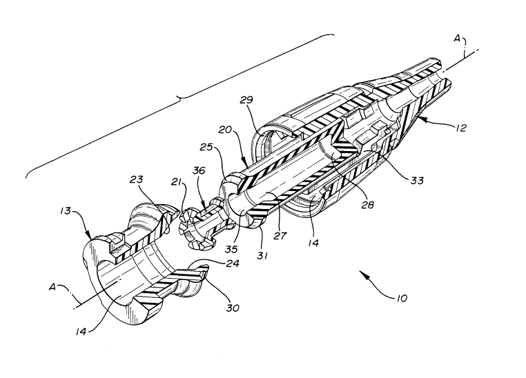
Figure 1 is an exploded perspective view of the
preferred embodiment of catheter adapter 10. An integral
valve 11 is in a catheter adapter 10. The catheter
adapter 10 may have a molded plastic distal part 12 and a
molded plastic proximal part 13 joined together to form a
P-1735
33~3
passage 14 therethrough along an axis "A" thereof. The
preferred plastic is polypropylene but polycarbonate,
acrylic and PVC are also satisfactory substitutes. The
distal part 12 connects to a catheter tube 15 providing
fluid communication therewith and through the passage 14.
In Figure 3 a needle hub assembly 16 has a hub 17 which
may con~ugate with the proximal part 13 of the catheter
adapter 10 and has a needle 18 extending from the hub 17
along the axis "A" of the catheter adapter 10 and through
the passage 14 when the hub 17 is within the proximal part
13 of the catheter adapter 10.
A valve assembly 19 is most preferably positioned
within the passage 14 about the axis "A" and has an
elongate resilient member 20 captured within the passage
14 and between the distal part 12 and the proximal part 13
for a compression fit. The elongate resilient member 20
is most preferably molded of a flexible material such as
rubber, urethane, latex, synthetic polymers or other
elastomers. The preferred durometer of the elongate
resilient member 20 is 40 to 50 Shore A. The compression
of the elongate resilient member 20 prevents fluid
communication through the passage 14, as will be
explained. ~ proximal portion 21 of the ~alve assembly 19
is provided to be engaged by a fluid dispenser fitting 22
fashioned to extend into the passage 14 of the proximal
part 13 and contact the elongate resilient member 20. As
shown in Figure 4, the axial compression of the elongate
resilient member 20 occurs when the fluid dispenser
fitting 22 is within the proximal part 13 and opens the
normally closed valve assembly 19.
-10-
P-1735
2~a~33~3
A valve seat 23 as seen in Figures 2, 3 and 4 is
disposed within the passage 14 and is on the inside of
proximal 13 part. The valve seat 23 is formed as a
generally frusto-conical surface 24 located coaxial about
the axis "A" and facing the distal part 12 of the catheter
adapter 10 in position to engage a chamfered surface 25 on
the elongate resilient member 20 as best seen. The valve
seat 24 and the chamfered surface 25 form a seal 26 and
prevent fluid communication when the elongate resilient
member 20 in Figure 2 is compressed between the distal
part 12 and the proximal part 13 but allow fluid
communication when the seal 26 is broken by axial
compression of the elongate resilient member upon
engagement of the fluid dispenser fitting 22 within the
proximal portion 13. The closed and open positions of the
valve assembly 19 are shown in Figures 2 and 4.
An internal cavity 27 on the elongate resilient
member 20 extends along axis "A" and distally from the
chamfered surface providing a septum like end 28 across
the elongate resilient member 20 for permitting the needle
18 to pass through the septum like end 28 of the elongate
resilient member 20 in a resealable fashion upon placement
and withdrawal of the needle through the septum like end
28. Figure 3 shows the needle 18 passing through the
septum like end 28 of the elongate resilient member 20.
The distal part 12 and the proximal part 13 each may be
provided with conjugating surfaces 29 and 30 respectively
arranged to fit together in ma~ing engagement forming the
passage 14 through the catheter adapter 10. The elongate
resilient member 20 as mentioned is preferably molded of a
resilient material and has a flanged end 31 for supporting
the chamfered surface 25. The elongate resilient member
P-1735
204~
has a diametrically reduced cylindrical body 32
extending to the septum like end 28. An annular space 33
formed about the diametrically reduced cylindrical body 32
terminates in a distal area 34 in the distal part 12.
The diametrically reduced cylindrical body 32 and
internal cavity 27 therethrough act to provide weakness
permitting the elongate resilient member 20 to
preferentially collapse under axial compression by the
fluid dispenser fitting 22. A proximal end 35 of the
internal cavity 27 of the elongate resilient member in the
preferred embodiment conjugates with a collar 36 disposed
in axially alignment with the opening thereof. The collar
36 is shaped to abut with the fluid dispenser fitting 22
when it is extended into the distal part 12. The distal
area 34 may include flow channels 37 which extend between
the annular space 33 and the distal part 12 wherein the
catheter tube 15 joins in fluid communication the passage
14, see Figures 2, 3, 4 and 6. The catheter 15 is held in
the distal part 12 by an eyelet 38 preferably formed of
metal; the eyelet 38 fits inside the catheter 15 and
expands it against the inside of the distal part 12.
Figure 6 shows the alternate embodiment and all of
the component parts therein are identical to those shown
and described in connection with Figures 1, 2, 3, 4 and 5
except for the elongate resilient member 20 and collar
36. In Figure 6 a single molded flexible piece 39 is
substituted for the resilient member 20 and collar 36. In
particular, single piece 39 has a hollow cylinder 40
terminating distally in a pierceable diaphragm 41. The
hollow cylinder 40 has a partially split and
longitudinally open annular extension 42 about its
P-1735 .~0433~
proximal end so that flow may pass through the proximal
part when the piece 39 is axially compressed. Between the
partially split and longitudinally open annual extension
42 and the hollow cylinder 40 is an enlarged ring 43
haviny a beveled shoulder 44 to seal against valve seat 24
of distal part 13. Hollow cylinder 40 functions
identically to the elongate resilient member 20 in that
the partially split and longitudinally open annular
extension allows flow to pass to and across the beveled
shoulder 44 when same is displaced from ~he valve seat 24.
A method of providing the catheter adapter lO with
an integral valve having the elongate resilient member 20
which allows the needle 18 to pass through the valve in a
resealable manner includes the catheter adapter having a
distal part and a proximal part which are designed to fit
together and capture the elongate resilient member. The
method has the steps of locating either of the parts 12
and 13 along an axis for placing the elongate resilient
member 20 along the axis of the aligned part 12 or 13.
Thereafter the step of placing the remaining part 12 or 13
along the axis and moving it along the axis toward the
other part 12 or 13 to capture the resilient member 20 in
a passage defined by the assembly of the parts 12 or 13.
Engaging the axially aligned parts 12 and 13 with
each other and about the elongate resilient member 20 to
axially compress the elongate resilient member 20 in the
passage in which the resilient member 20 is captured is
the next step. Forcing the elongate resilient member 20
against a valve seat 23 to seal transversely the passage
and preven-t flow therethrough is the valve forming step of
the preferred method. Placing the needle l~ carried on
P--173s
2~433~3
the hub 17 along the axis "A" and through a septum like
end 28 of the elongate resilient member 20 allows the
needle 18 to be withdrawn from the septum like end 28 to
thereafter reseal the passage 14.
The method step of engaging is provided by fitting
the parts 12 and 13 and applying fastening means, e.g.
glue, cement, RF welding, or mechanical means to secure in
fluid tight manner the engagement between the parts 12 and
13. The elongate resilient member 20 is first placed
along the axis "A" and within the distal part 12 before
the proximal part 13 is applied to complete the catheter
adapter 11 and compress the elongate resilient member 20
within the passage 14 formed therethrough.
Figure 4 shows the valve 11 in the open position.
The flow is from the luer fitting 22 through reliefs 4S in
the collar 36. The collar 36 is rigid so that radial flow
through the reliefs 45 may take place even though the
elongate resilient member 20 is compressed by the fitting
22. The flow channels 37 include, in the preferred
embodiment, longitudinal grooves 46 on the inside of the
distal part 12 permitting the flow to easily pass through
the annular space 33 between the elongate resilient member
20 and the distal part 12. The flow channels 37 terminate
distally in exit ports 47 which provide support shoulders
48 therebetween to hold the septum like end 28 when the
elongate member 20 is compressed. The support shoulders
48 keep the exit ports 47 patent allowing flow to pass
from the flow channels 37 through the exit ports 47 and
into the catheter 15. Should the flow direction be
opposite that shown in Figure 4, the valve 11 will work
the same way.
P-1735 2~43343
The reduced cylindrical body 32 on the elongate
resilient member 20 is designed to encourage the folding
of the reduced cylindrical body 32 of the elongate
resilient member 20 during compression such that the
length reduction is sufficient to permit flow through the
passage. The preferred design is arranged with ribs 49
placed longitudinally along the inside of the reduced
cylindrical body 32 so that folding takes place in
preferred directions. As illustrated in Figure 4 the
reduced cylindrical body 32 is bowed under compression.
It is preferred that the reduced cylindrical body 32 fold
as shown in Figures 7, 8 and 9. The ribs 49 reinforce the
reduced cylindrical body 32 and encourage the folding as
shown so that transverse folds 50 are a direct result of
the positioning of the ribs 49 across from and ninety
degrees relative to one another. The transverse folds 50
are thus a result of the placement of ribs 49 and the
compression.
The septum like end 28 is held in the distal part 12
in radial compression by an interference fit in the distal
area 34. The slightly smaller size and similar shape of
the distal area is selected to hold the septum like end 28
of the elongate resilient member 20 so that the radial
compression thereacross assures that the resealable nature
of the septum like end 28 is maintained after the needle
18 is removed.