Note: Descriptions are shown in the official language in which they were submitted.
3 9 ~ ~
B_~ou~ na ~ y <;)1~ Inv0~a
The invention pertain~ to a bag for the packaglng of product~
or commodities of the type having a sealed .inner pouch within a
multiple ply enclosing bag, and methods for making the bag, and for
~illing and sealing the bag.
More particularly, the invention is directed toward an
improvement in a multiwall bag of the type formed from a tubular
flat blank.
The invention is also directed to the type of product packaye
that includes a standard pinch bottom for the outer multiple plies
at th~ bottom end of the bag. In this type o~ bag the commodity-
holding pouch is formed from an inner plastic ply that is heat
sealed at the pinch closure of the outer enclo_ing bag and open at
the opposite end for receipt of a product to be packaged. Upon
filling the bag to a desired amount, the inner plastic ply is heat
sealed to close the open end and thereby create a sealed pouch
which may remain detachably bonded to the top end o~ the outer
plies or optionally might be severed to separate the plastic pouch
~rom the top end of the outer plies. In this r~gard the invention
is further directed toward tho~e product bags wherein the ~ultiple
outer plies are subsequently ~olded and bonded together at the top
cut following the heat s~aling of the plastic ply.
The invention further provides for an improvement in multiwall
type bags as described, which utilize an adhesive bonding, or
equivalent, of the inner plastic ply to,the ~nnermost ply of the
outer plies, whexein the outer plie~ comprise a plurality of
contiguous overlying non-heat sealable plies bonded together.
The present invention is an improvement ~n the packaging arts
which have heretofore evolved, such as that disclosed in U.S.
Patent No. 4,088,264, entitled "Multiwall Pouch Bags for Detached
Packaging of Commoditiesl', issued May 9, 1978 to Vogt. In this
patent, open ended, pinch botto~, multiwall bags are disclosed as
having an inner ply o~ heat sealable plastic material, such as
polyethylene, and one or ~oxe outer plie~ of a non;heat sealable
~ . ~ 2 ~
material, such as paper or equivalen~. The pla8ti¢ ply iS bond~d
at both bag ends to the contiguous outer plies during bag
manu~acturing and heat sealed and severed at the lower heat sealed
zone during the bag bottoming operation. At the top opening of the
bag, following the introduction of a product, commodity, or items,
the plastic ply is heat sealed to closure and must be severed along
the upper heat seal zone prior to closure of the outer plies. The
result is a fully closed plastic bag inside of the ~ully closed
paper bag. The problems that exist with thls de~ign are that when
the unfilled bag is standing ready to be filled, the inner plastic
bag is shorter in length than the enclosing outer paper bag. As
the commodity is discharged or placed into the bag during the
filling process there often are uneven and exces~ive pressures
exerted on the lower plastic seal creating a potential for seal
failure or pinhollng along the bottom heat seal zone. Alsn, a
slight collapsing of the outer bag can be caused as th~ weight from
the commodity ~orces the upper portion of the bag downward, thus
creating problems with the integrity of the upper closure.
The present invention greatly reduces the possibility of
bottom plastic seal failure, or bag collapse during the bag filling
process, and offer~ signi~icant improvement over previously known
techniques and bag constructions.
B~I~F 8~M~aRY OF T~B INV~TI~
The invention solves the foregoing problems in multiw~ll bag
construct-ions and methods of making them by providing an inner
plastic bag that is as long as the outer pap0r bag during the
filling process. The bottom plastic seal is folded (wrapped~
around the pinch bottom fold line at the bag bot~om during ~he bag
bottoming operation, but i~ not adhered or bonded to the contiguous
outer plie~. Instead, it is loosely, or freely folded with the
outer contiguou~ plies which provide~ for partial restraint thereat
during filling by virtue of staying in place at the botto~ pinch
closure. Therefore, the lower plastic heat seal is protect8d from
;-; 2 ~
excessive pressures during the bag ~illing process. Likewise,
because the inner plas~ic pouch i5 a~ long a~ the outer paper bag,
the probability of collapsing the upper portion o~ the bag during
the bag ~illing process has been reduced, giving greater insurance
of a proper closure o~ the open top bag end once the product or
commodity ha~ been introduced.
BRI~F D~ACRIP~ION OF TB~ DRAWI~G~
The invention will be further described in detail with
re~erence to the accompanying drawings wherein like reference
numerals throuyhout re~er to the same elements and wherein
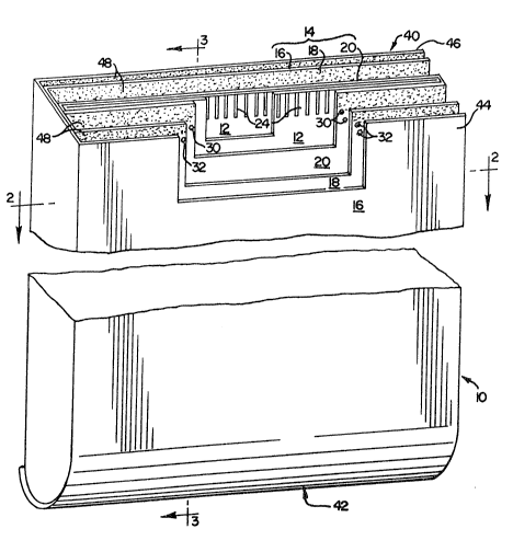
Fig. 1 is a perspective, partially broken away, view of the
multiply bag in accordance with the invention ready to be filled
by the packer with a commodity or the like;
Fig. 2 is a horizontal cross section of the bag ~hown in Fig.
1 taken along the line 2-2 looking in the direction of the arrows;
Fig. 3 is a vertical cross sectional view oP the bag as shown
in Fig. 1 taken along the line 3-3 looking in the direction of the
arrows;
Fig. 4 is a vertical cross sectional view o~ a tubular bag
blank which when subjected to the method steps of the present
invention results in the bag as shown in Fig. l;
Fig. 5 shows the heat sealing at the lower end of the inner
plastic ply of the blank as illustrated in Fig. 4 by the u~e of hot
compression bars applied to the outer sur~aces of the ontisuous
outer plies;
Fig. 6 is a vertical cross sectional view of the bag in
accordance with th2 invention filled with a product and showing a
heat sealing across a top zone of the inner plastic ply thereby
forming a closed pouch;
Fig. 7 is a vertical cross sectional view of the filled bag
showing an optional severance o~ th~ inner plasti~ ply during the
heat sealing at the top sealing zone thereoi;
.... . .
~ 3~J~
Fig. 8 is a vertical cross sectlonal vlew o~ the upper portion
of the filled bag illu~trating a heat~ng d~vice for lique~ying a
hot melt adhesive previously applied to the upper ends o~ the outer
plies;
Fig. 9 is a side view of the upper portion of the ~illed bag
with the outer plies folded over for passage between two pressure
rollers to close the bag;
Fig. lO is a sche~atic view of the sealing end closiny of the
top end of the bag as illustrated in Figs. 6 9;
Fig. 11 is an elevational view o~ a ~illed and sealed bag
having slits in the outer ply for the rPmoval o~ the contiguous
outer plies;
Fig. 12 is a perspective view of a filled and sealed bag as
in Fig. 11; and,
Fig. 13 is a perspective view of the bag o~ Fig. 12 showing
the filled and sealed plastic inner pouch with ~he contiguous outer
plies stripped away.
taila~ Des~riptio~ o~ the I~entio~
Throughout the ~igures the re~erence numeral 10 is used to
denote the bag made in conformance with the invention. In Fig. 1
the completed bag 10 in accordance wi'ch my invention will be seen
to comprise an inner tubular ply 12 of heat sealable material,
which may ba polyethylene, or equivalent, w~thin an outer tube 14
formed of a plurality of contiguou~ laterally of~set plie~ 1~, 18
and 20. The plies 16, 18, 20 are made of a non~heat sPalable
material, such a.~ paper. With respect ~o the horizontal cro~s
sectional view of the bag 10 shown in Fig. 2, it will be understood
that the continuous plies 16, 18, 20 are laterally of~set so that
vertical overlapping edge~ are ~paced iaterally around the bag 10
wherein ply 16 is overlapped at edges 16' 16n; ply 18 is overlapped
at edges 18' 18t~ and ply 20 i8 overlapped a~ edges 20' 20~. The
inner tubular ply 12 also i5 overlapped.~nd laterally o~fse~ a~ its
edges 12' and 12~. The tubular formation i8 made in a blank ~orm
a~3~ ~
22 illustrated in Fiy. 4, which blank is produced on known step end
tuber devices. The inner pl~stic ply 12 is heat ~eal~d at the
overlapping edges 12', 12" and the overlapping edges of the
multiple non-heat sealable plies 16, 18, 20 are adhesively bonded
thereat, such as by a hot melt adhesive applied in a known manner.
During the formation of the blank 22 ~he inner ply 12 is
circumferentially bonded at 2~ at the top end thereo~ to the
contiguous innermo~t paper ply 20. From the bond 2~ downwardly the
inner ply 12 remains detached ~rom the outer tube 14 from 26 to 28
therealong. The outer contiguous paper plies 16, 18, 20 are
bonded, pre~erably by dots of adhesive, at both the top and bottom
ends of the blank 22 and indicated at 30, 32 in Fig. 1.
The blank 22 is subjected to the method steps of the present
invention to result in the formation of the bag 10 shown in Figs.
1-3 as will now be explained. Attention is directed to Fig. 5
wherein a first s~ep is made ~y heat sealing the plastic ply 12
across a bottom closure zone 34 cau~ed by apply~ng heat bars 36,
38 at opposite sides of the outer contiguous non-heat sealable
plies 16, 18, 20. As indicated by the arrows, the heat bars 36,
38 are urged toward each other to clamp agains~ the blank 22 and
thereby form the heat seal closure zone 3~ whereupon they are moved
in opposite directions so that the heated plastic cool~ to closure.
The heat bars 36, 38 reach a temperature level sufficient to cause
the inner ply 12 to become plastic and create a fu~ion bonding at
the zone 34. The temperature and time required to effectiv~ly seal
the plastic, such a~ polyethylene, will vary depending upon the
thickness of the ~aterial used ~or the inner ply 12 and the total
thickness of the outer tube 14.
Next, the bottom of the paper plies of the blank 22 are
closed. A standard pinch bottom closure is effected by folding
about fold line B-B show~ in Figs. 4 and 5 to create a closure at
the lower ~nd of the outer tube 14. The contiguous outer plies 16,
18, 20 are oppo~itely ~tepped at both end3 of the blank 22, as
shown in Figs. 1, 3 and 4. Accordingly a pinched clo~ure may be
made at both ends of the bag 10. After m~king the clo~ure at ~he
2 ~ llY ~ IJ ~
bottom end, a folded overlapping arrangement is created as shown
in Fig. 3. With reference to Figs. 1, 3, 4 and 5 it wlll be seen
that the bag is open at the top at 40, and i~ clo~ed at the bot~om
end 42. At the open end 40, each ply is stepped up startinq at an
outermost front ~4 of the ply 1~ and proceeding to an outermost
rear 46 of ply 16, with the exception o~ the inner plaskic ply 12,
which is flush cut evenly with ~he innermost non-heat sealable ply
20~ At the closed end 42, shown in Fiys. 1, 3 and 6, the outer
contiguous plies 16, 18, 20 are stepped in the exact reverse order
as at the open end 40 with the plas~ic ply 12 flush in the same
way. Heat reactivatable hot melt adhesive 48, shown by the
stippling in Fig. 1, is applied to at least portions of the exposed
steps of both the end 40 and the end 42 of the tuhular blank 22.
In the case of the end 42, the pinch closure is made while the hot
melt adhesive is still in the molten state and thus the closure is
completed in a standard pinch bottom fashion. The inner plastic
ply 12, which has been thermally ~ealed at zone 34, is loosely
folded at the closed end 42, but not bonded, with th~ outer tube
14. It will there~ore be apparent at the clo~ed end 42 tha~ th~
zone 34 is loosely and freely folded to lie between folded step
portions of the outer contiquous plie~ ~8 and 20.
Closing the open end ~0 i8 undertaken when the bag has been
filled with a commodity or product 50 to be packaged generally in
the same way as the closed end 42. The inner plas~ic ply 12 is
fused to closure by the application of heat ad~acent to, but below,
the bond 24 across an upper region or zone generally re~erenced at
52 as sho~n in Fig. 6. The heat sealing i5 made by th~ application
of hot ~ompression bars 54, 56 ~o the outer side~ o~ the outer tube
14 on opposite sides of the bag 10, similar to the action of the
bars 36, 38 illu~trated in Fig. 5. Optionally, the inner ply 12
~ay ~e, but not need be, severed as ~own in Fig. 7 by the
application o~ beveled compreR~ion rollers 58, ~0 on oppo~ite sides
of the heat sealed zone 520 The severance would depend upon the
needs o~ the packer and also upon the clo~inq equipment used by the
packer of the commodity or product 50.
3 ~ ~ 1
Following the heat seallng at 52, ~r at th~ severance therea~
by means of beveled compression rollers 58, 60, the pre-applied hot
melt adhesive 48 at the open end 40 ls heated, such a~ by a hot air
blast 62, generally at the open end 40 and in the direction of the
steps of the outer plies. When melted, the outer contiguous plies
~4 are folded about fold line A-~ shown in ~igs. 6 and 7 for
sealing the opposed outer walls by m~ans of passing ~he bag be~ween
pressure rollers 64, 66 illustra~ed in Fiq. 9. The sequence for
the s~eps explained in conjunction wi~h Figs. 6-9 for the closure
of ~he open end 40 are fur~her illustrated in the schematic
illus~ration o~ Fig, 10. After the co~modity or product 50 is
~illed to the desired amount within the inner plastic pouch 12, the
filled bag lo is placed on an endless conveyer bel~ 68 and carried
thereon between the opposing hot compression bars 54, 5~ to cause
the inner ply 12 to be heat sealed at the zone 52 at the open bag
end 40. The bag 10 is then carried between the optional beveled
severing rollers 58, 60 and then passed through the hot air blast
62 to reactivate the hot ~elt adhesive ~8. ~hile the adhesive is
în the melted state, the bag 10 is passed through a folding device
70, which may include the pressure rollers 64, 66, as ~hown in Fig.
9. To allow for adhesive set, the bag is then passed betwe~n a
pair of pressure belts 72 toward the end of the conveyer belt 68
in fully packagsd ~orm generally denoted at 74.
Thus, after the filled bag 10 illus~rated in Fig. 9 is closed
in the manner described ~or clo8ing the open end 40, the packaged
content~ 50 will be completely sealed wi~hin the pla tic plie~ 12,
which provides an inner sealed pouch closed at both ends ~0 and 42.
At end 42, the heat sealed folded zone 34 may be wholly detached
and removed from the outer plies 14 because the fold 34 is not
adhered there, but is loosely restrained between the folded plies
16, 18. Hence, when the outer paper plies 16, 18, 20 are ~tripped
away as shown in Fig. 13, ~he heat sealed pla~tic pouch 12 is left
intact r sealed, clean and ready ~or use of the enclosed protacted
commodity or product 50. The loose non-adhe~ive restraint at the
zon~ 3g allows for the inner plastic pouch 12 ~o be ~illed wlthout
~)
putting undue pressure or ~orce~ on the heat s~aled zone 34 and
thus maintains its integrity, prevents bag collapse, and minimize~
pinholing by remaining in the posture shown at Figs. 6 and 7 during
~illing.
As a means for enhancing the removal of the outer tube 14, a
pair of slits 76, shown in ~ig. 11, can be made in the outer non-
heat sealable ply 20 at the closed end 42. These slits provide for
a lif~ing and stripping o~ ~he paper pliPs by simply sliding one's
hand between pli~s 20 and 18, at either, or both, of the ~lits 76.
In doing so, one ~here~ore will have gained entry and begun the
process of stripping away and removing the outer paper plies, as
shown in Figs. 12 and 13.
As an example, the type o~ commodities or products ~hat can
be packaged in thQ ~ag lo c~nsist of 25, 50 or loo pound quantities
of powdered food items, such as dry milk, eggs, flour, soya meal,
or cereals. The bag lO may also be used ~or packaging chemicals
and phar~aceuticals due to the effective heat sealed closure o~ the
inner plastic pouch and the assurance that the bottom seal
integrity has been maintained during filling.
Accordingly, a bag 10 formed in accordance with the invent~on
provide~ for the bonding toge~her of con~igu4us laterally o~fset
paper plias, and binding the paper plies, or equivalent non-heat
sealable ma~erial, together at opposite end~ without attachment
batwesn the ends. Then, an inner plastic heat sealable ply i~
bonded at one end only ~o the outer contiguous non-heat sealable
plies. The tubular blank, as at ~2 in FigsO 4 and 5, i3 fvrm~d by
adhexing each ply to itself along the laterally offset edge~ at
12', 12n; 16', 16n; 18l, 18n; and, 20', 20~ noted above. Th~ hsat
sealable ply 12 r~ides within the non-heat ~ealable outer tube 14
and the opposed wall~ of the inner ply are then heat sealed to
closure in the zone 34. Next ~he bla~k 22 is subjected to a
standard pinch bottom 0108ing procedure freely folding the zone or
flap 34 at the ~olded clo~ure end 42 between the adhered plies 16,
18, 20 in a 1008e non-adhesive manner. Th2~e steps ~ay be achieved
in con~unction with the utilization of a device as taught in U.S.
Patent No. 2~897,730 to Browning~
;~
i
,
~ 2~3~ ~
Accordingly, the invention has been de~cribed in conjunc~ion
with a preferred embodiment and with means for conductlng the
method steps. Howevex, the specification and description are
provided in connection with explaining only one embodiment of the
invention and it is envisioned that a wide scope of equivalents
fall within the claims appended hereto.