Language selection

Search

Patent 2044056 Summary

Third-party information liability

Some of the information on this Web page has been provided by external sources. The Government of Canada is not responsible for the accuracy, reliability or currency of the information supplied by external sources. Users wishing to rely upon this information should consult directly with the source of the information. Content provided by external sources is not subject to official languages, privacy and accessibility requirements.

Claims and Abstract availability

Any discrepancies in the text and image of the Claims and Abstract are due to differing posting times. Text of the Claims and Abstract are posted:

  • At the time the application is open to public inspection;
  • At the time of issue of the patent (grant).
(12) Patent: (11) CA 2044056
(54) English Title: BONDED BUSBAR FOR DIAPHRAGM CELL CATHODE
(54) French Title: BARRE OMNIBUS LIEE A L'INTERFACE POUR CATHODE DE CELLULE A DIAPHRAGME
Status: Expired and beyond the Period of Reversal
Bibliographic Data
(51) International Patent Classification (IPC):
(72) Inventors :
  • ROMINE, RICHARD L. (United States of America)
  • KUBINSKI, ROBERT B. (United States of America)
  • CURLIN, L. CALVERT (United States of America)
  • PYLE, JAMES W. (United States of America)
(73) Owners :
  • ELTECH SYSTEMS CORPORATION
(71) Applicants :
  • ELTECH SYSTEMS CORPORATION (United States of America)
(74) Agent: GOWLING WLG (CANADA) LLP
(74) Associate agent:
(45) Issued: 2000-07-18
(22) Filed Date: 1991-06-06
(41) Open to Public Inspection: 1992-01-14
Examination requested: 1991-06-06
Availability of licence: N/A
Dedicated to the Public: N/A
(25) Language of filing: English

Patent Cooperation Treaty (PCT): No

(30) Application Priority Data:
Application No. Country/Territory Date
552,731 (United States of America) 1990-07-13

Abstracts

English Abstract


In a sidewall-enclosed electrolytic cell, such as
for the electrolysis of brine to form chloralkali
product, the cell can have at least one cathode
sidewall. There is now provided an at least
substantially wall-sized, planar busbar that is
interface bonded to the cathode sidewall. The interface
bonded, wall-sized busbar plus sidewall thereby at least
substantially serve as a wall unit for the electrolytic
cell. The wall-sized busbar has at least one internal
passageway therethrough for the circulation of cooling
fluid. Where the bonded busbar is connected by a jumper
switch for current connection, the cooling passageway of
the busbar may connect at the location of the jumper
switch.


Claims

Note: Claims are shown in the official language in which they were submitted.

-7-
THE EMBODIMENTS OF THE INVENTION IN WHICH AN EXCLUSIVE
PROPERTY OR PRIVILEGE IS CLAIMED ARE DEFINED AS FOLLOWS:
1. In an electrolytic cell wherein the cell comprises
a walled enclosure with there being at least one cathode
sidewall for said enclosure, said cell having a cover over,
and a cell bottom beneath, said walled enclosure, and with
there being means for introducing current from outside the
cell to said at least one cathode sidewall through a
busbar, the improvement comprising a cathode busbar structure
external to said cell, which structure has a unitary,
wall-sized sidewall busbar, which unitary and wall-sized
sidewall busbar is interface bonded to said at least one
cathode sidewall, whereby said at least one cathode
sidewall plus interface bonded sidewall busbar combine
together to form a wall unit for said cell, with said
sidewall busbar having at least one internal passageway
for the circulation of cooling fluid therethrough.
2. The cell of claim 1, wherein said at least one
cathode sidewall is a steel sidewall and said sidewall busbar
is a copper or aluminum busbar.
3. The cell of claim 1, wherein said sidewall busbar
is a planar busbar which is interface bonded to said at least
one cathode sidewall by explosion bonding, brazing, or roll
bonding.
4. The cell of claim 1, wherein the sidewall busbar is
connected to at least one jumper switch, and with an
impressed current being supplied through said at least one
jumper switch to said busbar.
5. The cell of claim 4, wherein said sidewall busbar
is a unitary, monolithic sidewall busbar.

6. The cell of claim 4, wherein said sidewall busbar
has a busbar extension member secured thereto and extending
beyond the length of said at least one cathode sidewall.
7. The cell of claim 4, wherein said sidewall
busbar has at least one rifle drilled cooling fluid
passageway.
8. The cell of claim 7, wherein said at least one
rifle drilled cooling fluid passageway in said busbar
extends beyond the length of said at least one cathode
sidewall.
9. The cell of claim 7, wherein said at least one
rifle drilled cooling fluid passageway extends one-half
the length of said busbar from said at least one jumper
switch.
10. The cell of claim 1, wherein said sidewall busbar
is connected by means of a spacer member to at least one
intercell connector.
11. A busbar for interface bonding to a cathode
sidewall of an electrolytic diaphragm cell, which
electrolytic cell can be utilized for brine electrolysis,
which busbar is interface bonded to said cathode sidewall and
comprises a planar metal busbar sized to the
size of said sidewall, or larger than said cathode sidewall,
said busbar being of a metal that can be interface bonded to
said cathode sidewall, with said busbar having at least one
internal passageway for the circulation of cooling fluid
therethrough.
12. The busbar of claim 11, wherein said cathode
sidewall is a steel sidewall and said busbar is a copper
busbar of uniform thickness.

-9-
13. The busbar of claim 11, wherein said internal
passageway of said busbar is a cooling fluid passageway
that is a rifle drilled passageway.
14. The busbar of claim 11, wherein said sidewall
busbar is larger than said cathode sidewall by extending
beyond the length of said sidewall defining a sidewall
extension portion, with the side wall extension portion
connecting to at least one jumper switch, and with an
impressed current being supplied through said at least one
jumper switch to said busbar.
15. The busbar of claim 14, wherein said sidewall
busbar is a unitary, monolithic sidewall busbar.
16. The busbar of claim 11, wherein said sidewall
busbar is a wall-sized busbar having a busbar extension
member secured thereto extending beyond the length of
said sidewall.
17. The busbar of claim 14, wherein said at least
one internal passageway through said busbar extends
beyond the length of said sidewall.
18. The cell of claim 17, wherein said at least
one internal passageway extends one-half the length of
said busbar from said at least one jumper switch.
19. In an electrolytic cell wherein the cell comprises
a walled enclosure with there being at least one cathode
sidewall for said enclosure, said cell having a cover over,
and a cell bottom beneath, said walled enclosure, and with
there being means for introducing current from outside the
cell to said at least one cathode sidewall through a
sidewall busbar which extends along and beyond said at least
one cathode sidewall, the improvement comprising at
least one dumper switch connected to said sidewall busbar at

-10-
the extension of said busbar beyond said at least one
sidewall, at least one internal passageway within said
sidewall busbar and extending through said sidewall busbar
extension for the circulation of cooling fluid therethrough,
and cooling fluid connection means connecting at said
sidewall busbar extension to said at least one cooling fluid
passageway.
20. The cell of claim 19, wherein said sidewall busbar
is a planar busbar which is interface bonded to said at least
one cathode sidewall.
21. The cell of claim 19, wherein an impressed current
is supplied through said at least one jumper switch to said
busbar.
22. The cell of claim 19, wherein said sidewall busbar
is a unitary, monolithic sidewall busbar which extends beyond
the length of said at least one cathode sidewall.
23. The cell of claim 19, wherein said sidewall busbar
is a wall-sized busbar and said busbar
extension is a busbar member secured thereto.
24. The cell of claim 19, wherein said at least
one internal passageway of said sidewall busbar is a
rifle drilled cooling fluid passageway.
25. The cell of claim 19, wherein said at least one
cooling fluid passageway in said busbar extends one-half the
length of said busbar from said at least one jumper switch.
26. The cell of claim 19, wherein said sidewall busbar
is connected by means of a spacer member to at least one
intercell connector.

Description

Note: Descriptions are shown in the official language in which they were submitted.


~04~O~G
BONDED BUSBAR FOR DIAPHRAGM CELL CATHODE
Background of the Invention
In the manufacture of chlor-alkali diaphragm cells,
there have been developed cells which operate at high
current capacities with correspondingly high production
capacities. Typically, chlo~-alkali diaphragm cells may
now operate at current capacities of upwards to about
200,000 amperes, while maintaining desirable operating
efficiencies. One such cell which has been developed
for this more efficient operation comprises a novel
cathode bulbar structure. As shown in the U.S. Patents
Nos. 3,859,196 and 3,904,504 this novel cathode bulbar
structure comprises at least one lead-in busbar and a
plurality of bulbar strips which have different relative
dimensions. This structure is attached to d sidewall of
the cell whereby the sidewall plus bulbar structure
provides an at least partially cathode--walled enclosure.
Such chlor-alkali diaphragm cells which have been
developed to operate at high current capacities can also
require a high amperage swi_ch apparatus. A suitable
such apparatus has been disclosed in U.S. Patent No.
3,778,680. Therein there is shown a switch apparatus
particularly for high amperage electrical switching,
which apparatus is resiliently mounted and has fluid-
cooled terminals.
It would be desirable to combine the features of

2044056
2
these developments to readily accommodate high amperage
switch apparatus with a cathode busbar structure of a
cathode-walled enclosure.
Summary of the Invention
It has now been found possible to provide a most
efficient cathode sidewall bulbar structure. The
structure is economically monolithic and unitary. The
structure can be desirably compatible with present day
high amperage switch apparatus. Such compatibility
includes linkage of the switch apparatus cooling means
with cooling means for the sidewall bulbar.
In one broad aspect the invention relates to an
electrolytic cell wherein the cell comprises a walled
enclosure with there being at least one cathode sidewall
for the enclosure, such cell having a cover over, and a
cell bottom beneath, the walled enclosure, and with
there being means for introducing current from outside
the cell to a cathode sidewall through a bulbar. In
this context, the invention provides the improvement
comprising a cathode busbar structure external to the
cell, which structure has an at least substantially
wall-sized sidewall busbar that is interface bonded to
the cathode sidewall, whereby the cathode sidewall plus
interface bonded sidewall busbar combine together to
form at least substantially a wall unit for such cell,
with the sidewall bulbar having internal passageways for
the circulation of cooling fluid therethrough.
In another aspect the invention is directed to a
novel busbar for interface bonding to a cathode sidewall
of an electrolytic diaphragm cell.
Brief Description of the Drawings
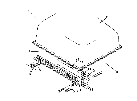
Fig. 1 is a perspective view of a typical
electrolytic cell of the present invention.

204406
3
Fig. 2 is a side elevation, in section, of the
cathode sidewall of Fig. 1.
Fig. 3 is an exploded, perspective view of a
portion of the sidewall busbar of the cell of Fig. 1.,
more particularly detailing, in partial section,
electrical and coolant connections.
Description of the Preferred Embodiments
The invention relates generally to electrolytic
cells suited for the electrolysis of aqueous alkali
metal chloride solutions. The cells may be used for the
production of chlorine, chlorates, chlorites,
hydrochloric acid, caustic, rydrogen and related
chemicals. For the sidewall ~f the cathode-walled
enclosure it has been typical to use a conductive metal
which has desirable strength and structural properties.
Most always, the wall will be made of steel, e.g., cold-
rolled, low carbon steel. For the cathode busbar
structure the useful metals are those which are highly
electrically conductive. Most always this metal will be
copper, but there may also be used aluminum.
Referring now more particularly to Fig. 1, a cell
shown generally at 1 has a cover 2 and four sidewalls 3.
The sidewall 3 in the foreground is positioned behind a
sidewall busbar 4. The sidewall busbar 4 is connected
by intercell connectors 5, only some of which are shown,
to an adjacent cell, not shown. More particularly, each
intercell connector 5 is connected to a spacer 7 which
is fitted over a post 8. The connector 5 on the one end
is secured to the post 8, and on the opposite end is
secured by nuts ~ to the base of an adjacent cell, not
shown.
These intercell connectors 5 are positioned across
almost the complete length of the sidewall busbar 4, at
the bottom. As is more particularly depicted in the
figure, this sidewall busbar ~ can be a unitary,

~0440~~
4
monolithic and planar busbar 4 that is, for the
particular cell 1 of the figure, as high as the cell
sidewall 3 and can be longer than the sidewall 3 to
which it is bonded. The busbar 4 may thus be actually
larger than the sidewall 3. But, in essence, the
sidewall busbar 4 and its adjacent sidewall 3 together
form one wall of the cell 1. The extra length of the
sidewall busbar 4, extending beyond the intercell
connectors 5, forms a sidewall busbar extension 11. To
this sidewall busbar extension 11 there are attached
cathode jumper switches or connectors 12. Each jumper
connector 12 comprises a tubular conduit 13 and a lug 14
extending into connection with the sidewall busbar 4 at
the sidewall busbar extension 11. Further, this
sidewall busbar 4 contains a cooling conduit passageway
15, extending in a generally loop configuration and
shown in phantom.
Referring then to Fig. 2, there is shown the
interface bonded structure of sidewall 3 and sidewall
busbar 4. This bonded structure extends the full length
from an edge of the cell cover 2 downwardly to a cell
bottom 16. Connecting to the sidewall 3 and sidewall
busbar 4 through a post 8 and spacer 7 is an intercell
connector, not shown. Extending into the sidewall
busbar 4 is a cooling conduit 15, the direction of the
flow of coolant to and from the conduit 15 being shown
by the arrows.
Referring then to Fig. 3, a sidewall busbar
extension 11 extends beyond a busbar 4. Connecting to
this sidewall busbar extension 11 are the cathode jumper
connector lugs 14. As shown more particularly in this
figure, a pair of jumper connector lugs 14 are secured
to the sidewall busbar extension 11 by a nut 17 and bolt
18 which connect through an aperture 22 in the sidewall
extension 11. There is then formed in the busbar 4 and
sidewall busbar extension 11 a conduit passageway 15,
generally concentric in cross section. Fluid cooling

~o~~o~~
media, usually water, can be fed into this conduit
passageway 15 by a coolant inlet feeder hose 20. After
circulating in the busbar 4 and extension 11, coolant in
the passageway 15 can flow out of the sidewall extension
5 11 through a coolant exit return hose 21. Cooling fluid
can be supplied to the inlet feeder hose 20 from a cell
room source, not shown, external to the cell.
By such means cooling fluid can be provided to the
cathode busbar 4 when an adjacent electrolytic cell is
jumpered, It is to be understood however that cooling
means can be used during routine cell operation to cool
the cathode busbar 4, although it is normally needed
only during jumpering of the cell when the entire
electrical current flows through the lugs 4 and busbar
extension 11 to the cathode busbar 4.
In assembly, the cathode busbar 4, being typically
a copper busbar 4, can be interface bonded to the
cathode sidewall 3 such as by explosion bonding, brazing
or roll bonding. Where the cathode busbar 4 is copper
and the cathode sidewall 3 is steel it is preferred to
use explosion bonding or brazing. Even though the
sidewall busbar 4 can be a unitary, monolithic planar
busbar 4, which even extends in length beyond the length
of the sidewall 3 and which is usually of uniform
thickness for its total length including the length
beyond the sidewall 3, such busbar 9 can nevertheless be
desirably interface bonded to the sidewall 3. Such
bonding can provide for an integral electrical unit
achieving desirable efficiency of cathode operation. It
is also to be understood that the busbar extension 11
may be an attachment to the sidewall busbar 4. Such
attachment can be by metallurgical means, e.g., welding,
or by mechanical means such as bolting.
It is to be.understood that the intercell
connectors 5 including the spacers 7, and posts 8, will
be made of any material of construction usually utilized
for such items, e.g., copper. Furthermore, the cathode

2044Q~~
6
jumper connectors 12 will have electrically insulating
tubular conduits 13, as well as lugs 14 as
conventionally employed for such electrolytic cells,
e.g., copper lugs 14. For cooling, the sidewall busbar
cooling conduit passageway 15 may take any desired form
for supplying cooling to the sidewall busbar 4. Usually
such passageway 15 will be fashioned in the form of a
loop originating in and exiting from, the sidewall
busbar extension 11. Where the supply of cooling liquid
is to be particularly utilized during jumpering, such a
loop may extend partly, e.g., substantially halfway,
along the length of the sidewall busbar 4, as more
particularly depicted in Fig. 1. In any event, for most
efficient cooling of the sidewall busbar 4 it is always
contemplated that cooling fluid will be provided to and
removed from the busbar 4 in the manner as shown in Fig.
3. This sidewall busbar passageway 15 is preferably
obtained by rifle drilling, i.e., deep and narrow
passage drilling performed with a lathe.

Representative Drawing
A single figure which represents the drawing illustrating the invention.
Administrative Status

2024-08-01:As part of the Next Generation Patents (NGP) transition, the Canadian Patents Database (CPD) now contains a more detailed Event History, which replicates the Event Log of our new back-office solution.

Please note that "Inactive:" events refers to events no longer in use in our new back-office solution.

For a clearer understanding of the status of the application/patent presented on this page, the site Disclaimer , as well as the definitions for Patent , Event History , Maintenance Fee  and Payment History  should be consulted.

Event History

Description Date
Time Limit for Reversal Expired 2009-06-08
Letter Sent 2008-06-06
Letter Sent 2005-11-23
Letter Sent 2005-01-24
Inactive: Office letter 2004-05-11
Inactive: Multiple transfers 2004-04-21
Inactive: Office letter 2003-07-22
Grant by Issuance 2000-07-18
Inactive: Cover page published 2000-07-17
Letter Sent 2000-05-08
Pre-grant 2000-04-07
Inactive: Final fee received 2000-04-07
Inactive: Single transfer 2000-04-07
Notice of Allowance is Issued 1999-11-12
Letter Sent 1999-11-12
Notice of Allowance is Issued 1999-11-12
Inactive: Status info is complete as of Log entry date 1999-11-05
Inactive: Application prosecuted on TS as of Log entry date 1999-11-05
Inactive: Approved for allowance (AFA) 1999-10-26
Application Published (Open to Public Inspection) 1992-01-14
Request for Examination Requirements Determined Compliant 1991-06-06
All Requirements for Examination Determined Compliant 1991-06-06

Abandonment History

There is no abandonment history.

Maintenance Fee

The last payment was received on 2000-03-15

Note : If the full payment has not been received on or before the date indicated, a further fee may be required which may be one of the following

  • the reinstatement fee;
  • the late payment fee; or
  • additional fee to reverse deemed expiry.

Patent fees are adjusted on the 1st of January every year. The amounts above are the current amounts if received by December 31 of the current year.
Please refer to the CIPO Patent Fees web page to see all current fee amounts.

Owners on Record

Note: Records showing the ownership history in alphabetical order.

Current Owners on Record
ELTECH SYSTEMS CORPORATION
Past Owners on Record
JAMES W. PYLE
L. CALVERT CURLIN
RICHARD L. ROMINE
ROBERT B. KUBINSKI
Past Owners that do not appear in the "Owners on Record" listing will appear in other documentation within the application.
Documents

To view selected files, please enter reCAPTCHA code :


To view images, click a link in the Document Description column. To download the documents, select one or more checkboxes in the first column and then click the "Download Selected in PDF format (Zip Archive)" or the "Download Selected as Single PDF" button.

List of published and non-published patent-specific documents on the CPD .

If you have any difficulty accessing content, you can call the Client Service Centre at 1-866-997-1936 or send them an e-mail at CIPO Client Service Centre.


Document
Description 
Date
(yyyy-mm-dd) 
Number of pages   Size of Image (KB) 
Representative drawing 1999-06-27 1 15
Representative drawing 2000-06-22 1 11
Description 1994-03-04 6 215
Claims 1994-03-04 5 128
Abstract 1994-03-04 1 18
Drawings 1994-03-04 2 38
Claims 1999-10-26 4 161
Commissioner's Notice - Application Found Allowable 1999-11-11 1 164
Courtesy - Certificate of registration (related document(s)) 2000-05-07 1 113
Maintenance Fee Notice 2008-07-20 1 171
Correspondence 2003-07-21 1 21
Correspondence 2000-04-06 1 40
Fees 2001-04-03 1 29
Fees 1996-03-11 1 59
Fees 1997-03-19 1 64
Fees 1995-03-12 1 58
Fees 1993-02-16 1 45
Fees 1994-03-23 1 52
Examiner Requisition 1995-03-29 2 99
Examiner Requisition 1997-01-23 4 191
Examiner Requisition 1993-04-18 2 88
Examiner Requisition 1999-07-14 2 94
Prosecution correspondence 1993-08-18 4 120
Prosecution correspondence 1995-06-27 3 170
Prosecution correspondence 1997-07-22 3 118
Prosecution correspondence 1999-10-13 2 60
Courtesy - Office Letter 1992-01-02 1 34