Sélection de la langue

Search

Sommaire du brevet 2044056 

Énoncé de désistement de responsabilité concernant l'information provenant de tiers

Une partie des informations de ce site Web a été fournie par des sources externes. Le gouvernement du Canada n'assume aucune responsabilité concernant la précision, l'actualité ou la fiabilité des informations fournies par les sources externes. Les utilisateurs qui désirent employer cette information devraient consulter directement la source des informations. Le contenu fourni par les sources externes n'est pas assujetti aux exigences sur les langues officielles, la protection des renseignements personnels et l'accessibilité.

Disponibilité de l'Abrégé et des Revendications

L'apparition de différences dans le texte et l'image des Revendications et de l'Abrégé dépend du moment auquel le document est publié. Les textes des Revendications et de l'Abrégé sont affichés :

  • lorsque la demande peut être examinée par le public;
  • lorsque le brevet est émis (délivrance).
(12) Brevet: (11) CA 2044056
(54) Titre français: BARRE OMNIBUS LIEE A L'INTERFACE POUR CATHODE DE CELLULE A DIAPHRAGME
(54) Titre anglais: BONDED BUSBAR FOR DIAPHRAGM CELL CATHODE
Statut: Périmé et au-delà du délai pour l’annulation
Données bibliographiques
(51) Classification internationale des brevets (CIB):
(72) Inventeurs :
  • ROMINE, RICHARD L. (Etats-Unis d'Amérique)
  • KUBINSKI, ROBERT B. (Etats-Unis d'Amérique)
  • CURLIN, L. CALVERT (Etats-Unis d'Amérique)
  • PYLE, JAMES W. (Etats-Unis d'Amérique)
(73) Titulaires :
  • ELTECH SYSTEMS CORPORATION
(71) Demandeurs :
  • ELTECH SYSTEMS CORPORATION (Etats-Unis d'Amérique)
(74) Agent: GOWLING WLG (CANADA) LLP
(74) Co-agent:
(45) Délivré: 2000-07-18
(22) Date de dépôt: 1991-06-06
(41) Mise à la disponibilité du public: 1992-01-14
Requête d'examen: 1991-06-06
Licence disponible: S.O.
Cédé au domaine public: S.O.
(25) Langue des documents déposés: Anglais

Traité de coopération en matière de brevets (PCT): Non

(30) Données de priorité de la demande:
Numéro de la demande Pays / territoire Date
552,731 (Etats-Unis d'Amérique) 1990-07-13

Abrégés

Abrégé anglais


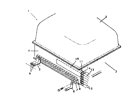
In a sidewall-enclosed electrolytic cell, such as
for the electrolysis of brine to form chloralkali
product, the cell can have at least one cathode
sidewall. There is now provided an at least
substantially wall-sized, planar busbar that is
interface bonded to the cathode sidewall. The interface
bonded, wall-sized busbar plus sidewall thereby at least
substantially serve as a wall unit for the electrolytic
cell. The wall-sized busbar has at least one internal
passageway therethrough for the circulation of cooling
fluid. Where the bonded busbar is connected by a jumper
switch for current connection, the cooling passageway of
the busbar may connect at the location of the jumper
switch.

Revendications

Note : Les revendications sont présentées dans la langue officielle dans laquelle elles ont été soumises.


-7-
THE EMBODIMENTS OF THE INVENTION IN WHICH AN EXCLUSIVE
PROPERTY OR PRIVILEGE IS CLAIMED ARE DEFINED AS FOLLOWS:
1. In an electrolytic cell wherein the cell comprises
a walled enclosure with there being at least one cathode
sidewall for said enclosure, said cell having a cover over,
and a cell bottom beneath, said walled enclosure, and with
there being means for introducing current from outside the
cell to said at least one cathode sidewall through a
busbar, the improvement comprising a cathode busbar structure
external to said cell, which structure has a unitary,
wall-sized sidewall busbar, which unitary and wall-sized
sidewall busbar is interface bonded to said at least one
cathode sidewall, whereby said at least one cathode
sidewall plus interface bonded sidewall busbar combine
together to form a wall unit for said cell, with said
sidewall busbar having at least one internal passageway
for the circulation of cooling fluid therethrough.
2. The cell of claim 1, wherein said at least one
cathode sidewall is a steel sidewall and said sidewall busbar
is a copper or aluminum busbar.
3. The cell of claim 1, wherein said sidewall busbar
is a planar busbar which is interface bonded to said at least
one cathode sidewall by explosion bonding, brazing, or roll
bonding.
4. The cell of claim 1, wherein the sidewall busbar is
connected to at least one jumper switch, and with an
impressed current being supplied through said at least one
jumper switch to said busbar.
5. The cell of claim 4, wherein said sidewall busbar
is a unitary, monolithic sidewall busbar.

6. The cell of claim 4, wherein said sidewall busbar
has a busbar extension member secured thereto and extending
beyond the length of said at least one cathode sidewall.
7. The cell of claim 4, wherein said sidewall
busbar has at least one rifle drilled cooling fluid
passageway.
8. The cell of claim 7, wherein said at least one
rifle drilled cooling fluid passageway in said busbar
extends beyond the length of said at least one cathode
sidewall.
9. The cell of claim 7, wherein said at least one
rifle drilled cooling fluid passageway extends one-half
the length of said busbar from said at least one jumper
switch.
10. The cell of claim 1, wherein said sidewall busbar
is connected by means of a spacer member to at least one
intercell connector.
11. A busbar for interface bonding to a cathode
sidewall of an electrolytic diaphragm cell, which
electrolytic cell can be utilized for brine electrolysis,
which busbar is interface bonded to said cathode sidewall and
comprises a planar metal busbar sized to the
size of said sidewall, or larger than said cathode sidewall,
said busbar being of a metal that can be interface bonded to
said cathode sidewall, with said busbar having at least one
internal passageway for the circulation of cooling fluid
therethrough.
12. The busbar of claim 11, wherein said cathode
sidewall is a steel sidewall and said busbar is a copper
busbar of uniform thickness.

-9-
13. The busbar of claim 11, wherein said internal
passageway of said busbar is a cooling fluid passageway
that is a rifle drilled passageway.
14. The busbar of claim 11, wherein said sidewall
busbar is larger than said cathode sidewall by extending
beyond the length of said sidewall defining a sidewall
extension portion, with the side wall extension portion
connecting to at least one jumper switch, and with an
impressed current being supplied through said at least one
jumper switch to said busbar.
15. The busbar of claim 14, wherein said sidewall
busbar is a unitary, monolithic sidewall busbar.
16. The busbar of claim 11, wherein said sidewall
busbar is a wall-sized busbar having a busbar extension
member secured thereto extending beyond the length of
said sidewall.
17. The busbar of claim 14, wherein said at least
one internal passageway through said busbar extends
beyond the length of said sidewall.
18. The cell of claim 17, wherein said at least
one internal passageway extends one-half the length of
said busbar from said at least one jumper switch.
19. In an electrolytic cell wherein the cell comprises
a walled enclosure with there being at least one cathode
sidewall for said enclosure, said cell having a cover over,
and a cell bottom beneath, said walled enclosure, and with
there being means for introducing current from outside the
cell to said at least one cathode sidewall through a
sidewall busbar which extends along and beyond said at least
one cathode sidewall, the improvement comprising at
least one dumper switch connected to said sidewall busbar at

-10-
the extension of said busbar beyond said at least one
sidewall, at least one internal passageway within said
sidewall busbar and extending through said sidewall busbar
extension for the circulation of cooling fluid therethrough,
and cooling fluid connection means connecting at said
sidewall busbar extension to said at least one cooling fluid
passageway.
20. The cell of claim 19, wherein said sidewall busbar
is a planar busbar which is interface bonded to said at least
one cathode sidewall.
21. The cell of claim 19, wherein an impressed current
is supplied through said at least one jumper switch to said
busbar.
22. The cell of claim 19, wherein said sidewall busbar
is a unitary, monolithic sidewall busbar which extends beyond
the length of said at least one cathode sidewall.
23. The cell of claim 19, wherein said sidewall busbar
is a wall-sized busbar and said busbar
extension is a busbar member secured thereto.
24. The cell of claim 19, wherein said at least
one internal passageway of said sidewall busbar is a
rifle drilled cooling fluid passageway.
25. The cell of claim 19, wherein said at least one
cooling fluid passageway in said busbar extends one-half the
length of said busbar from said at least one jumper switch.
26. The cell of claim 19, wherein said sidewall busbar
is connected by means of a spacer member to at least one
intercell connector.

Description

Note : Les descriptions sont présentées dans la langue officielle dans laquelle elles ont été soumises.


~04~O~G
BONDED BUSBAR FOR DIAPHRAGM CELL CATHODE
Background of the Invention
In the manufacture of chlor-alkali diaphragm cells,
there have been developed cells which operate at high
current capacities with correspondingly high production
capacities. Typically, chlo~-alkali diaphragm cells may
now operate at current capacities of upwards to about
200,000 amperes, while maintaining desirable operating
efficiencies. One such cell which has been developed
for this more efficient operation comprises a novel
cathode bulbar structure. As shown in the U.S. Patents
Nos. 3,859,196 and 3,904,504 this novel cathode bulbar
structure comprises at least one lead-in busbar and a
plurality of bulbar strips which have different relative
dimensions. This structure is attached to d sidewall of
the cell whereby the sidewall plus bulbar structure
provides an at least partially cathode--walled enclosure.
Such chlor-alkali diaphragm cells which have been
developed to operate at high current capacities can also
require a high amperage swi_ch apparatus. A suitable
such apparatus has been disclosed in U.S. Patent No.
3,778,680. Therein there is shown a switch apparatus
particularly for high amperage electrical switching,
which apparatus is resiliently mounted and has fluid-
cooled terminals.
It would be desirable to combine the features of

2044056
2
these developments to readily accommodate high amperage
switch apparatus with a cathode busbar structure of a
cathode-walled enclosure.
Summary of the Invention
It has now been found possible to provide a most
efficient cathode sidewall bulbar structure. The
structure is economically monolithic and unitary. The
structure can be desirably compatible with present day
high amperage switch apparatus. Such compatibility
includes linkage of the switch apparatus cooling means
with cooling means for the sidewall bulbar.
In one broad aspect the invention relates to an
electrolytic cell wherein the cell comprises a walled
enclosure with there being at least one cathode sidewall
for the enclosure, such cell having a cover over, and a
cell bottom beneath, the walled enclosure, and with
there being means for introducing current from outside
the cell to a cathode sidewall through a bulbar. In
this context, the invention provides the improvement
comprising a cathode busbar structure external to the
cell, which structure has an at least substantially
wall-sized sidewall busbar that is interface bonded to
the cathode sidewall, whereby the cathode sidewall plus
interface bonded sidewall busbar combine together to
form at least substantially a wall unit for such cell,
with the sidewall bulbar having internal passageways for
the circulation of cooling fluid therethrough.
In another aspect the invention is directed to a
novel busbar for interface bonding to a cathode sidewall
of an electrolytic diaphragm cell.
Brief Description of the Drawings
Fig. 1 is a perspective view of a typical
electrolytic cell of the present invention.

204406
3
Fig. 2 is a side elevation, in section, of the
cathode sidewall of Fig. 1.
Fig. 3 is an exploded, perspective view of a
portion of the sidewall busbar of the cell of Fig. 1.,
more particularly detailing, in partial section,
electrical and coolant connections.
Description of the Preferred Embodiments
The invention relates generally to electrolytic
cells suited for the electrolysis of aqueous alkali
metal chloride solutions. The cells may be used for the
production of chlorine, chlorates, chlorites,
hydrochloric acid, caustic, rydrogen and related
chemicals. For the sidewall ~f the cathode-walled
enclosure it has been typical to use a conductive metal
which has desirable strength and structural properties.
Most always, the wall will be made of steel, e.g., cold-
rolled, low carbon steel. For the cathode busbar
structure the useful metals are those which are highly
electrically conductive. Most always this metal will be
copper, but there may also be used aluminum.
Referring now more particularly to Fig. 1, a cell
shown generally at 1 has a cover 2 and four sidewalls 3.
The sidewall 3 in the foreground is positioned behind a
sidewall busbar 4. The sidewall busbar 4 is connected
by intercell connectors 5, only some of which are shown,
to an adjacent cell, not shown. More particularly, each
intercell connector 5 is connected to a spacer 7 which
is fitted over a post 8. The connector 5 on the one end
is secured to the post 8, and on the opposite end is
secured by nuts ~ to the base of an adjacent cell, not
shown.
These intercell connectors 5 are positioned across
almost the complete length of the sidewall busbar 4, at
the bottom. As is more particularly depicted in the
figure, this sidewall busbar ~ can be a unitary,

~0440~~
4
monolithic and planar busbar 4 that is, for the
particular cell 1 of the figure, as high as the cell
sidewall 3 and can be longer than the sidewall 3 to
which it is bonded. The busbar 4 may thus be actually
larger than the sidewall 3. But, in essence, the
sidewall busbar 4 and its adjacent sidewall 3 together
form one wall of the cell 1. The extra length of the
sidewall busbar 4, extending beyond the intercell
connectors 5, forms a sidewall busbar extension 11. To
this sidewall busbar extension 11 there are attached
cathode jumper switches or connectors 12. Each jumper
connector 12 comprises a tubular conduit 13 and a lug 14
extending into connection with the sidewall busbar 4 at
the sidewall busbar extension 11. Further, this
sidewall busbar 4 contains a cooling conduit passageway
15, extending in a generally loop configuration and
shown in phantom.
Referring then to Fig. 2, there is shown the
interface bonded structure of sidewall 3 and sidewall
busbar 4. This bonded structure extends the full length
from an edge of the cell cover 2 downwardly to a cell
bottom 16. Connecting to the sidewall 3 and sidewall
busbar 4 through a post 8 and spacer 7 is an intercell
connector, not shown. Extending into the sidewall
busbar 4 is a cooling conduit 15, the direction of the
flow of coolant to and from the conduit 15 being shown
by the arrows.
Referring then to Fig. 3, a sidewall busbar
extension 11 extends beyond a busbar 4. Connecting to
this sidewall busbar extension 11 are the cathode jumper
connector lugs 14. As shown more particularly in this
figure, a pair of jumper connector lugs 14 are secured
to the sidewall busbar extension 11 by a nut 17 and bolt
18 which connect through an aperture 22 in the sidewall
extension 11. There is then formed in the busbar 4 and
sidewall busbar extension 11 a conduit passageway 15,
generally concentric in cross section. Fluid cooling

~o~~o~~
media, usually water, can be fed into this conduit
passageway 15 by a coolant inlet feeder hose 20. After
circulating in the busbar 4 and extension 11, coolant in
the passageway 15 can flow out of the sidewall extension
5 11 through a coolant exit return hose 21. Cooling fluid
can be supplied to the inlet feeder hose 20 from a cell
room source, not shown, external to the cell.
By such means cooling fluid can be provided to the
cathode busbar 4 when an adjacent electrolytic cell is
jumpered, It is to be understood however that cooling
means can be used during routine cell operation to cool
the cathode busbar 4, although it is normally needed
only during jumpering of the cell when the entire
electrical current flows through the lugs 4 and busbar
extension 11 to the cathode busbar 4.
In assembly, the cathode busbar 4, being typically
a copper busbar 4, can be interface bonded to the
cathode sidewall 3 such as by explosion bonding, brazing
or roll bonding. Where the cathode busbar 4 is copper
and the cathode sidewall 3 is steel it is preferred to
use explosion bonding or brazing. Even though the
sidewall busbar 4 can be a unitary, monolithic planar
busbar 4, which even extends in length beyond the length
of the sidewall 3 and which is usually of uniform
thickness for its total length including the length
beyond the sidewall 3, such busbar 9 can nevertheless be
desirably interface bonded to the sidewall 3. Such
bonding can provide for an integral electrical unit
achieving desirable efficiency of cathode operation. It
is also to be understood that the busbar extension 11
may be an attachment to the sidewall busbar 4. Such
attachment can be by metallurgical means, e.g., welding,
or by mechanical means such as bolting.
It is to be.understood that the intercell
connectors 5 including the spacers 7, and posts 8, will
be made of any material of construction usually utilized
for such items, e.g., copper. Furthermore, the cathode

2044Q~~
6
jumper connectors 12 will have electrically insulating
tubular conduits 13, as well as lugs 14 as
conventionally employed for such electrolytic cells,
e.g., copper lugs 14. For cooling, the sidewall busbar
cooling conduit passageway 15 may take any desired form
for supplying cooling to the sidewall busbar 4. Usually
such passageway 15 will be fashioned in the form of a
loop originating in and exiting from, the sidewall
busbar extension 11. Where the supply of cooling liquid
is to be particularly utilized during jumpering, such a
loop may extend partly, e.g., substantially halfway,
along the length of the sidewall busbar 4, as more
particularly depicted in Fig. 1. In any event, for most
efficient cooling of the sidewall busbar 4 it is always
contemplated that cooling fluid will be provided to and
removed from the busbar 4 in the manner as shown in Fig.
3. This sidewall busbar passageway 15 is preferably
obtained by rifle drilling, i.e., deep and narrow
passage drilling performed with a lathe.

Dessin représentatif
Une figure unique qui représente un dessin illustrant l'invention.
États administratifs

2024-08-01 : Dans le cadre de la transition vers les Brevets de nouvelle génération (BNG), la base de données sur les brevets canadiens (BDBC) contient désormais un Historique d'événement plus détaillé, qui reproduit le Journal des événements de notre nouvelle solution interne.

Veuillez noter que les événements débutant par « Inactive : » se réfèrent à des événements qui ne sont plus utilisés dans notre nouvelle solution interne.

Pour une meilleure compréhension de l'état de la demande ou brevet qui figure sur cette page, la rubrique Mise en garde , et les descriptions de Brevet , Historique d'événement , Taxes périodiques et Historique des paiements devraient être consultées.

Historique d'événement

Description Date
Le délai pour l'annulation est expiré 2009-06-08
Lettre envoyée 2008-06-06
Lettre envoyée 2005-11-23
Lettre envoyée 2005-01-24
Inactive : Lettre officielle 2004-05-11
Inactive : Transferts multiples 2004-04-21
Inactive : Lettre officielle 2003-07-22
Accordé par délivrance 2000-07-18
Inactive : Page couverture publiée 2000-07-17
Lettre envoyée 2000-05-08
Préoctroi 2000-04-07
Inactive : Taxe finale reçue 2000-04-07
Inactive : Transfert individuel 2000-04-07
Un avis d'acceptation est envoyé 1999-11-12
Lettre envoyée 1999-11-12
Un avis d'acceptation est envoyé 1999-11-12
Inactive : Renseign. sur l'état - Complets dès date d'ent. journ. 1999-11-05
Inactive : Dem. traitée sur TS dès date d'ent. journal 1999-11-05
Inactive : Approuvée aux fins d'acceptation (AFA) 1999-10-26
Demande publiée (accessible au public) 1992-01-14
Exigences pour une requête d'examen - jugée conforme 1991-06-06
Toutes les exigences pour l'examen - jugée conforme 1991-06-06

Historique d'abandonnement

Il n'y a pas d'historique d'abandonnement

Taxes périodiques

Le dernier paiement a été reçu le 2000-03-15

Avis : Si le paiement en totalité n'a pas été reçu au plus tard à la date indiquée, une taxe supplémentaire peut être imposée, soit une des taxes suivantes :

  • taxe de rétablissement ;
  • taxe pour paiement en souffrance ; ou
  • taxe additionnelle pour le renversement d'une péremption réputée.

Veuillez vous référer à la page web des taxes sur les brevets de l'OPIC pour voir tous les montants actuels des taxes.

Historique des taxes

Type de taxes Anniversaire Échéance Date payée
TM (demande, 7e anniv.) - générale 07 1998-06-08 1998-03-24
TM (demande, 8e anniv.) - générale 08 1999-06-07 1999-02-16
TM (demande, 9e anniv.) - générale 09 2000-06-06 2000-03-15
Taxe finale - générale 2000-04-07
Enregistrement d'un document 2000-04-07
TM (brevet, 10e anniv.) - générale 2001-06-06 2001-04-04
TM (brevet, 11e anniv.) - générale 2002-06-06 2002-05-02
TM (brevet, 12e anniv.) - générale 2003-06-06 2003-05-02
Enregistrement d'un document 2003-05-27
TM (brevet, 13e anniv.) - générale 2004-06-07 2004-05-06
TM (brevet, 14e anniv.) - générale 2005-06-06 2005-05-09
Enregistrement d'un document 2005-09-09
TM (brevet, 15e anniv.) - générale 2006-06-06 2006-05-08
TM (brevet, 16e anniv.) - générale 2007-06-06 2007-05-07
Titulaires au dossier

Les titulaires actuels et antérieures au dossier sont affichés en ordre alphabétique.

Titulaires actuels au dossier
ELTECH SYSTEMS CORPORATION
Titulaires antérieures au dossier
JAMES W. PYLE
L. CALVERT CURLIN
RICHARD L. ROMINE
ROBERT B. KUBINSKI
Les propriétaires antérieurs qui ne figurent pas dans la liste des « Propriétaires au dossier » apparaîtront dans d'autres documents au dossier.
Documents

Pour visionner les fichiers sélectionnés, entrer le code reCAPTCHA :


Pour visualiser une image, cliquer sur un lien dans la colonne description du document. Pour télécharger l'image (les images), cliquer l'une ou plusieurs cases à cocher dans la première colonne et ensuite cliquer sur le bouton "Télécharger sélection en format PDF (archive Zip)" ou le bouton "Télécharger sélection (en un fichier PDF fusionné)".

Liste des documents de brevet publiés et non publiés sur la BDBC .

Si vous avez des difficultés à accéder au contenu, veuillez communiquer avec le Centre de services à la clientèle au 1-866-997-1936, ou envoyer un courriel au Centre de service à la clientèle de l'OPIC.


Description du
Document 
Date
(aaaa-mm-jj) 
Nombre de pages   Taille de l'image (Ko) 
Page couverture 2000-06-23 1 39
Dessin représentatif 1999-06-28 1 15
Dessin représentatif 2000-06-23 1 11
Description 1994-03-05 6 215
Revendications 1994-03-05 5 128
Abrégé 1994-03-05 1 18
Page couverture 1994-03-05 1 14
Dessins 1994-03-05 2 38
Revendications 1999-10-27 4 161
Avis du commissaire - Demande jugée acceptable 1999-11-12 1 164
Courtoisie - Certificat d'enregistrement (document(s) connexe(s)) 2000-05-08 1 113
Avis concernant la taxe de maintien 2008-07-21 1 171
Correspondance 2003-07-22 1 21
Correspondance 2000-04-07 1 40
Taxes 2001-04-04 1 29
Taxes 1996-03-12 1 59
Taxes 1997-03-20 1 64
Taxes 1995-03-13 1 58
Taxes 1993-02-17 1 45
Taxes 1994-03-24 1 52
Demande de l'examinateur 1995-03-30 2 99
Demande de l'examinateur 1997-01-24 4 191
Demande de l'examinateur 1993-04-19 2 88
Demande de l'examinateur 1999-07-15 2 94
Correspondance de la poursuite 1993-08-19 4 120
Correspondance de la poursuite 1995-06-28 3 170
Correspondance de la poursuite 1997-07-23 3 118
Correspondance de la poursuite 1999-10-14 2 60
Courtoisie - Lettre du bureau 1992-01-03 1 34