Note: Descriptions are shown in the official language in which they were submitted.
~~: ~: ~ ~'.'. 31
27837
Patent Application
for
SNAP-IN CONNECTOR
Field of 'the Invention
The invention relates to a connector for coupling an
electrical conduit to a support. More particularly, the
invention relates to a connector having a one-piece tubular
body member with a plurality of resilient legs with locking
tongues, external threads, and a receiving formation for
1~ receiving the electrical conduit; and a one-piece take-up
nut with an abutment surface and internal threads for
engagement with the external threads of the body member.
The connector clamps the support between the locking
tongues and the abutment surface.
gackctraund of the Invention
In building construction, utility signal lines are
typically encased by a protective sheath to avoid damage
from contact with other building components. Electrical
cables are generally covered with a flexible cladding or
conduit which carries a plurality of conductors throughout
the building between terminal connections or junction
boxes. The conductors are fed through an aperture in a
support or junction box, and the conduit is fastened to the
box to hold the conductors securely in place.
~~~ ! 3. /~ f 1 i ~ f'.
t. .. .t '~.~ ~; ',1
_ 2 _
In the past, threaded bushings or locking collars have
been used to retain the electrical conduit in a support.
Many of the connectors are secured in the aperture of the
support by threads, which requires extra installation time
to a7.ign and turn the connector in place. Other connectors
snap in place and retain the side walls of the aperture in
a preformed groove, which limits use of the connectors to
certain wall thicknesses. Many connectors also have an
excessive number of parts, for example, a bushing, a
washer, and a third clamping member, which complicate
installation and increase cost.
Examples of these prior connectors are disclosed in
the following patents: British Patent No. 13,936; German
Patent No. 300,546; and U.S. Patent Nos. 4,885,429 to
Schnittker; 3,814,467 to VanBuren, Jr.; 4,234,218 to
Rogers; 4,864,080 to Fochler et al; 4,248,131 to Larro;
4,578,528 to Borsh et al; 4,494,779 to Neff et al;
4,468,535 to Law; 4,141,477 to Hengesbach; 1,215,595 to
Weikert et al; 4,219,222 to Brusadin; 4,225,162 to Dola;
4,666,190 to Yamabe et al; 4,711,472 to Schnell; 4,299,363
to Datschefski; 3,993,333 to Biswas; 4,881,662 to Tallman;
4,621,166 to Neuroth; 4,641,863 to Shemtov; 4,012,578 to
Moran et a1;.4,880,387 to Stikeleather et al; and 3,154,281
to Frank.
Summar~t of the Invention
Accordingly, it is a primary object of the invention
to provide a durable connector capable of securely coupling
a flexible electrical conduit to a support.
Another object of the invention is to provide a
connector that can be installed quickly and easily.
Another object of the invention is to provide a
connector that accommodates various thicknesses of the
support, and thus provides versatility in application.
i ~
~ir~ =~i. ,'~~ r
:. t,'~ 1_!
- 3 -
A further object of the invention is to provide a
connector that is relatively inexpensive because it
requires only two parts.
The foregoing objects are basically attained by
providing a connector for coupling an electrical conduit to
a support having an aperture, the combination comprising a
one-piece tubular body member with first and second ends
having a plurality of resilient lags with radially
extending locking tongues thereon, the legs being located
at the first end and being adapted to extend through the
aperture, external threads disposed between the first and
second ends, and receiving means disposed on the second
end, for receiving the conduit therein; arid a one-piece,
tubular take-up nut with first and second ends having an
abutment surface disposed on the first end of the nut, and
internal threads disposed between the first and second ends
of the nut threadedly engaging the external threads on the
body member, whereby the locking tongues and the abutment
surface clamp opposing sides of the support adjacent the
aperture.
Other objects, advantages, and salient features of the
invention will become apparent from the following detailed
description, which, taken in conjunction with the annexed
drawings, discloses preferred embodiments of the invention.
D_rawinas
Referring now to the drawings which form part of this
original disclosure:
Fig. 1 is a side elevational view in longitudinal
section of the connector in accordance with the invention
with the electrical conduit inserted in the body member,
and the take-up nut about to be clamped on the support;
Fig. 2 is a side elevational view of the connector in
longitudinal section with the electrical conduit retained
;:3 i1 y ~ ~a
an ::.:ir~v..,!
- 4 -
within the body member and the support clamped between the
locking tongues and abutment surface of the nut;
Fig. 3 is an exploded side elevational view in
longitudinal section of the two garts of the connector and
electrical conduit as shown in Figs. Z and 2;
Fig. 4 is a side elevational view in longitudinal
section of the connector with liquidtight seals;
Fig. 5 is a side elevational view in longitudinal
section showing a slightly modified embodiment of the
connector in which the electrical conduit is retained
within the hollow body member;
Fig. 6 is an exploded side elevational view in
longitudinal section of the two-piece connector and
electrical conduit as shown in Fig. 5;
Figs. 7a and 7b are a side elevation and longitudinal
section of a modification of the body member shown in Figs.
1-3; and
Fig. 8 is an exploded view in longitudinal section of
further modifications of the body member and take-up nut as
shown in Fig. 3.
Detailed Description of the Invention
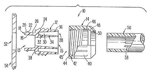
As seen in Figs. 1-3, electrical connector 10 in
accordance with the invention comprises a one-piece tubular
body member 12 threadedly coupled with a take-up nut 14 to
couple conduit 56 to support 54. The body member 12 and
take-up nut 14 may be made of any conventional material
such as plastic or metal, but are preferably made of
polyvinylchloride (FVC) or nylon.
Tubular body member 12 is integrally formed from one
piece of material, such as plastic, and is hollow with two
opposed open ends, first end 13 and second end 15, and a
longitudinal axis running therethrough. A plurality of
resilient legs 16, preferably two, extend from first end
.nd ,~~4 .~~ i .
:r 9.,
Goo f. ~.~ -: , ~~ i.i
- 5 -
13. Each resilient leg 16 has an axially extending lacking
tongue 18 with a radially inwardly tapered sliding face 20
and a radially extending locking shoulder 22. Between the
ends of the ',.ubular body member 12, there are external
threads 24 spaced from locking shoulders 22 of locking
tongues 18 by a generally cylindrical intermediate region
26 which may taper inwardly. The second end 15 of body
member 12 has a receiving formation 28 formed as an annular
recess 30 with radially inwardly and outwardly tapered
lp resilient walls. Recess 30 has an annular bottom wall 32,
a radial~.y outwardly tapered inside wall 34 and a radially
inwardly tapering outside wall 36. Receiving formation 28
also provides an annular radially extending stop shoulder
38 located between external threads 24 and intermediate
region 26.
Take-up next 14 is a one-piece, tubular member
integrally formed of plastic, for example, and has exterior
gripping ridges 40 to facilitate turning. IVut 14 has
internal threads 42 located between a first open end 45
having an annular, radially extending abutment surface 44
and a second open end 50. A cylindrical intermediate
region 46 spaces internal threads 42 from second end 50 and
is connected to second end 50 by an angled, preferably
radially inwardly tapering frustoconical, surface 48.
In operation, body member 12 is snapped into a
preferably circular aperture 52 in support 54, such as a
junction box. Resilient Iegs l6 are pressed against the
sides of aperture 52 which allows tapered sliding face 20
to slide into aperture 52 and snap in place by being
' 30 retained by locking shoulders 22. The intermediate region
26, defined between locking shoulders 22 and stop shoulder
38, accommodates various thicknesses of support 54, as
clearly shown in Fig. 1. Once body member 12 is retained
in, aperture 52, take-up nut 14 is partially threaded onto
<v~yj°~~ ;,
-- I ~ ,1
- 6 -
second end 15 of body member 12 by engaging internal
threads 42 with external threads 24. Electrical conduit 56
is then moved into receiving formation 28. Conventional
flexible sheath or conduit material, such as PVC, encases
conductors 58 which will ultimately extend through aperture
52 in support 54.
The conduit 56 is shown as a smooth-walled tube, but
it is contemplated that recess 30 in receiving formation 28
can accommodate any conventionally configured sheath.
Thus, conduit 56 is moved into receiving formation 28 and
is received in recess 30 between inside wall 34 and outside
wall 36. Once conduit 56 is in place in recess 30, take-up
nut 14 is completely screwed Onto body member. 12. As shown
in Fig. 2, take-up nut 14 travels along the longitudinal
axis of body member 12 toward support 54 and locking
shoulders 22. The exterior diameter of the second end 15
of the body member 12 is less than the interior diameter of
intermediate region 46 of take-up nut 14, but greater than
the interior diameter of second end 50 of take--up nut 14.
Thus, as nut 14 moves along body member 12, outside wall 36
of receiving formation 28 abuts angled surface 48 at the
second end 50 of take-up nut 14. Angled surface 48 acts to
squeeze resilient walls 34 and 36 of recess 30 to fit
within the second end 50 of take-up nut 14. The squeezing
action clamps conduit 56 between walls 34 and 36 in recess
and provides a secure friction interlock between conduit
56 and body member 12. Take-up nut l4 is ratated along
body member 12, until abutment surface 44 reaches and abuts
support 54, thus clamping support 54 between locking
' 30
shoulders 22 and abutment surface 44.
zt can be seen in Figs. 1 and 2 that various
thicknesses of support 54 will be accommodated between
locking shoulders 22 and abutment surface 44, and that the
connector may be adjusted for different supports by merely
,'A h~.' ;'.~~' f % t '
'° v '.~,' .,i', t1 si ~_,I
7 -
rotating take-up nut 14 along body member 12. Thus, the
engagement of external threads 24 of body member 12 and the
internal threads 42 of take--up nut 14 provides two
functions, one being the clamping action of abutment
surface 44 and locking shoulders 22, and the other being
the squeezing action of inside wall 34 and outside wall 36
by the second end 50 of take-up nut 14. The threading
action of take-up nut 14, therefore, serves to clamp body
member 12 to support 54 and to conduit 56.
To achieve a liquidtight connection for the electrical
conduit, means for sealing is provided. As seen in Fig. 4,
which represents the connector elements described with
refgrence to Figs. 1-3, an elastomer gland or sealing ring
60 is provided around intermediate region 26 and adjacent
stop shoulder 38 of body member 12. An additional sealing
ring 62 is also provided around body member 12 on outside
wall 36 of receiving formation 28. Sealing ring 60
effectuates a seal between body member 12 and support 54.
Sealing ring 62 effectuates a seal between outside wall 36
of body member 12 and intermediate region 46 of take-up nut
14. The seals prevent leakage at the connection between
electrical conduit 56 and junction box 54.
Embodiment of Fias. 5-6
Figs. 5 and 6 show a modification of the connector
which includes hollow body member 64, take-up nut 84, and
conduit 98, coaxially aligned about a longitudinal axis
with aperture 52 in a support 54, such as junction box.
Body member 64 has resilient legs 66 with a plurality
of locking tongues 68, each having a radially inwardly
tapered sliding face 70 and a radially extending locking
shoulder 72 extending from first open end 65. External
threads 74 are spaced from locking shoulders 72 by a
cylindrical intermediate region 76. Receiving formation 78
~~ ~i i
_ 8 -
comprises internal spiral grooves 80 and an annular stop
ledge 82, with an exterior cylindrical surface 83 extending
from threads 74 to second open end 79 of body member 64.
Take-up nut 84 is similar to nut 14 shown in Figs. 1
3. Nut 84 has exterior gripping ridges 86 and interior
threads 88 with an annular, radially extending abutment
surface 90 on open first end 87. znternal threads 88 are
spaced from the second end 96 by a cylindrical intermediate
region 92. Intermediate region 92 is connected to open
second end 96 of nut 84 by an angled, preferably
frustoconical, surface 94.
In operation, the embodiment of Fig. 5 functions
similarly to the embodiment of Fig. 1. Take-up nut 84
screws onto body member 64, clamping support 54 between
locking shoulders 72 and abutment surface 90. Again,
intermediate region 76 accommodates various thicknesses of
support 54. Receiving formation 78 is modified to comprise
internal grooves 80 for receiving a flexible helical
electrical conduit 98. Conduit 98 carries a plurality of
electrical conductors 100, and is made of a flexible
material. The helical configuration adds to the
flexibility of the conduit.
The ridges of helical conduit 98 are retained in
internal grooves 80 of body member S4 as shown clearly in
Fig. 5. Conduit 98 is attached to body member 64 by
turning it within hollow member 64 to engage grooves 80.
Stop ledge 82 prevents the conduit from protruding into the
aperture 52 of support 54. In this case, conduit 98 may be
coupled to body member 64 either before ar after take-up
nut 84 is secured to body member 64, thus clamping support
54 between locking shoulders 72 and abutment surface 90.
Resilient legs 66 are snapped into aperture 52 xn the same
manner as the resilient legs 16 of the first embodiment are
snapped in place. As discussed, tapered sliding face 70
j~ ~~ i ~ ~'i #,
.~ , i.i i..'s
-
slides against the walls of aperture 52, allowing resilient
tongues 68 to slide through aperture 52 and be retained in
support 54 by locking shoulders 72. In this embodiment,
the exterior diameter of the second end ?9 of the body
member 12 is less than the interior diameter of
intermediate region 92 of take-up nut 84, but substantially
the same as the interior diameter of second end 96 of take-
up nut 84. The second end 96 of take-up nut 84 provides
lateral support to the clamped assembly. Seals 60 and 62,
described with respect to Fig. 4, can also he used in the
embodiment of Fig. 5 to effectuate a liquidtight
connection.
Embodiment of Fias. 7a-7b
Figs. 7a and 7b show a modified body member 112 which
is substantially the same as body member 12 shown in Figs.
1-3 with the addition of locking tabs 117 and 119~
Accordingly, the elements of body member 112 which are the
same as corresponding body member 12 will not be discussed
in detail.
Hollow body member 112, having resilient legs 116,
external threads 124, and receiving formation 128, has at
least two resilient elongate locking tabs 117 and 119 which
are integrally formed in radially inwardly tapering outside
wall 136 of annular recess 130. Locking tabs 117 and 119
are molded in body member 112 or cut from outside wall 136.
Tabs 117 and 119 have interiorly protruding pointed fingers
121 and 123, respectively. Longitudinally extending slits
129 form two opposed sides of each tab and extend from
fingers 121 and 123 into outside wall 136. Adjacent tabs
117 and 119 are generally rectangular slots 125 and 127,
rE'spectively.
Slits 129 allow 'tabs 117 and 119 to act as living
hinges. When a conduit is inserted into annular recess
-.
~j '' ~ ~~ f~ ~.
- to -
130, tabs 117 and 119 are deflected out of recess 130 into
slots 125 and 127. However, protruding fingers 121 and 123
still contact the inserted conduit, gripping the conduit
and pressing it against inside wall 134 of recess 130.
As discussed with respect to the connector of Figs. 1
3, the conduit may be smooth-walled or helically grooved.
In operation, a take-up nut, such as take-up nut 14 shown
in Fig. 3, is screwed over body member 112, and acts to
further press lacking 'tabs 117 and i19 against the inserted
conduit.
Embodiment of Fia. 8
Fig. 8 discloses an exploded view of a further
modification of the connector according to the invention.
Body member 212 is substantially the same as body member 12
of Figs. 1-3, except for the truncation of outside wall
236. Take-up nut 214 is also substantially the same as
take-up nut 14 shown in Figs. 1-3, with the addition of
interior conduit thread 249 in second end 250.
Accordingly, the elements of body member 212 and take-up
nut 214 previously described with respect to body member 12
and take-up nut 14 will not be discussed in detail.
Hollow body member 212 has resilient legs 216 for
insertion into aperture 52 in support 54, external threads
224 to receive take-up nut 214, and receiving formation 228
for securing conduit 98 thereto. Receiving formation 228
is an annular recess 230 having radially outwardly tapered
inside wall 234 and truncated radially inwardly tapered
outside wall 236.
Take-up nut 214, with internal threads 242 and
abutment surface 244, has an additional conduit thread 249
in second end 250. The diameter of thread 249 is smaller
than the diameter of threads 242, and the diameter of
second end 250 is smaller than the diameter of second end
c/-, 'q ~ ; .~ ~ ~'
- 11 -
50 in nut 14 shown in Figs. 1-3. Conduit thread 249
connects planar intermediate region 246 inside take-up nut
214 to constricted second end 250 and is adagted to
threadedly receive the helical sheath of conduit 98.
In operation, body member 212 is inserted into
aperture 52. Take-up nut 214 is threaded onto body member
212 by engaging internal threads 242 with external threads
224. Conduit 98 is threaded into second end 250 of take-up
nut 214 by engaging conduit thread 249 with the helical
wrap of conduit 98 at any point during assembly.
Ultimately, take-up nut 214 is screwed completely over body
member 212 until support 54 is clamped between locking
shoulders 222 of resilient legs 216 and abutment surface
244, and conduit 98 is threaded in take-up nut 214 and
received in recess 230 of receiving formation 228 in body
member 212. As can be understood by Fig. 8, truncated
outside wall 236 of body member 212 allows conduit thread
249 free access for engagement with the helical surface of
conduit 98, and inside wall 234 provides internal sugport
to conduit 98 for a secure interlock.
Sealing rings 60 and 62 shown in Fig. 4 may also be
utilized in the embodiments of Figs. 7a and 7b and Fig. 8
to effectuate a liquidtight joint.
While advantageous embodiments have been chosen to
illustrate the invention, it will be understood by those
skilled in the art that various changes and modifications
can be made therein without departing from the scope of the
invention as defined in the appended claims.