Note: Descriptions are shown in the official language in which they were submitted.
~ 2044403
- ~ ~= ACCELBRATOR PEDAL ~SSEMBLY
The present invention relates to accelerator pedal
assemblies, and more particularly to a floor pan
mounted electronic accelerator pedal assembly for
vehicles.
Until recent years, the conventional accelerator
pedal assembly was m~chAnical in nature in that the
position of the accelerator pedal was transferred by
m~c-h~n;cal means to the engine throttle control. This
mechAnical means is usually in the form of mec-h~nical
linkages and cables.
More recently, with the advent of fuel injection
and more sophisticated and precisely tuned fuel control
systems, electronic controls have come into popular use
rather than mech~nical controls. With this has been
the adaptation of the electronic accelerator pedal
assemblies which include an electronic device for
indicating the pedal position from its idle position to
the fully wide open throttle position. Typical of such
assemblies are those shown in U.S. Patent Nos.
4,335,689; 4,718,380; 4,727,838; 4,831,985; and
4,883,037.
However, while such systems may allow more precise
control of engine operating parameters, the electronic
componentry is more delicate than the predecessor
mech~nical components, and must be protected by changes
in the overall design concept for the accelerator pedal
assembly.
Specifically, the wiring to the electrical
components must be secure from the possibility of
chafing which will eventually result in electrical
failure. Thus, the pedal assemblies must not precipi-
tate any motion in the connecting wires themselves,
such as shown in the electronic pedal assembly of U.S.
Patent No. 4,883,037. Further, one must take care that
the electrical components of the assembly are placed
outside of the hostile environment zone lying between
the operator's foot or the accelerator pedal and the
- ~ - 2 2044403
floor pan of the vehicle. This zone is subjected to
the substances the operator may get on his or her shoes
such as gas, oil, salt, dirt, acid and the like.
Likewise, there is a need for a pedal assembly
designed as a single component which can be easily
installed in the vehicle as original equipment or as a
replacement for original equipment and one which is
itself serviceable in basic modules or component parts.
The present invention is designed to service the
above-mentioned needs.
The present invention contemplates an electronic
pedal assembly wherein the electrical components are
located outside of the hostile environment zone beneath
the accelerator pedal.
The invention further contemplates an electronic t
accelerator pedal assembly wherein the electrical
wiring ext~;ng between the electrical components on
the pedal assembly to the main wiring harness of the
vehicle are not caused to move relative to the vehicle
cab during pedal actuation.
The invention further contemplates an electronic
accelerator pedal assembly including means establishing
a relationship between the rotation of the accelerator
pedal and the voltage output of the electrical
component indicating pedal position, thereby providing
(i) a progressive pedal effort without any momentary
increases or decreases in voltage output; and (ii) an
assembly which will provide the same amount of fuel for
a given pedal input regardless of pedal position.
The invention also contemplates an accelerator
pedal assembly which can be installed as a preadjusted
complete unit involving minimum installation effort and
being completely compatible with or as a replacement
for existing pedal assemblies.
Further, the invention contemplates an accelerator
pedal assembly having a minimum number of distinctly
separate and serviceable units, whereby service work
..
1~ 2044403
~ = 3
can be performed quickly and conveniently on any one of
the units without disturbing the installation of the
remaining units.
Also, the invention contemplates providing the
accelerator pedal assembly with an optional pedal blade
which can interact with m~ch~n;cal components outside
of the vehicle cab. The motion of the blade can
operate, or be operated by, the same components as the
primary accelerator system.
Accordingly, in one aspect of the present
invention, there is provided a control pedal assembly
comprising a base bracket member; a housing portion
carried by the base bracket member at one end thereof;
a control pedal displaceably secured to the base
bracket member and adapted to move relative to the ba~e
bracket member within a range exten~;ng from a first
position to a second position; electronic means secured
to the housing portion for producing an electrically
generated output signal in proportion to the location
of the control pedal in any position from the first
position to the second position; the housing portion
and electronic means being supported by the base
bracket member in an elevated position located above
the upper extremities of the control pedal, whereby the
electronic means will be free of particulates or other
contaminants commonly carried by the control pedal or
otherwise transferred to the pedal assembly by the
operator.
The features and advantages of the present
invention will be readily apparent from the following
detailed description of the best mode for carrying out
the invention when taken in conjunction with the
accompanying drawings, wherein:
Figure 1 is a side elevation view of the
electronic accelerator pedal assembly in accordance
with the present invention;
`
2044403
~ 4
Figure 2 is a perspective view of the electronic
accelerator pedal assembly in accordance with the
present invention and showing the same at the idle
position;
Figure 3 is an exploded view of the top portion of
the accelerator pedal assembly in accordance with the
present invention;
Figure 4 is a sectional view taken substantially
along the lines 4-4 of Figure 2;
Figure 5 is a side elevation view of the top
portion of the accelerator pedal assembly illustrating
the actuation of the idle validation switch in
accordance with the present invention;
Figure 6 is a side elevation view of the
electronic accelerator pedal assembly in accordance
with an alternative embodiment of the present
invention;
Figure 7 is a plan view of Figure 6 showing in
partial cross-sectional view the potentiometer input
shaft as received within the potentiometer; and
Figure 8 is an exploded expanded view of the
potentiometer input shaft and the potentiometer socket
member within which it is received, as viewed generally
in the direction of lines 8-8 of Figure 7.
~' .
20~403
FMC 0228 PUS -5-
89-561
Best Mode For Carryinq out The Invention
The electronic accelerator pedal assembly
performs the accelerator control function for a vehi-
cle built with an onboard computer requiring pedal
position input. This input is used to operate elec-
tronically controlled engines, and in some cases,
transmisslons.
The assembly as seen in Figures 1 and 2 is
adapted to mount into the vehicle in place of an ex-
isting accelerator pedal or as original equipment. Tothe driver or operator, it will operate in the same
manner as any conventional accelerator pedal assembly,
having the same feel and basically functioning in the
same manner.
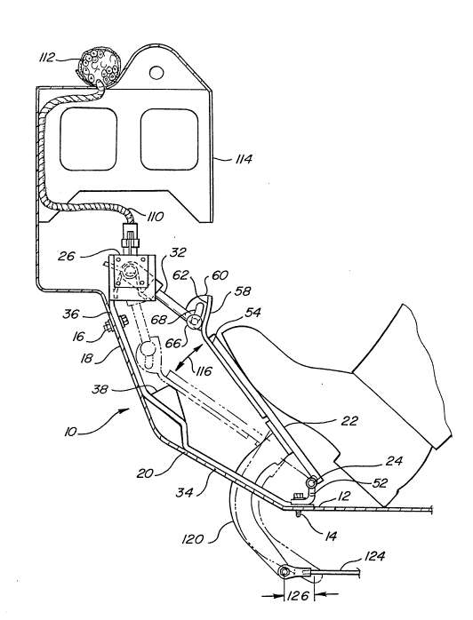
The general assembly of the accelerator
pedal assembly within a vehicle cab is best shown in
Figures 1 and 2. The accelerator pedal assembly,
generally designated 10, is adapted to be mounted to
the floor of the vehicle cab. The lower portion is
mounted to the floor pan 12 by several bolts 14.
Likewise, at its upper end, it is secured by several
bolts 16 to that part of the floor which is normally
referred to as the toe board 18.
The accelerator pedal assembly includes a
base bracket member 20, an accelerator pedal 22
hingedly connected by hinge pin 24 to the lower por-
tion of the base bracket member, an upper housing
portion 26 which is part of the base bracket member
and includes certain electrical components affixed
thereto including a potentiometer 28 and an idle vali-
dation switch 30, and an oscillating follower member
32 pivotally connected to the free end of the acceler-
2044403
FMC 0228 PUS -6-
89-561
ator pedal for translating the motion of the accelera-
tor pedal to the electrical components 28 and 30.
More specifically, it is seen that the base
bracket member 20 is in the form of an elongated plate
member. It includes a lower portion 34 which is gen-
erally horizontal to the floor pan 12, and an upper
portion 36 arranged generally vertically. At the mid-
point of the base bracket member 20, which is general-
ly at the juncture of the upper and lower portions
thereof, there is located a stop member 38 which proj-
ects upwardly in the direction of the accelerator
pedal 22 and acts as a stop for the a,ccelerator pedal
representing the wide-open-throttle position. At the
extreme upper end of the base bracket member, the
housing portion 26 is formed by two laterally spaced
and outwardly projecting walls 40 and 42. Each of the
walls include a flange 44,46, respectively, at the
free end thereof which is stepped at its lower portion
as seen best in Figure 3 to form a stop shoulder
48,50, respectively, described in detail below.
The accelerator pedal 22 includes a hinge 24
at its lower end allowing it to be fixed to a hinge
plate 52 which in turn is affixed to the base bracket
member by the same bolt 14 affixing the base bracket
member to the floor pan. On the underside of the
accelerator pedal, there is secured a flat plate mem-
ber 54 extending beyond the pedal portion of the ac-
celerator pedal and providing a coupling member 56 for
coupling the angular movement of the accelerator pedal
with that of oscillating follower member 32 which in
turn controls the position of the rotary input shaft
70 received within potentiometer 28.
The coupling member includes a laterally
extending plate portion 58 and a flange portion 60 ex-
` ~ 2044~03
FMC 0228 PUS -7-
89-561
tending therefrom in the direction of the base bracket
member 20. The laterally extending portion 58 is
curved generally along an axis parallel to that of
hinge pin 24. The concave underside thereof provides
a cam surface 62 upon which a cam follower in the form
of a roller 66 is adapted to ride. The flange 60
includes a generally curved slot 68 to allow a means
for fixing the follower 32 to the coupling.
Looking particularly at Figures 3, 4 and 5,
the housing portion 26 of the base bracket member is
adapted to retain a rotary potentiometer 28 on the
outboard side of one wall member 40 and an idle vali-
dation switch 30 on the outboard side of the other
wall 42. Each of the walls is bored along a lateral
axis to support a rotary input shaft 70 on bearings
80. Suitable means are provided on the shaft 70 for
keying it to the rotary input shaft of the rotary
potentiometer 28, and to the oscillating follower
member 32 and to an actuating lever 72 located in
proximity to the idle validation switch and adapted to
engage a trip lever 73 when in the idle position. For
this purpose, the rotary shaft can be flattened
throughout its length on a minor arc portion of its
circumference as shown at 74 in Figures 4 and 5. In
this way, the shaft is keyed to the follower member 32
and actuating lever 72, each of which includes a cor-
respondingly shaped slot 76 and 78, respectively.
Likewise, bearings 80 which support the input shaft on
walls 40,42 include an inner race member 82 having a
correspondingly shaped slot 84.
The manner in which the input shaft 70 is
keyed to the potentiometer 28 is explained below in
connection with Figures 7 and 8.
`` ~ 20~403
FMC 0228 PUS -8-
89-561
The oscillating follower member 32 is lo-
cated within the housing portion 26 and is supported
by and adapted to pivot about the rotary shaft 70.
The follower member includes a laterally extending
stop member 86.
As seen best in Figure 4, the follower mem-
ber 32 is adapted to be biased by a torsion coil spr-
ing 88 in a position shown in phantom line in Figure 4
which represents the idle position of the accelerator
pedal. The stop member 86 will abut at both walls
with stop shoulders 48,50 formed in flanges 44 and 46,
respectively. The preferred coil spring as seen in
~igure 2 is known as a "hairpin" spring. It includes
an intermediate portion 90 between respective coils
92,94 and ends 96,98. It functions as a dual spring.
If one-half should brea~, the remaining half provides
a back-up and continues to function. As seen, the
coil spring is adapted to bear against the housing
portion at intermediate portion 36 and against the
stop member 86 at its ends 96,98.
At its opposite end, the oscillating follow-
er member 32 includes a pin 100 having a roller 66
rotationally mounted thereon. The pin rides within an
arcuate slot 68 formed in the flange portion 60. It
is held within the slot by any suitable means such as
washer 106 and cotter pin 108 as shown.
As noted below, the securing of pin 100
within slot 68 also serves to preclude undesirable
spring back of the accelerator pedal 22 when the oper-
ator may abruptly release the pedal. Thus, the pedal
22 is restrained to traverse only the arc designated
116 in Figure 1 between the idle and wide open throt-
tle positions. At the same time, the roller 66 will
" ~ 2044403
FMC 022B PUS -9-
89-561
bear against the cam surface 62 of the accelerator
pedal member.
It will be noted that the rotary potentiome-
ter 28 is securely fixed to the housing portion 26.
Thus, regardless of the movement of the accelerator
pedal, the rotary potentiometer will remain fixed in
position. The wire 110 which transmits the electrical
output o~ the potentiometer to a control means (not
shown), will likewise remain in a fixed position.
Thus, the entire electrical wiring assembly from the
potentiometer 28 to the main wiring harness 112 within
the dash support structure 114 as seen in Figure 1
will remain in a stationary position and be free from
chafing and other conditions causing wear and prema-
ture failure.
As an optional feature, the acceleratorpedal can include a secondary pedal blade 120 fixed to
the underside of the accelerator pedal and extending
through a portion of the base bracket-member and the
floor pan at an opening 122 to a termin`al position
outside the vehicle cab. At its opposite end, the
secondary pedal blade can be affixed to a control rod
124. Upon actuation of the pedal from the idle posi-
tion as shown in solid line in Figure 1 to the wide-
open-throttle position as represented in phantom line
in Figure 1, the secondary pedal ~lade will translate
the control rod 124 over an axial travel path indi-
cated at 126. The control rod 124 as controlled by
the secondary pedal blade can either operate or be
operated by mechanism components outside the vehicle
cab, e.g., mechanically modulated automatic transmis-
sions.
In Figures 6-~, there is shown an alterna-
tive embodiment to the accelerator pedal assembly.
` 204~03
FMC 0228 PUS -10-
89-561
The accelerator pedal assembly 200 includes
the same basic components, namely, an accelerator
pedal 210, a base bracket member 212 having a housing
portion 214 with a rotary potentiometer 216 and idle
validation switch 218 mounted thereon, and a spring
biased follower member 220 rotatably supported on a
potentiometer input shaft 222 at one end and coupled
to the accelerator pedal 210 at its other end.
The accelerator pedal 210 has a single rub-
ber covered plate member 224 having a hinge 226 at its
lower end and a coupling member 228 at its upper end.
Laterally extending plate portion 230 includes a cam
surface 232 at its underside. However, unlike the
embodiments shown in Figures 1-5, the cam surface is
flat rather than arcuate, and the slot 234 is linear
rather than arcuate. With the present arrangement,
the deviation in the rotation of the follower member
220 as a linear relationship to the rotation of accel-
erator pedal 210 is electronically adjusted by a suit-
able control circuit. -
The base bracket member 212 comprises alower portion 236 formed as a stamping and an upper
portion 238 formed as a casting. The two members may
be secured to one another by the same bolt 240 secur-
ing the assembly to the toe board. Secured to thelower member 236 at the intermediate portion of the
base bracket member is a stop member 242 in the form
of a threaded bolt 244 having a rubber head 246 and
threadingly received within nut member 248 which is
affixed to the lower member 236. The height of stop
member 242 may be ad~usted by turning it relative to
the nut 248.
Looking at the housing portion 214, the
potentiometer 216 is secured to the outboard side of
.. .. . .. . . . . . . . . . . ... .
2044103
FMC 0228 PUS
89-561
wall 250 thereof while the idle validation switch 218
is secured on the interior side of the same wall 250.
As shown particularly in Figures 7 and 8,
the input shaft 222 is received within the potentiome-
ter 216 and includes an elongated, rectangularlycross-sectioned tab 252 at its end. The tab is de-
signed to slidingly interfit within a slot 256 formed
by oppositely disposed quadrant sectors 258 on the
input member of the potentiometer. Each quadrant
sector 258 has a driving face 260. Between the quad-
rant sectors is an open quadrant section 262. In
operation, the input member 264 is driven in the di-
rection of the arrow as the pedal moves from the idle
position to the wide open throttle position. The
driven input member is spring biased in a direction
opposite that of the arrow. As a safety feature,
should the input member 264 fail to return to the idle
position, the open quadrant section 262 will allow the
input shaft 222 to rotate 90, which is sufficient to
allow it to return to the idle-position, thereby pre-
cluding what might otherwise be a possibility that the
input shaft and thus the accelerator pedal assembly,
would be held in an open throttle position. Thus, the
acceierator pedal assembly remains operational. The
idle validation switch will indicate that the acceler-
ator pedal is in the idle position whereas the poten-
tiometer will indicate that it is in an open throttle
position, thus indicating to the computerized control
(not shown) that there is a malfunction or a concern
to be acted upon.
The follower member 220 comprises a pair of
arms 266 and 268. Each is connected to the other as a
rigid structure by pins 270. At one end of the fol-
lower members, there is provided a cam follower in the
.
`` ~ 2044403
FMC 0228 PUS -12-
89-561
form of a roller 272 rotatably mounted on a pin 274
which extends through the slot 234 of accelerator
pedal flange 230. The cam follower bears against cam
surface 232 in the same manner as described previously
in connection with the embodiment shown in Figures 1-
5.
The follower member 220 is spring biased by
torsion coil spring 276 in the idle position as shown
in solid line in Figure 6. For purposes of clarity,
the spring 276 is omitted from Figure 7. A pin 278
extends from wall 250 to wall 280 of the housing and
acts as a stop member against which the top side of
the arms 266,268 will bear as seen in Figure 6. One
arm member 266 includes at its opposite end an elon-
gated actuating lever 280 which engages the idle vali-
dation switch in the same manner as lever 72 of the
earlier described embodiment.
Other than the foregoing, the embodiment
shown in Figures 6-8 is the same as that shown in the
earlier described embodiment and the operation is also
the same as that to be described in connection with
the first embodiment.
In operation, the driver applies pressure to
the pedal 22 and forces it against theibias of spring
88 towards wide-open-throttle to accelerate, then
releases the pressure to allow the pedal to return
toward idle, causing the vehicle to slow down. As the
driver pushes the pedal down, the cam surface 62
forces rotation of the cam follower 66 and the
follower member 32 to which it is pinned. When the
driver removes the pedal pressure, the follower member
32, being spring loaded, rotates back to the idle
position, forcing the pedal back to its idle position.
Each oscillation of the follower member causes rota-
` 2~4~0~
FMC 0228 PUS -13-
89-561
tion of the potentiometer input shaft 70 which drives
the electrical pedal position indicating components 28
and 30 of the assembly.
Rotation of the input shaft 70 rotates the
resistive element of the potentiometer, varying the
output voltage level. The computer then reads the
voltage level, compares this with stored information
correlating voltage level and pedal position, and
determines the pedal position.
The design of most software logic requires
the use of an idle validation switch 30. The switch
is actuated by trip lever 73 on the rotating input
shaft 70 as the pedal leaves or returns to the idle
position. The changing state of the switch is moni-
tored by the computer, and compared to the signal from
the potentiometer. This comparison is used as a pro-
tective measure against potentiometer malfunction.
Torsion spring 88 returns the pedal back to
the idle position and provides resistance to the pres-
sure exerted by the driver's foot. When the operatorreduces the pedal force, the torque from the spring
acting on the follower member 32 rotates the follower
and pedal back to idle. The spring provides a resis-
tance to pedal rotation by pushing the pedal back
against the driver's foot. This resistance increases
as the pedal rotates towards side open throttle posi-
tion requiring the driver to apply an increasing
amount of pedal effort.
The motion of the pedal is constrained at
the wide open throttle position and the idle position
by the base bracket member 20. When the pedal reaches
the wide open throttle position, it is halted by the
wide open throttle stop 38 which will support any
additional force the operator applies without allowing
,
2~4~403
FMC 0228 PUS -14-
89-561
further pedal rotation. As the follower returns, its
motion is halted by the idle stop 86 on the base
bracket housing portion 26. Since the cam follower is
connected to the pedal by pin 100, the follower member
32 prevents the pedal from going past the idle posi-
tion when the follower member 32 is stopped.
Throughout operation, the electrical compo-
nents 28 and 30 are elevated from and isolated from
the travel path or environmental area of the accelera-
tor pedal and thus remain free of contamination bydirt, moisture and the like. Since the upper housing .
portion 26 remains rigid throughout pedal operation
and is otherwise removed from it, the potentiometer
output wire 110 remains perfectly stationary and is
not subject to chafing and wear.
While the best mode for carrying out the
invention has been described in detail, those familiar
with the art to which this invention relates will
recognize alternative designs and embodiments for
practicing the invention as defined by the following
claims.