Note: Descriptions are shown in the official language in which they were submitted.
WO91/06332 Z 4~S ~ ~ /Us90/0630
BLOOD COTTT'CTION TUBE HOLDER
Bac~4 r OU~I~ of the Invention
1. Field of the Invention
The present invention relates to blood
collection tube holders for use during a blood
collection procedure and, more particularly, to a
holder having a needle supporting insert
translatable with a cylinder for shielding both ends
of a double ended needle after use to prevent
inadvertent needle stick.
2. Description of the Prior Art
Conventional blood collection procedures
involve venipuncture to draw blood into a blood
collection tube. The conventional double ended
needle includes a hub having an anterior needle
extending in one direction and a posterior needle
extending in the other direction. The hub is
threadedly engaged with an apertured threaded end of
a barrel to locate the posterior needle within the
barrel. The other end of the barrel is open to
receive an evacuated blood collection tube having a
stopper to penetrably receive the posterior needle.
Upon venipuncture, the blood will flow through the
needle into the blood collection tube. After at
least partial fill of the blood collection tube, it
may be replaced by one or more further evacuated
blood collection tubes, depending upon how many
samples of blood are to be drawn.
On completion of the procedure, the anterior
needle is withdrawn from the patient. The manner of
disposal of the needle varies, depending upon the
phlebotomist, the procedures to be followed and
other considerations. Whether the needle is
~;
WO9l/06332 2 0 4 4 5 9 6 PCT/US90/0630~
~ ~ 2
immediately capped with a needle shield for later
disposal, whether the barrel is immediately disposed
with the exposed needle attached or whether the
needle is immediately detached or replaced, a
substantial risk of inadvertent needle stick exists.
Many incurable or fatal diseases are
transmissible through contact with the blood of an
infected person. A needle used during a blood
collection procedure obviously contains a quantity
of blood. In the event of needle stick, infection
from infected blood is highly likely. Considering
that inadvertent needle stick occurs frequently, the
degree of exposure of medical personnel to incurable
or fatal diseases is intolerably high.
Particularly in recent years, various devices
have been developed to minimize the likelihood of
inadvertent needle stick. These devices generally
include mechanisms for shielding the anterior needle
after a blood collection procedure. Many of these
devices perform the function of minimizing the
likelihood of inadvertent needle stick but suffer
from other drawbacks. Some of the devices require a
two handed operation which renders such devices
unacceptable since a phlebotomist must have one hand
2S free to perform blood collection related functions.
Some of the devices are relatively complex which
renders their cost too high to be acceptable to
medical facility administrators, particularly if
such devices are not reusable. Yet other blood
collection devices are complex to operate and
require substantial training in proper manipulation.
Such training is difficult and expensive to
implement and there exists a general resistance to
adaptation or modification of existing procedures,
despite an understanding of increased safety which
would result.
W O 91/06332 PC~r/US90/06305
3 z0~45~
SummarY of the Invention
A blood collection tube holder for use in a
blood collection procedure includes an insert having
one end threadedly engagable with the hub of a
double ended needle. The other end of the insert is
configured to receive a conventional blood
collection tube for penetrable engagement with the
posterior needle of the double ended needle. The
insert is axially translatable within a cylinder
having a collar at one end for translation of the
anterior needle of the double ended needle
therethrough. A leaf spring biased tab extends
radially from the insert for penetrable engagement
with two detent positions disposed in the cylinder
and interconnected with an axially aligned slot.
Translation of the tab from one detent position to
the other will exteriorize or retract the anterior
needle through the collar. For a single use holder,
a guard in conjunction with the detent position
corresponding to retraction of the anterior needle
will prevent further manipulation of the tab and
prevent exteriorization of the anterior needle. For
a reusable holder, the collar is apertured to
accommodate insertion of a conventional needle
shield to permit housing of the anterior needle
within the cylinder while the needle is safely
enclosed and locked within the holder. Engagement
of the shield with the needle hub will permit
disassociation of the needle hub from the insert and
accommodate withdrawal of the covered double ended
needle. Accordingly, the holder can permit one
handed retraction of the anterior needle on
completion of the blood collection procedure to
preclude inadvertent needle stick. In the reusable
configuration of the holder, the needle can be
removed and replaced without exposing medical
-
204$5q~
personnel to the possibility of needle stick during such
removal and replacement.
Therefore the present invention provides a blood
collection tube holder for retracting and shielding a
double ended needle after completion of a blood
collection procedure.
The blood collection tube holder precludes needle
stick and is sufficiently inexpensive to permit one time
use.
The present invention can also provide a reusable
blood collection tube holder which reduces cost per blood
collection procedure and precludes inadvertent needle
stick subsequent to a blood collection procedure and
during replacement of a double ended needle.
The present invention can also provide a wobble free
inexpensive double ended needle supporting insert axially
translatable within a cylinder to shield the needle
against inadvertent needle stick.
Also provided is a safe method for shielding the
anterior and posterior needles of a double ended needle
subsequent to a blood collection procedure.
The present invention can also provide a difficult
to disassemble compact blood collection tube holder for
precluding inadvertent needle stick possibly during
recapping and replacing a double ended needle.
'~`
2044596
The present invention also can provide a method for
replacing a double ended needle in a blood collection
tube holder while precluding possibility of inadvertent
needle stick.
The blood collection tube needle holder can be
adapted to accept and use a plurality of different length
double ended needles and blood collection tubes.
These and other advantages of the present invention
will become apparent to those skilled in the art as the
description thereof proceeds.
W O 91/06332 PC~r/US90/0630~
2044S96
Brief Description of the Drawings
The present invention will be described with
greater clarity and specificity with reference to
the following drawings, in which:
Figure 1 is an isometric view illustrating the
cylinder and the insert of a blood collection tube
holder;
Figure 2 is an end view taken along lines 2-2,
as shown in Figure l;
Figure 3 is a cross sectional view illustrating
the insert in the retracted position;
Figure 4 is a cross sectional view illustrating
the insert in the extended position for receiving a
double ended needle;
Figure 5 is a side view of a representative
conventional double ended needle;
Figure 6 illustrates retraction of the needle
supporting insert;
Figure 7 is a top view illustrating the insert
in the fully retracted position;
Figure 8 is an end view taken along lines 8-8,
as shown in Figure 7;
Figure 9 illustrates insertion of a needle
shield to shield the anterior needle contained
within the holder held vertically;
Figure 10 illustrates steps for replacing a
double ended needle;
Figure 11 illustrates a one time use embodiment
of the holder shown in Figure l; and
Figure 12 is an end view taken along lines 12-
12, as shown in Figure 11.
WO91/06332 ~ ~90/06305
Z0~45~6
DescriPtion of the Preferred Embodiment
Any implement or device used in a medical
procedure must satisfy certain federally imposed
criteria. To be saleable and therefore used,
further, sometimes obvious and sometimes subtle,
criteria also must be met. The latter criteria is
sometimes the most difficult to satisfy since it
relates to perceptions held by the affected medical
community of what the device should or should not
be. Furthermore, any replacement device for an
element used in an existing procedure should require
minimal, if any, training in its use in order for it
to be embraced and accepted by the ultimate users.
Finally, in the area of routine procedures,
operative advantages, safety benefits or time-motion
benefits may be insufficient to override even small
cost increases due to the usually fixed charges for
such routine procedures. Venipuncture procedures
for filling blood collections tubes are undertaken
daily, sometimes hundreds of times, in every
physician's office, clinic and hospital. The
associated training and procedures have been
established and stabilized for many years. The
charge for this procedure is relatively fixed and
little variation due to higher equipments costs is
possible. Accordingly, any blood collection tube
holders developed for use in such procedure must
provide advantages over existing devices of
sufficient magnitude to warrant adoption of a new
device and the costs of the new device must be
commensurate with existing costs.
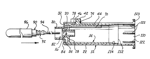
Referring jointly to Figures 1 and 2, a two
- part blood collection tube holder lO for detachably
supporting the hub of a double ended needle is
shown. The holder includes a cylinder 12 for
axially translatably supporting an insert 14. The
WO91/063322o 4~S 9fi PCT/US90/0630S
insert includes a hollow internally threaded boss 16
extending axially from closed end 18 of insert 14.
Threads 20 in the boss are engagable with the
conventional threaded hub of a double ended needle
and, through such threaded engagement, firmly
supports the needle. The insert includes a
posteriorly extending generally cylindrical skirt
22. The axial length of the skirt is configured
sufficient to house the posterior needle therein and
guard against inadvertent needle stick from the
posterior needle. A segment of an axially oriented
annular ridge 24 extends anteriorly from closed end
18.
Cylinder 12 is generally cylindrical in
configuration and includes a hollow collar 30
extending anteriorly from an annular flange 32
disposed at the anterior end of the cylinder. A
retaining finger flange 34 extends radially from the
posterior end of cylinder 12; this finger flange may
include a ridge 35 extending along the perimeter.
An axially aligned slot 36 extends between a
first circumferentially expanded slot segment 38 and
a second circumferentially expanded slot segment 40.
Insert 14 includes a tab 42 located generally at the
anterior end of a leaf spring 44 formed as part of
skirt 22. Upon mating of insert 14 with cylinder
12, tab 42 extends through slot 36 and expanded slot
segments 38,40 as a function of the translational
position of the insert with respect to the cylinder.
To facilitate thumb access to tab 42 during
exteriorization of the anterior needle in the
reusable configuration of holder 10, the upper edges
of wing 34 extending laterally in opposed directions
from expanded slot segment 40 may be cut down or
scalloped below the height of the tab.
Referring jointly to Figures 1-3, insert 14 is
illustrated in the needle retracted position with
W O 91/06332 PC~r/US90/0630~
g ;~
respect to cylinder 12. Tab 42 includes a base 46
having a lateral width approximately equivalent to
the circumferential spacing of expanded slot
segments 38,40. The height of the base is equal to
or greater than the thickness of cylinder 12
adjacent expanded slot segments 38,40. Accordingly,
the anterior edge of the base will bear against
anterior edges 48,50 of expanded slot segment 40 and
preclude anterior movement of the tab. Thereby,
insert 14 is positionally locked with respect to
cylinder 12 in the needle retracted position
illustrated. A pedestal 52 extends upwardly from
base 46 to support wing 54 of the ta~. The lateral
width of the pedestal is commensurate with the width
of slot 36 to accommodate translation of the
pedestal along the slot. Wing 54 extends in opposed
directions from pedestal 52 a sufficient distance to
prevent depression of tab 42 radially inwardly of
cylinder 12, whether the tab is within slot 36,
expanded slot segment 38 or expanded slot segment
40. Upon depressing tab 42 radially inwardly,
resulting in radial inward bending of leaf spring
44, pedestal 52 is brought into engagement with slot
36. Upon such engagement, the tab is translatable
axially along the slot resulting in commensurate
rectilinear motion of insert 14. To stabilize axial
translation of insert 14 within cylinder 12, a pair
of axially aligned ridges 56,58 extend posteriorly
from tab 42 along the leaf spring. A similar pair
of ridges 60,62 may extend anteriorly of tab 42.
The circumferential width defined by pair of ridges
56,58 and 60,62 is commensurate with the
circumferential width between edges 66,68 of slot
- 36. Accordingly, the two pairs of ridges, in
combination with the edges of the slot, minimize
rotation about the longitudinal axis of insert 14
with respect to cylinder 12. The degree of
W O 91/06332 PC~r/US90/0630~
1596
springiness provided by leaf spring 44 is a function
of, not only the material of skirt 22 of insert 14,
but of the length of slots 70,72 defining the
lateral edges of the leaf spring.
To translate insert 14 anteriorly with respect
to cylinder 12, tab 42 is depressed radially
inwardly to engage pedestal 52 with slot 36. Upon
anterior translation of the tab, base 46 will
ultimately become coincident with expanded slot
I0 segment 38. Upon such coincidence, the upward force
exerted by leaf spring 44 will cause the base to
penetrably engage anterior expanded slot segment 38.
In this position, posterior axial translation of
insert 14 is precluded by the rear edge of the base
engaging posterior edges 74,76 of expanded slot
segment 38, as illustrated in Figure 4.
To discourage inadvertent depression of tab 42
while it is in locked engagement with expanded slot
segment 38, a pair of walls 78,80 may be
incorporated on opposed sides of the expanded slot
segment. These walls are of a height and width
commensurate with the height and width of tab 42
when the latter is in locked engagement with
expanded slot 38. These walls will have the effect
of shielding the tab and guarding against
inadvertent depression of the taB with a resulting
release of the tab from the expanded slot segment,
yet access to the tab to deliberately depress it is
not impeded.
Collar 30 defines a passageway 82 of sufficient
diameter to accommodate partial penetration by boss
16, as shown in Figure 4. The positional rigidity
of boss 16 at the anterior end of cylinder 12 is
provided by a combination of factors. First, ridge
24 of skirt 22 bears against inner surface 84 of
annular flange 32 and is positionally maintained
thereagainst by base 46 of tab 42 bearing against
W O 91/06332 PC~r/US90/0630~
20~1~5~6
11
edges 74,76. Thereby, longitudinal stability of the
insert with respect to the cylinder is provided.
Second, the diameter of the anterior end of insert
14 proximate ridge 24 is in close tolerance with the
internal anterior diameter of cylinder 12 proximate
annular flange 32 to prevent lateral movement
therebetween.
Segmented annular ridge 24 serves three main
functions. First, it displaces the tab posteriorly
to accommodate a small angle of penetration during
venipuncture. Second, it displaces the contact
point between the posterior needle and the blood
collection tube posteriorly to provide greater
gripping surface upon the blood collection tube.
Third it enhances the longitudinal surface area
between the insert and the cylinder.
A conventional commercially available double
ended needle 90 having a threaded hub 92 is used
with holder 10. To secure double ended needle 90 to
holder 10, the conventional shield protecting
posterior needle 94 and its associated valve is
removed. Such removal will expose threaded hub 92.
The posterior needle is inserted through collar 30
and boss 16 to threadedly engage the needle hub with
threads 20 within the boss. The hub of the double
ended needle includes an anterior needle shield
support structure 100 terminated by a radially
extending flange 102 for supporting a conventional
shield 96. Just prior to venipuncture, shield 96 is
disengaged from support structure 100 and removed to
expose anterior needle 98 (see Figure 5).
As part of the blood collection procedure, a
blood collection tube having a needle penetrable
stopper is inserted through the open posterior end
110 of cylinder 12, through open posterior end 112
of insert 14 and into penetrable engagement with
posterior needle 94. To assist and ease insertion
WO91/06332 PCT/US90/06305
2044596
12
of the blood collection tube within insert 14, the
inside surface of posterior end 112 may be formed as
an annular ramp 114.
On completion of the blood collection procedure
and withdrawal of the last blood collection tube, a
phlebotomist or other medical personnel can hold
cylinder 14 in the palm of the hand and lightly
grasp the cylinder with the fingers. The thumb can
be used to depress tab 42 and thereafter crook the
thumb to draw the tab posteriorly, as illustrated by
arrow 120 in Figure 6. The posterior movement of
tab 42 will result in commensurate movement of
insert 14 with respect to cylinder 12. When base
46 of tab 42 comes into correspondence with expanded
slot segment 40, leaf spring 44 will urge upward
movement of the tab to bring base 46 into engagement
with the expanded slot segment. In the resulting
position of insert 14, anterior needle 98 will have
been drawn completely into the interior of cylinder
12. In this position of the anterior needle,
inadvertent needle stick by the anterior needle will
be impossible. The axial length of insert 14 is
greater than the length of posterior needle 94 and
the posterior needle will be contained completely
therewithin. Thereby, inadvertent needle stick from
posterior needle 94 will also be precluded by the
shielding effect of skirt 22, as depicted in Figure
6.
For manufacturing reasons, the interior surface
of cylinder 12 tapers radially outwardly
posteriorly. SUch tapering will permit some radial
movement of the anterior end of insert 14 when the
insert is in the needle retracted position shown in
Figure 6. To maintain anterior needle 98 generally
coincident with the longitudinal axis of cylinder
12, a plurality of tapered longitudinally extending
ridges 122 are disposed internal to the posterior
WO91/06332 PCT/US90/0630~
_ 13 Z044596
end of cylinder 12, as depicted in Figure 4. A
plurality of these ridges, such as 6, equiangularly
spaced about cylinder 12, reduce the effective
diameter of the cylinder at its posterior end into
general conformance with the exterior diameter of
the anterior end of insert 14. Thereby, the
anterior end of insert 14 is positionally stabilized
by the ridges to prevent wobble and misalignment of
anterior needle 98 with the longitudinal axis of
cylinder 12. Necessarily, the dimensional intrusion
of tapered ridges 122 must be commensurate with the
difference in diametric dimension between the
posterior internal end of cylinder 12 and the
external diameter of the anterior end of insert 14.
Alternatively or in conjunction with ridges 122, the
radial exterior of ridges 56,58 can be increased
proximate tab 42 to bring about contact with arch
123 in finger flange 34 upon posterior displacement
of insert 14. The resulting physical contact will
reduce the likelihood of wobble and maintain the
anterior needle axially aligned with the cylinder.
Accordingly, in the needle retracted position
shown in Figure 6, the axial position of insert 14
with respect to cylinder 12 is stabilized by
engagement of tab 42 with expanded slot segment 40.
Radial stability, to prevent wobble, between the
insert and the cylinder is provided by the plurality
of tapered ridges engaging the circumferential
surface of the anterior end of insert 14. This
stability is important for two primary reasons.
First, it permits aligned reextension of anterior
needle 98 through passageway 82 of collar 30.
Second, as will be described below, it permits
capping of anterior needle 98 by sliding a needle
shield through passageway 82 to cover the anterior
needle.
WO9l/06332 PCT/US90/0630~
Z044S~6
14
Referring jointly to Figures 7 and 8, there is
shown a top view of holder 10 and an end view
thereof. These views clearly illustrate leaf spring
44 extending anteriorly as part of insert 14 and
defined by slits 70,72. Tab 42 has been brought
posteriorly adjacent finger flange 34 to position
anterior needle 98 in the retracted position.
Ridges 56,58 extending radially outwardly from leaf
spring 44 slidably engage slot 36, as depicted by
anterior extensions 60,62 of these ridges. In the
retracted position, base 46 of tab 42 is lockingly
engaged within expanded slot segment 40 to preclude
anterior translation of insert 14 without an
accompanying depression of tab 42 to disengage the
base from the expanded slot segment. As
particularly noted in Figure 8, needle 98 is
essentially axially centered with passageway 82 of
collar 30.
After completion of a blood collection
procedure, holder 10 may be discarded or the holder
may be reused with a replacement needle. To replace
the double ended needle, a standard conventional
anterior needle shield used as part of the packaging
for the double ended needle is used. The open end
of shield 96 is inserted through passageway 82 into
cylinder 12 while tab 42 is locked in expanded slot
segment 40. Continued downward movement of the
shield, as depicted by arrow 132 shown in Figure 9,
will ultimately enclose the needle and the shield
will come into engagement with support structure 100
of the hub of the double ended needle. For most
commercially available double ended needles, the
engagement of the shield with the hub is a simple
press fit. At this point, a user has two options
for removing the double ended needle. First, shield
96, after engaging the hub of the double ended
needle, can be rotated to bring about threaded
WO91/06332 PCT/US90/06305
Z044596
disengagement between the hub and boss 16 of insert
14. Upon such disengagement, shield 96 is withdrawn
and the anterior needle will be lodged therein.
Secondly, as depicted in Figure 10, tab 42 may be
translated anteriorly to extend shield 96 and the
enclosed needle. With such extension, a greater
gripping area of the shield will be available for a
user. Accordingly, extension of the shield prior to
threaded disengagement of the double ended needle
from boss 16 may be more facile. After removal of
the double ended needle, the posterior needle may be
capped with the shield initially supplied with the
double ended needle. Such capping is performed by
holding shield 96 to stabilize and positionally
maintain the posterior needle during capping.
Holder 10 is now ready to receive a replacement
needle. Collar 30 may be adapted diametrically to
receive and seat the proximal end of the shield in
preparation for penetration and lodgment of the
anterior needle within the shield.
Under certain circumstances, it may be
preferable to preclude reuse of holder 10. Such
reuse can be precluded by rendering tab 42
inaccessible upon placement of the tab within
expanded slot segment 40. Referring to Figures 11
and 12, there is illustrated a guard 140 usable for
this purpose. Side walls 142,144 extend outwardly
from cylinder 12 at opposed sides of expanded slot
segment 40. A cover 146 interconnects the upper
edges of the side walls at a location just above
wing 54 of tab 42. The side walls and cover extend
anteriorly from wing 34 a sufficient distance to
totally enclose the tab.
When tab 42 is drawn posteriorly during
retraction of the double ended needle, it will slide
into guard 140. Upon entering within the guard,
base 46 of the tab will become coincident with
W O 91/06332 PC~r/US90/0630~
2044~S96
16
expanded slot segment 40 and due to spring action of
leaf spring 44, the tab will pop up into close
proximity with cover 146. In this position, the tab
will be difficult to access and without
extraordinary measures, the retracted double ended
needle cannot be extended. Accordingly, the
configuration of holder 10 illustrated in Figures 11
and 12 provides a non reusable blood collection tube
holder. To augment difficulty in withdrawing tab 42
from within guard 140, a pair of ramps 130,132 can
be formed on cylinder 12. These ramps are disposed
on opposed sides of slot 36 and extend toward and
terminate at anterior edges 48,50 of expanded slot
segment 40. The height of these ramps permits
travel thereover of wing 54 during posterior travel
of tab 42. Under certain circumstances, a single
ramp on one side of slot 36 may be adequate. The
locking feature of the ramps operates as follows.
To reposition tab 42 anteriorly, the tab must be
depressed to disengage, radially inwardly, base 46
from expanded slot segment 40. Such depression of
the tab will lower wing 54 to a location against the
butt end of the ramps. The butt end of the ramps
will interfere with anterior relocation of tab 42
and the tab becomes mechanically locked within guard
140.
Cylinder 12 and insert 14 of holder 10 are
manufacturable relatively inexpensively through use
of molds. After manufacturing, the holder must be
assembled. Such assembly is relatively easily
performed in the following manner. The anterior end
of leaf spring 44 of insert 14 is depressed
sufficiently to permit insertion of the insert and
tab within the open posterior end of cylinder 12.
By axially rotating the insert when tab 42 is either
proximate expanded slot segment 38 or 40, the insert
is rotated about its longitudinal axis to position
W O 91/06332 PC~r/US90/06305
17 20~S~
one end of wing 54 within the expanded slot segment.
By slightly twisting the tab, the end of the wing
can be made to protrude the respective expanded slot
segment. Further axial rotation of the insert and
commensurate depression of the cylinder along one
side of the slot will permit one half of the wing to
extend over the lateral edge of the expanded slot.
Thereafter, the opposite wing can be popped radially
outwardly and over the opposed cylindrical surface
adjacent the expanded slot. By rotating insert 14
in the opposite direction, ridges 56,58 and 60,62
can be brought into alignment with slot 36 and upon
such alignment, leaf spring 44 will spring radially
outwardly to its quiescent position. Rectilinear
translation of the insert with respect to the
cylinder can now readily be effected. While
disengagement of the insert from the cylinder can be
accomplished by essentially reversing the above
discussed procedure, such disengagement must be a
very deliberate and affirmative act and is likely to
result in breakage. Accordingly, during normal use
of holder 10, disengagement cannot and will not come
about. Test results indicate that a pulling force
in the range of 25 to 40 pounds is required to
disengage shield 14 from cylinder 12 due to the
interference between tab 42 and finger flange 34.
State of the art related blood collection tube
holders come apart and expose the double ended
needle upon application of a two-thirds or less
pulling force. One may therefore conclude that
inadvertent detachment of the insert from the
cylinder will not occur during any expected use of
holder 10. Holder 10 is intended to be used with
commercially available sterilized double ended
needles of standard configuration. The procedure
attendant venipuncture does not require
sterilization of holder 10. Accordingly,
W O 91/06332 PC~r/US90/0630~
20~6
18
sterilization of a holder being manufactured may be
avoided. Furthermore, since the holder does not
have to be sterilized nor maintained sterile, the
handling of the holder in a physician's office,
clinic or hospital will require no new or different
procedures. The use of holder 10 permits employment
of stAn~Ard venipuncture procedures except for one
small modification. At the venipuncture site or
shortly thereafter and before the medical personnel
releases the holder, tab 42 is translated by a very
simple convenient thumb motion to retract the
anterior needle. Thereafter, the holder may be
immediately disposed of or placed on a tray for
later disposal or reuse, all without creating a
danger of inadvertent needle stick. The very
compact size of being essentially not much longer
than a standard double ended needle substantially
reduces storage space requirements both prior to and
during a venipuncture procedure. Furthermore, the
minimal size lessens the space required of
containers for disposables. The dimensions of the
holder permit use of short blood collection tubes
and all size commercially available double ended
needles. Aside from the above discussed methods for
capping or disposing the double ended needle, other
methods may be exercised. While the anterior needle
is exposed after use, the anterior needle may be
inserted into its original cap or shield lying on a
support surface. An upward hooking motion of the
holder will cause the cap to slide onto the needle.
Thereafter, the cap may be frictionally engaged with
the needle hub to maintain the cap in place. To
separate the double ended needle from the holder,
the cap is turned to unthread the needle engagement
between the hub and the boss of the insert and the
double ended needle is withdrawn. Secondly, certain
bio hazard containers include a clamp like device
W O 91/06332 PC~r/US90/0630~
19 ~ 6
for gripping objects. The exposed anterior needle
may be clamped in the bio hazard container and
thereafter disengaged from the holder by turning the
holder to unthread the needle hub from the insert.
Alternatively, if the configuration of cylinder 12
permits exteriorization of the needle hub from
collar 30, the needle hub may be gripped by the bio
hazard device and twisted to disengage the double
ended needle from the holder.