Note: Descriptions are shown in the official language in which they were submitted.
~o~~~r9~
2
INJECTION PiOLDING I~NIFOLD 6aITH TNTEGRAL
HEATED INLET PORTION
BACKGROUND OF THE INVENTION
This invention relates generally to injection
molding and more particularly to an injection molding melt
distribution manifold having an integral heated inlet
portion.
Steel manifolds are mounted in an injection
molding system and have a melt passage with a common inlet
and a number of spaced outlets to distribute pressurized
melt received from a molding machine to a number o~
different gates. Each system can have one or more
manifolds with a variety of different configurations
depending upon a number of factors, such as the number of
gates, size and shape of the cavities, and type of material
being molded. These manifolds are often heated to
compensate i:or heat loss to the surrounding cooled cavity
wv
3
and bank plates and maintain a more uniform temperature of
the melt flowing through them. Gellert Canadian patent
application serial number 2,017,055 filed May 17, 1990
entitled "Injection Molding Cast Manifold" shows an example
of a manifold having an integral electrical heating element
extending around a tortuous path.
Canadian application serial no. 2,017,055 also
shows the manifold having an extension which extends
rearwardly to receive melt from the molding machine. The
manifold extension does not have a heating element and is
fastened to the manifold by bolts. U.S. patent nos.
4,669,971 to Gellert which issued June 2, 1987 and
4,777,348 to Gellert which issued October 11, 1988 disclose
earlier examples of manifold extensions which are fastened
to the manifold by screws. U.S. patent no. 4,438,325 to
Gellert shows a heater cast which acts as a manifold
extension and has a heating element separate from the
heating element in the manifold. While this configuration
is satisfactory for many applications, problems can arise
in controlling the temperature of two different heating
elements and in fastening the manifold extension to the
manifold. lFurthermore, the increasing demand for systems
having greater numbers of gates has made compact component
size even mare critical.
\.
4
SiJMMARY OF TH:E INVENTION
Accordingly, it is an object of the present
invention to at least partially overcome the problems of
the prior art by providing a melt distribution manifold
having a common electrical heating element extending
through integral main and inlet portions.
To this end, in one of its aspects, the invention
provides an injection molding melt distribution manifold
having a main portion with a forward face and a rear face,
a melt passage extending therethrough and branching therein
to a plurality of spaced outlets on the forward face, an
integral electrical heating element extending from an
external terminal in a predetermined tortuous path in the
main portion, having the improvement wherein the manifold
has an integral inlet portion extending rearwardly from the
rear face of the main portion, the inlet portion having a
cylindrical outer surface and a rear end, the melt passage
extending centrally through the inlet portion from an inlet
at the rear end, and the electrical heating element having
a rear helical portion extending around the inlet portion.
Further objects and advantages of the invention
will appear from the following description, taken together
with the accompanying drawings.
~0~~'~9~
BRTEF DESCRIPTION OF THE DRAWINGS
F figure 1 is a plan view of four heated probes
mounted in a heated manifold according to a preferred
embodiment of the invention,
5 Figure 2 is a partial sectional view showing the
probes and manifold along line 2 - 2 in Figure 1 and a
portion of the surrounding mold, and
Figure 3 is a sectional view of the manifold
itself along line 3 - 3 in Figure 1.
DETAILED DESCRIPTION OF THE DRAWINGS
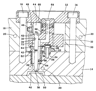
Reference is first made to Figure 2 which shows
a melt distribution manifold 10 according to a first
embodiment of the invention mounted in a mold between a
locating ring 12 and a cavity plate 14. The locating ring
12 is secured in position by bolts 16 which extend through
a support plate 18 into the cavity plate 14. The cavity
plate 14 and the support plate 18 are cooled by pumping
cooling water through cooling conduits 20. In addition to
the locating ring 12, the manifold 10 is located centrally
by a locating member 22 which is secured in a seat 24 in
the cavity plate 14 by a bolt 26 and which extends into a
matching seat 28 in the manifold 10. As is well known, the
heated manifold 10 is thermally separated to a considerable
extent from the surrounding cooled components of the mold
6
by an insulative air space 30,. Thus, in order to reduce
heat loss, steel to steel contact is minimized between the
inner heated components and the surrounding outer cooled
components.
As also seen in Figure 1, in this embodiment of
the invention each manifold 10 has four heated probes 32
extending therethrough. As described in Gellert Canadian
patent application serial no. 2,032,728 filed December 19,
1990 entitled "Injection Molding Probe with Varying Heat
Profile", each probe 32 extends through a bore 34 through
the manifold 10 into a well 36 in the cavity plate 14. As
seen in Figure 2, each well 36 leads to a gate 38 which
extends through the cavity plate 14 to a cavity 40. While
the system shown has four probes 32 aligned with four gates
38-leading to four different cavities 40, other systems can
have a different number of gates 38, and the gates can all
lead to a common larger cavity. Each probe 32 has an
elongated cylindrical forward portion 42 and a larger
diameter rear head portion 44. The rear head portion 44
has an outwardly extending electrical terminal 46 to
receive a lead 48 from an external power source (not
shown). The forward portion 42 has a pointed forward end
50 which is aligned with the gate 38. The forward portion
42 of the probe 32 is accurately located in this position
by a locating and insulating sleeve 52 which is seated in
7
the well 36 around it. As shown in Canadian patent
application serial no. 2,032:,728 mentioned abovey the
locating and insulating sleeve 52 has three radial locating:
fins 54 which extend inwardly to contact the forward
portion 42 of the probe 32, but allow the melt to flow
between them. A thermocouple 56 extends into a bore 58 in
one of the fins 54 to monitor the temperature of the melt
flowing past it.
Bolting the locating ring 12 against the rear
ends 60 of the probes 32 also :accurately locates the
manifold 10 and the probes 32 longitudinally. The head
portion 44 of each probe 32 has a shoulder 62 which abuts
against the manifold 10. Each locating sleeve 52 has a
rear collar portion 64 which extends outwardly between the
manifold 10 and the cavity plate 14. Thus, the manifold 10
can receive the repeated injection forces from the molding
machine (not shown) without disturbing the accurate
location of the pointed forward ends 50 of the probes 32
relative to their respective gates 38. The pressure
applied to; the rear collar portions 64 of the locating
sleeves 52.by the bolts 26 also seals against leakage of
pressurized melt flowing through the melt passage 66. The
melt passage 66 branches in the manifold 10 from a common
inlet 68 and extends through each locating sleeve 52 into
the well 36 to the respective gate 38. Each bore 34
8
through the manifold 10 has a rear portion 70 and a larger
diameter forward portion 72. The diameter of the rear
portion 70 is just large enough to snugly receive the
forward portion 42 of the probe 32 to prevent leakage of
the pressurized melt between them. The diameter of the
forward portion 72 matches the inner diameter of the
locating sleeve 52 and is large enough to allow the melt to
flow through the melt passage 66 around the forward portion
42 of the probe 32.
Reference is now made to Figure 3 which shows a
manifold 10 according to a preferred embodiment of the
invention. The manifold 10 has a main portion 74 and an
integral inlet portion 76. The main portion 74 has a
forward face 78 and a rear face 80. The inlet portion 76
has a cylindrical outer surface 82 and extends rearwardly
from the rear face 80 of the main portion 74 to a rear end
84. The melt passage 66 extends centrally through the
cylindrical inlet portion 76 from the inlet 68 at the rear
end 84 and branches in the main portion 74 to four spaced
outlets 86 (Figure 2) on the forward face 78.
The manifold 10 also has an integral electrical
heating element 88 which extends from an external terminal
90 through both the main portion 74 and the integral inlet
portion 76. In this embodiment of the invention, the
heating element 88 has a forward portion 92, a central
9
portion 94, and a rear helical portion 96. The forward
portion 92 extends from the external terminal 90 along a
tortuous path 98 (Figure 1) adjacent the forward face 78 of
the main portion 74 of the manifold 10. The central
portion 94 of the heating element 88 then extends
rearwardly through the main portion 74 of the manifold 10
to the rear helical portion 96 which extends around 'the
cylindrical inlet portion 76 of the manifold 10. In this
embodiment, the heating element 88 has a nickel-chrome
resistance wire 100 which is grounded at the rear end of
the heating element. The resistance wire 100 extends
through a refractory powder such as magnesium oxide in a
steel casing 102. In another embodiment, the forward
portion of the heating element can extend along a tortuous
path adjacent the rear face 80 of the main portion 74 of
the manifold and then connect directly to the rear helical
portion of the heating element extending around the
cylindrical inlet portion of the manifold.
A manifold 10 according to the preferred
embodiment of the invention is manufactured as follows.
The main portion 74 and cylindrical inlet portion 76 are
machined out of steel. The main portion is gun drilled and
plugged to form the melt passage 66 similar to the method
described in U.S. patent no. 4,609,138 to Harrison which
issued September 2, 1986. A channel 104 is cut along a
2fl44~9~
predetermined tortuous path 98 in the forward face 78 of
the main portion 74. Installation of an electrical heating
element in a channel cut in a manifold is described in U.S.
patent no. 4,688,622 to Gelle:rt which issued August 25,
5 1987. A hole 106 is drilled from this channel 104 through
the main portion 74 of the manifold 10 to connect to a
spiral channel 108 which is cut around the cylindrical
outer surface 82 of the inlet portion 76 of the manifold.
Installation of an electrical heating element in a spiral
10 channel cut in the surface of a cylindrical nozzle is
disclosed in U.S. patent no. 4,768,283 to Gellert which
issued September 6, 1988. After the heating element is
wound in place in the spiral channel 108 around the inlet
portion 76, it is pulled through the bore 106 through the
main portion 74 and the inlet portion 76 is mounted in
place on the main portion 74. The heating element is then
wound in place in the channel 104 in the main portion 74
and the external terminal 90 is installed as described in
U.S. patent no. 4,837,925 to Gellert which issued June 13,
1989. As can be seen in Figure 3, in this embodiment, the
spiral channel 108 has a wide portion 110 closest to the
rear end 84 of the inlet portion 76 wherein several coils
112 of the rear helical portion 96 of the heating element
88 are wound side by side. This provides additional heat
to compensate for heat lost through contact with the
11
locating ring 12. Different amount's of heat can also be
provided to different locations by cutting the spiral
channel 108 with a predetermined varying pitch.
A nickel alloy brazing material is then applied
to the outer surfaces of the assembled main and inlet
portions 74, 76 before they are heated in batches in a
vacuum furnace. In this embodiment, as the furnace is
gradually heated to a temperature of approximately 2000°
F., the furnace is evacuated to a relatively high vacuum to
remove nearly all the oxygen. Before the melting point of
the nickel alloy is reached, the vacuum is reduced by
partially backfilling the furnace with an inert gas such as
nitrogen. When the nickel alloy melts, it flows by
capillary action around the heating element 88 to fill the '
hole 106 and channels 104, 106 and integrally embed the
heating element 88. The molten nickel alloy also flows
between the main partion 74 and the inlet portion 76 to
integrally bond them together. Brazing in a vacuum furnace
provides a metallurgical bonding of the components which
improves the efficiency of heat transfer from the heating
element 88. After the manifolds 10 are cooled and removed
from the vacuum furnace they are machined to remove any
excess material.
In use, the injection molding system is assembled
as shown in figure 2. Electrical power is applied to the
12
heating element 88 in the manifold 10 and to the heating
element in each probe 32 to heat them to a predetermined
operating temperature. Pressurized melt from a molding
machine (not shown) is then injected into the melt passage
66 through the common inlet 68 according to a predetermined
cycle in a conventional manner. The pressurized melt flows
through the heated manifold 10 where it branches to flow
along around each heated probe 32 and through the gates 38
to fill the cavities 40. After the cavities are filled,
injection pressure is held momentarily to pack and then
released. After a short cooling period, the mold is opened
to eject the molded products. After ejection, the mold is
closed and injection pressure is reapplied to refill the
cavities 40. This cycle is continuously repeated with a
frequency dependent on the size and shape of the cavities
and the type of material being molded.
While the description of the heated manifold has
been given with respect to a preferred embodiment, it will
be evident that various modifications are possible without
departing from the scope of the invention as understood by
those skilled in the art and as defined in the following
claims. For instance, it is apparent that a number of
manifolds according to the invention can be used in an
injection molding system to receive melt from a common
bridging manifold which, in turn, receives melt from the
--
13
molding machine. This multiplies the number of cavities
which can be filled at the same time, but retains the
advantages of the present invention that each manifold is
very compact and the main and inlet portions 74, 76 are
integral or monolithic and hays: a common heating element.