Note: Descriptions are shown in the official language in which they were submitted.
CA 02044960 2000-04-OS
1
ZEOLITES NU-85
The present. invention relates to a novel
crystalline aluminosi:Licate zeolite designated NU-85, a
method of making it and to processes using it as a
catalyst.
As the actual structure of crystalline zeolites
is often unknown; these materials are usually characterised
by their X-ra.y powder diffraction pattern, molar
composition and soz-ptive and catalytic properties.
Techniques such as electron diffraction, transmission
electron microscopy and magic-angle spinning nuclear
magnetic resonance spectroscopy can, however, be used to
give additional information on certain structural features
which would not, otherwise, be observed.
Even wren the basic framework structure is known,
additional information may be required to distinguish
between two materials. For example, zeolite X and Y have
the same basic topology but differ in the ratio of silica
to aluminia in the structural framework. Another example is
large- and small-port mordenite. These materials have the
same X-ray powder diffraction pattern yet have different
molecular sieve properties with the large port material's
sorption being consistent with the known framework
topology. The reason for these differences has been
attributed to the f<~ct than the small port material
contains structural blockages within its channels, which,
it has been reported, can be observed by electron
diffraction.
Materials which are intergrowths of two zeolites
having different topologies also exist. Such materials are
CA 02044960 2000-04-OS
la
not simple mixtures. 'they are materials in which bands of
both zeolites exist within individual crystals. Such
intergrowths are new materials since they have properties
which can distinguish them from the individual "parent"
zeolites. Inter<~rowths based on erionite/offretite and
ZSM-5/ZSM-11 have been described in US Patents 4 086 186
and 4 229 424 re;~pectiwely.
Intergrowths may be characterised by electron
diffraction and/or transmission electron microscopy.
However, it is possible that the intergrowths may have
distinct X-rav powder
2 H35799
diffraction patterns which differ from the parent zeolites. For
example, US Patent 4 086 186 describes a novel aluminosilicate
material, designated ZSM-34, which is an intergrowth of
erionite-offretite and which has an X-ray powder diffraction
pattern which is different from that of either erionite or
offretite. Another example is zeolite T which is the subject of
US 2950952. This is described in "Zeolite Molecular Sieves", D W
Breck, published by J Wiley & Sons, 1974, p81 as a "disordered
intergrowth" of offretite and erionite". Like zeolite ZSM-34,
the X-ray powder diffraction of this material is different from
that of the parent zeolites.
It has now been found that an intergrowth of zeolite
EU.-l, described in European Patent No 42 226, and zeolite NU-87,
described in European Patent Specification No 377 291 can be
produced.
The contents of EP-B-42 226 and EP-A-377 291 are
incorporated herein by reference. However, for convenience,
brief definitions of the zeolites EU-1 and NU-87 are given below.
Zeolite EU-1 has a molar composition expressed by the
formula:
0.5 to 1.5 R20:Y203: at least 10 X02:0 to 100 H20
wherein R is a monovalent cation or 1/n of a cation of valency n,
X is silicon and/or germanium, Y is one or more of aluminium,
iron, gallium or boron, and H20 is water of hydration additional
to water notionally present when R is H and, in its "as-prepared"
form, an X-ray diffraction pattern including the lines given in
Table A.
3 H35799
TABLE A
2eolite EU-1 "as prepared"
d(Angstrom) Relative Intensity
11.03 Very Strong
10.10 Strong
9.72 Weak
6.84 Weak
5.86 Very Weak
4.66 Very Strong
4.31 Very Strong
4.00 Very Strong
3.82 Strong
3.71 Strong
3.44 Medium
3.38 Medium
3.26 Strong
3.16 Very Weak
3.11 Very Weak
2.96 Very Weak
2.71 Very Weak
2.55 Weak
2.48 Very Weak
2.42 Very Weak
2.33 Very Weak
2.30 Very Weak
2.13 Very Weak
H35799
Zeolite NU-87, has a molar composition expressed by the
formula: 100 X02: equal to or less than 10 Y20g: equal to or less
than 20 R2/n0 where R is one or more cations of valency n, X is
silicon and/or germanitun, Y is one or more of aluminium, iron,
gallitun, boron, titanium, vanadium, zirconium, molybdenum,
arsenic, antimony, chromium and manganese and, in its
"as-prepared" form, an X-ray diffraction pattern including the
lines given in Table B.
Ii35799
Table B - Zeolite NtJ-87 "as-prepared"
d(Angstroms) Relative Intensity (d)
5 12.52 +/- 0.15 w
11.06 +/- 0.15 s
10.50 +/- 0.15 m
8.31 +/- 0.15 w
6.81 +J- 0.12 w
4.62 +/- 0.10 m-s
(a) 4.39 (Sh)+/- 0.10 m-s
4.31 +/- 0.10 vs
4.16 +J- 0.10 m
3.98 +/- 0.08 s-vs
(b) 3.92 (Sh)+/- 0.08 s
3.83 +/- 0.08 w-m
3.70 +/- 0.07 m-s
3.61 +/- 0.07 w
3.41 +/- 0.07 m-s
(c) 3.37 (Sh)+/- 0.07 m
3.26 +/.- 0.06 s-vs
3.15 +/- 0.06 w
3.08 +/- 0.06 w
2.89 +/- 0.05 w-m
2.52 +/- 0.04 w-m
(Sh) denotes that the
peak occurs
as a shoulder
on a
more intense peak
(a) occurs on the low side of the peak
angle at about
4 . 31~.
(b) occurs on the high side of the peak
angle at about
3.98t~.
(c) occurs on the high side of the peak
angle at about
3.41t'~.
6 H35799
(d) Based on a relative intensity scale in ~ahich the
strongest line in the X-ray pattern is assigned a value
of 100:
weak (w) is less than 20
medium (m) is between 20 and 40
strong (s) is greater than 40 but less than 60
very strong (vs) is greater than 60.
As described in EP-B-42 226, zeolite EU-1 is preferably
prepared from a reaction mixture containing
Si02 - A120g - Na20 - Q - H20
where Q is a polymethylene alpha omega-diammonium cation, and is
preferably hexamethonium - hexane - 1,6 - bis (trimethylammonium)
ie
C(CH3)3N(CH2)6N(CH3)3~2+
The mixture is usually reacted a temperature between 85 and
250°C.
As described in EP-A-377 291, zeolite NU-87 is
preferably prepared ~rom a reaction mixture containing:
Si02 - A120g - Na20 - Q - H20
where Q is most preferably
~(CH3)3N(CH2)10N(CH3)3l2+
The mixture is usually reacted a temperature between 85 and
250°C.
Surprisingly, we have now found that certain
combinations of reaction mixture composition and temperature
produce a novel and useful material, designated zeolite NU-85,
which we have identified as an intergrowth of zeolites EU-1 and
NU-87.
According to the present invention, zeolite NU-85
comprises crystals containing discreet bands the structures of
which are individually characteristic of the structures of
zeolite EU-1 and zeolite NU-87, said bands exhibiting substantial
crystal lattice continuity therebetween.
According to a further aspect the invention provides a
zeolite, designated zeolite NU-85, having a composition expressed
7 H35799
on an anhydrous basis, in terms of mole ratios of oxides, by the
formula:
100X02 : less than or equal to 10Y203: less than or equal to
20R2/n0
where R is one or more cations of valency n, X is silicon and/or
germanium, Y is one or more of aluminium, iron, gallium, boron,
titanium, vanadium, zirconium, molybdenum, arsenic, antimony,
chromium and manganese and having, in its as prepared form
lattice images which, when orientated to show the 20.2 +/- 0.2
.Angstrom fringes of zeolite EU-1 exhibit intergrown 12.5 +/- 0.2
Angstrom fringes together with said 20.2 +J- 0.2 Angstrom fringes
and/or an X-ray diffraction pattern including the lines shown in
Table 1.
The invention also provides zeolite NU-85 in its
hydrogen form, produced by calcination and/or ion exchange as
described herein.
By "zeolite NiT-85" we mean s family of materials the
compositions of which can be equated to varying proportions of
the two parent zeolites, EU-1 and NU-87. The result of this is
that the lines in the X-ray powder diffraction patterns of
different samples of zeolite NU-85 may have different
intensities. Without being bound by theory, it is believed that
the lower the intensity of the XRD (X-ray diffraction) line at
3.8 ~. (23.5 degrees two-theta) compared to the line at 3.7 ~ (24
degrees two-theta) the greater the proportion of zeolite NU-87 in
the intergrowth crystal. It is believed that this relationship
will apply to zeolite NU-85 containing up to at least 50Z zeolite
NU-87 in the intergrowth crystal.
g H35799
Table 1 - Zeolite NU-85 as-prepared
d(Angstroms) Relative Intensity*
11.15 +/- 0.20 m
10.30 +/- 0.20 w (a)
6.89 +/- 0.12 w
4.66 +/- 0.10 m
4.31 +/- 0.10 vs
4.00 +/- 0.08 s - vs
3.86 +/- 0.08 w - m
3.71 +/- 0.07 m (b)
3.42 +/- 0.06 w - m
3.37 +/- 0.06 w - m (c)
3.26 +/- 0.06 s - vs
3.16 +/- 0.06 w
3.10 +/- 0.06 w
2.96 +/- 0.05 w
2.71 +/- 0.05 w
* Based on a relative intensity scale in which the strongest line
in the ~-ray pattern is assigned a value of 100:
w (weak) is less than 20
m (medium) is between 20 and 40
s (strong) is greater than 40 and less than 60
vs (very strong) is greater than 60
It has to be noted, and as will be appreciated by those skilled
in the art, the data given in Table 1 is data obtained from a
relatively pure sample of material. When the zeolite 13U-85 is
relatively pure, the following relationships (a), (b) and (c) as
identified in Table 1 apply:-
a) - The ratio of the intensities (rounded to one decimal place)
of the line at 10.30X to the line at 11.15 is not more than 0.5.
g H35799
b) - The ratio of the intensities (rounded to one decimal place)
of the line at 3.86 to the line at 3.71. is not more than 1Ø
c) - The ratio of the intensities (rounded to one decimal place)
of the line at 3.37 to the line at 3.42 is not more than 1Ø
In less pure samples, the relationships (a) and (c) may
not always be present. However, the X-ray diffraction pattern of
zeolite NU-85 will show relationship (b) above, that is the ratio
of the intensities of the line at 3.86 to the line at 3.71. is
not more than 1Ø A sample of zeolite NU-85 will preferably
also show relationship (a) above in its XRD, that is the ratio of
the intensities of the line at 10.30 to the Line at 11.15 is
not more than O.S; and, in particular, will most preferably also
show relationship (c) above, that is the ratio of the intensities
of the line at 3.37 to the line at 3.42 is not more than 1Ø
In some cases broadening of lines at d-spacings of 10.3
+/-0.20, 3.86 +/-0.08 ~ and 3.37 +/- 0.06 may mean that a peak
picking computer program may produce more than one line in these
regions. In such instances, the strongest line in the 10.3, 3.86
and 3.37 Angstrom regions should be compared with the strongest
line in the 11.15, 3.71 and 3.42 Angstrom regions respectively.
Impurities found in samples of zeolite NU-85 include
alpha-quartz and analcime which have XRD lines which coincide
with the lines given in Table 1 above. For example, alpha-quartz
has its strongest XRD line at 3.34 ~. If present as an impurity
in a sample of zeolite NU-85, it will enhance the XRD line at
3.37 ~ and therefore, the XRD pattern of the sample will be more
akin to that expected for zeolite EU-1. By contrast analcime,
found as an impurity in many samples of zeolite NU-85, has a
strong line at 3.43 ~ in its XRD pattern. If present in a sample
of zeolite EU-1, analcime will enhance the XRD line at 3.42 ~
with the result that its XRD pattern will resemble the XRD
pattern for zeolite NLJ-85. In view o~ this it will be readily
appreciated by those skilled in the art that care must be
H35799
exercised in deciding whether a particular sample is zeolite
NU-85 based on XRD data alone.
The X-ray powder diffraction data provided herein were
obtained with a Philips APD 1700 automated X-ray diffraction
5 system using Cu K-alpha radiation from a long fine focus X-ray
tube operating at 40 KV and 50 mA. The radiation was
monochromatised by a curved graphite crystal adjacent to the
detector. An automatic theta-compensating divergence slit was
used with a 0.1 mm receiving slit. Step scanned data were
10 collected between 1 and 60 degrees two-theta. The collected data
was analysed in a DEC (Digital Equipment Corporation) Micro PDP
-11/73 computer with Philips PST 1867/87 version 3.0 software.
The X-ray computer intensities given herein are based on peak
height.
The XRD pattern for zeolite Nt?-85 is similar to that
found for zeolite EU-1, except that the former contains certain
characteristic lines which have a lower intensity compared to
those found for samples of EU-1 prepared according to
EP-B-42 226. The three principal lines which fall into this
category are those at d-spacings of 10.3 +/- 0.20; 3.86 +/- 0.08
and 3.37 +/- 0.06 Angstroms. Furthermore, the lines at about
10.3 and 3.86 Angstroms are selectively broadened and are shifted
to higher d-spacings compared to the corresponding lines in the
XRD for EU-1.
The XRD pattern for zeolite NU-85 differs from that found
for samples of zeolite NU-87, prEpared according to EP-A-377291
in that it does not contain, amongst others, lines at d-spacings
of 12.52 +/-0.15 and 8.31 +/-0.15 Angstroms, which lines are
characteristic of zeolite NU-87.
The lattice image data (and electron diffraction data)
provided herein were obtained using either a Philips EM400T
Transmission Electron Microscope (TEM) operating at 120 KeV or a
Philips CM30ST (TEM) operating at 300KeV. The former has a
"point resolution" of 3.7~ and the latter 2.0~. Both instruments
were operated using standard conditions appropriate to lattice
CA 02044960 2000-04-OS
11
imaging or to selected are (>0.3 micron diameter) electron
diffraction. Ele~~tron dose was controlled to minimise beam
damage to the ze«lite crystals under observation. Damage is
not responsible for the structures reported here. The
necessary steps were taken to calibrate magnification and
camera length (for diffraction) and to employ reproducible
microscope conditions. Samples were supported on a holey
carbon film and lattice images were recorded from crystals
suspended over holes too avoid a confusing background from
the support. Lattice images are to be preferred to electron
diffraction pati~erns as a method of determining the
structure of NU-85 because this gives direct visual
evidence for intf=_rgrowths of EU-1 and NU-87: ie there is a
1:1 corresponden~~e between the structure of a crystallite
and its lattice image (properly recorded). Lattice images
were recorded in a general [uvo] direction relative to the
EU-1 unit cell (described in Zeolites, 1988, vol 8, page
74, N.A. Briscoe et al). Bands of EU-1 and NU-87 are imaged
without overlap in these directions since the intergrowth
plane (001) (in EU-1) is then parallel to the electron
beam.
It will be understood by those skilled in the art
that it will be necessary to examine a sufficient number of
crystals by latv~ice .imaging to ensure that the results
obtained are representative of the whole sample. This will
be particularly import=ant where a sample is believed to
contain a significant amount of either or both of the two
parent zeolites, EU--1 and NU-87 together with the
intergrowths, or for N1J-85 materials which are close to the
end-member materials, such as those containing large
CA 02044960 2000-04-OS
lla
amounts eg 95% by volume, of EU-1 and small amounts eg 5%
by volume of NU-87 in 'the intergrowth.
In the appended drawings:
Figure 1 i~~ a micrograph showing crystals of
zeolite NU-85 prepared according to Example 9 hereinafter
described;
Figure 2 is a micrograph showing crystals of
zeolite NU-85 prepared according to Example 4;
Figure; 3 and 4 are X-ray diffraction patterns of
the zeolite EU-1 and N1J-85 of Examples 2 and 3;
Figure; 5 and 6 are X-ray diffraction patterns of
the zeolite Nu-85 and EU-1 of Examples 4 and 5;
Figure 7 is a X-ray diffraction pattern of the
zeolite EU-1 of F;xample 6;
Figure; 8 and 9 are X-ray diffraction patterns of
the calcinated m~iteria:Ls of Examples 4 and 6;
Figure, 10, 11 and 12 are X-ray diffraction
patterns of the ~:eolites NU-85 of Examples 9, 10 and 12;
Figure 13 i~~ a plot of relative intensities of
the 10.3 to 11.1.? and 3.84 to 3.72A diagnostic X-ray lines
of NU-85 versus'. the Si02/A1203 ratio of the reaction
mixture of Example 18; and
Figure 14 is a graph comparing the activities of
samples of zeolit:e NU-85 in toluene disproportionation (see
Example 20).
The invention is illustrated by Figure 1 which is
a micrograph showing crystals of zeolite NU-85 prepared
according to Example 9 hereinafter described. This figure
shows a crystal which shows discreet bands of fringes with
spacings of 20.2 +/-~ 0.2 and 12.5 +/- 0.2 Angstroms
parallel to one another. In this crystal there are three
CA 02044960 2000-04-OS
llb
bands of zeolite NU-87, denoted a separated by two bands of
zeolite EU-l, denoted b. In
12 H35799
crystallites showing intergrowth in this sample the proportion of
NU-87 (by volume) has been estimated to be about SOX. Only those
crystals containing both 20.2 +/- 0.2 and 12.5 +/- 0.2 Angstrom
fringes were included in this estimate. Some small amount of
pure NU-87 does exist in the sample, but the proportion of this
has not been estimated.
The invention is also illustrated by Figure 2 which is a
micrograph showing crystals of zeolite NU-85 prepared according
to Example 4 hereinafter described. In crystallites showing
intergrowth in this sample the proportion of NU-87 (by volume)
has been estimated at 30%. As before, only those crystals
containing both 20.2 +/- 0.2 and 12.5 +/- 0.2 Angstrom fringes
were included in this estimate. The reduction in intensity of
the characteristic lines in the XRD patterns for these two
examples (Nos 9 and 4) are such that the reduction for the
material of Example 9 is about twice that for Example 4, which
correlates with the volume fractions of NU-87 in intergrowth
crystallites referred to above. As the proportion of intergrowth
NU-87 in NU-85 falls there will be an increasing proportion of
pure EU-1 crystallites in any sample. This is for two related
reasons. Firstly the crystallites are of finite size, typically
200-1000A, which means that most crystallites will contain only a
few ten's of 20.2 +/- 0.2~1ayers of EU-1. Secondly the average
band width of NU-87 in intergrown crystals appears to be
relatively insensitive to total NU-87 content. Hence a small
number of crystallites will contain a significant fraction of
intergrown NU-87 in EU-1. The corollary is that a sample that
contains 1X by volume NU-87 as an intergrowth in EU-1 may contain
only 1 in 20 crystallites in a [uvo] orientation which shows ate,
intergrowth. It would then be necessary to examine more than 100
crystallites in the [uvoj orientation to characterise the sample
by lattice imaging.
The definition includes as-prepared NU-85 and also forms
of it resulting from dehydration and/or calcination and/or ion
exchange. The expressian "as-prepared" means the product of
synthesis and washing with or without drying or dehydration. In
13 H35799
its "as-prepared" form NU-85 may include M, an alkali-metal
cation, especially sodium and/or ammonium and, when prepared for
example from alkylated nitrogen compounds, may include
nitrogen-containing organic cations as described below or
degradation products thereof or precursors thereof. Such
nitrogen-containing organic cations are hereinafter referred to
as Q.
Thus zeolite NU-85, as prepared, has the following molar
composition, expressed on an anhydrous basis:
1U 100 X02: less than or equal to 10 Y20g: less than or equal to
Q: less than or equal to 10 M20
where Q is the nitrogen-containing organic cation referred to
above and M is the alkali metal and/or ammonium cation.
The composition for NU-85 given above is on an anhydrous
basis, although "as-prepared" NU-85 and activated forms of NU-85
resulting from calcination and/or ion exchange may contain water.
The molar H20 content of such forms, including as-prepared NU-85,
depends on the conditions under which it has been dried and
stored after synthesis or activation. The range of molar
quantities of contained water is typically between 0 and 100 X02.
Calcined forms o~ zeolite NU-85 include no
nitrogen-containing organic compound or less than the
"as-prepared" form, since the organic material is burned out in
the presence of air, leaving hydrogen ion as the other cation.
Among the ion-exchanged forms of zeolite NU-85 the
a:mnonium (NH4+) form is of importance since it can be readily
converted to the hydrogen form by calcination. The hydrogen form
and forms containing metals introduced by ion exchange are
described below. Under some circumstances exposure of the
zeolite of the invention to acid can result in partial or
complete removal of a framework element such as aluminium as well
as the generation of the hydrogen form. This can provide a means
of altering the composition of the zeolite material after it has
been synthesised.
The invention also provides a method for the preparation
of zeolite NU-85 which comprises reacting an aqueous mixture
14 ~ ~ ~ 4 ~ H35799
comprising a source of at least one oxide X02, a source of at
least one oxide Y203, a source of at least one oxide M20 and at
least one nitrogen-containing organic canon Q, or precursors
thereof, the mixture preferably having the molar composition:
X02/Y203 is within the range 20 to 40, more preferably 25
to 40, most preferably 25 to 35
(R1/n)OH/X02 is 0.01 to 2, more preferably 0.05 to 1,
most preferably 0.1 to 0.5
H20/X02 is 1 to 500, more preferably 5 to 250, most
preferably 25 to 75
Q/X02 is 0.005 to 1, more preferably 0.02 to 1, most
preferably 0.05 to 0.5
LPZ/X02 is 0 to 5, more preferably 0 to l, most
preferably 0.05 to 0.5
where X is silicon and/or germanium, Y is one or more of
aluminium, iron, boron, titanium, vanadium, zirconium,
molybdenum, arsenic, antimony, gallium, chromium, manganese, R is
a cation of valency n which can include M, (an alkali metal
cation and/or ammonium), and/or Q, (a nitrogen-containing organic
cation, or a precursor thereof). In some circumstances it may be
an advantage to add a salt LpZ, where Z is an anion of valency p
and L is an alkali metal or ammonium ion, which may be the same
as M or a mixture of M and another alkali metal or an ammonium
ion necessary to balance the anion Z. Z may comprise an acid
radical added, for example, as a salt of L or as a salt of
aluminium. Examples of Z may include strong acid radicals such
as bromide, chloride, iodide, sulphate, phosphate or nitrate or
weak acid radicals such as organic acid radicals, for example
citrate or acetate. While LpZ is not essential, it may
accelerate the crystallisation of zeolite NU-85 from the reaction
mixture and may also affect the crystal size and shape of NU-85.
The reaction is continued until crystallisation has occurred.
The preparation is dependent on the temperature at
which the reaction is carried out and on the silica to alumina
ratio of the reactants in the reaction mixture. Such is the
sensitivity to the ratio of Si02/A1203 that the source of both
CA 02044960 2000-04-OS
the silica and alumina used in the reaction can be an
important factor.
Many zeolites have been prepared using nitrogen-
containing organic cat;ions or degradation products thereof
or precursors thereof_ and, in particular, polymethylene
alpha omega-diammonium rations having the formula:
C (R1R2FZ3 ) N (CH2 ) m N (R4R5R6 ) l 2+
where R1 to R6, which may be the same or different, can be
hydrogen alkyl or hydroxyalkyl groups containing from 1 to
10 8 carbon atoms, and up to five of the groups can be
hydrogen, and m is in the range 3 to 14. For example
zeolite EU-1 (El? 42226), zeolite EU-2 (GB 2 077 709) and
zeolite ZSM-23 (EP 125 078, GB 2 202 838) have been
prepared using such tevmplates.
In the method according to the present invention
Q is preferably such a polymethylene alpha, omega-
diammonium catio:z in which m is 6 or 7. M and/or Q can be
added as hydroxides or salts of inorganic acids provided
the (R1/n)OH/X02 ratio is fulfilled.
2~) Suitabl.e precursors of the nitrogen-containing
organic ration Q include the parent diamine with a suitable
alkyl halide or the parent dihaloalkane with a suitable
trialkylamine. ,3uch materials can be used as simple
mixtures or they can be pre-heated together in the reaction
vessel, preferably in solution, prior to the addition of
the other reactants required for the synthesis of zeolite
NU-85.
The preferred ration M is an alkali metal
especially sodium, they preferred X02 is silica (Si02) and
3c) the preferred oxide Y203 is alumima (A1203).
CA 02044960 2000-04-OS
15a
The silica :source can be any of those commonly
considered for use in synthesising zeolites, for example
powdered solid silica, silicic acid, colloidal silica or
dissolved silica.. Among the powdered silicas usable are
precipitated ~~ilica;~, especially those made by
precipitation from an alkali metal silicate solution such
as the type kno~Nn as "KS 300" made by AKZO, and similar
products, aerosi.L silicas, fumed silicas e.g. "CAB-O-SIL"*
and silica aels ~~uitab:Ly in grades for use in
* trademark
16 H35799
reinforcing pigments for rubber and silicone rubber. Colloidal
silicas of various particle sizes may be used, for example 10-15
or 40-50 microns, as sold under the Registered Trade Marks
"LUDOX", "NALCOAG" and "SYTON". The usable dissolved silicas
include commercially available waterglass silicates containing
0.5 to 6.0, especially 2.0 to 4.0 cools of Si02 per cool of alkali
metal oxide, "active" alkali metal silicates as defined in
British Patent 1193254, and silicates made by dissolving silica
in alkali metal hydroxide or quaternary ammonium hydroxide or a
mixture thereof.
The optiona:L alumina source is most conveniently sodium
aluminate, or aluminium, an aluminium salt, for example the
chloride, nitrate or sulphate, an aluminium alkoxide or alumina
itself, which should preferably be in a hydrated or hydratable
form such as colloidal alumina, pseudoboehmite, boehmite, gamma
alumina or the alpha or beta trihydrate. Mixtures of the above
can be used.
Optionally all or some of the alumina and silica source
may be added in the form of an aluminosilicate.
The reaction mixture is usually reacted under
autogenous pressure, optionally w3tl~ added gas, e.g. nitrogen, at
a temperature of less than 190°C and more than 85°C, preferably
not more than 180°C and not less than 120°C and most preferably
not more than 160°C, until crystals of zeolite NU-85 form, which
can be from 1 hour to many months depending on the reactant
composition and the operating temperature. Agitation is
optional, but is preferable since it reduces the reaction time
and can improve product purity.
The use of seed material can be advantageous in
decreasing the time to nucleation and/or overall crystallisation
time. It may also be an advantage in encouraging the formation
of NU-85 at the expense of an impurity phase. Such seed
materials include zeolites, especially crystals of zeolite NU-85,
zeolite NU-87, zeolite EU-1 or mixtures thereof. The seed
crystals axe usually added in an amount of between 0.01 and l0A
of the weight of silica used in the reaction mixture.
17 H35799
20~4~60
At the end of the reaction, the solid phase is
collected in a filter and washed, and is then ready for further
steps such as drying, dehydration and ion exchange.
If the product of the reaction contains alkali metal
ions, these have to be at least partly removed in order to
prepare the hydrogen form of NU-85 and this can be done by
ion-exchange with an acid, especially a mineral acid such as
hydrochloric acid, or by way of the ammonium compound, made by
ion exchange with a solution of an ammonium salt such as
ammonium chloride. Ion exchange may be carried out by slurrying
once or several times with the ion exchange solution. The
zeolite is usually calcined before ion exchange to remove any
occluded organic matter since this usually facilitates ion
exchange.
In general, the cation(s) of zeolite NU-85 can be
replaced by any cation(s) of metals, and particularly those in
groups lA, 1B, ITA, IIB, IIIA, IIIB (including rare earths) and
VIII (including noble metals) of the Periodic Table, other
transition metals and by tin, lead and bismuth. (The Periodic
Table is as in "Abridgements of Specifications" published by the
UK Patent Office). Exchange is normally carried out using a
solution containing a salt of the appropriate cation.
When compared to the parent zeolites, EU-1 and NU-87,
zeolite NU-85 is cheaper to produce than zeolite NLT-87, owing to
the relative costs of the respective preferred templates (m=6 as
compared to m=10) and increased reaction rates, and it exhibits
greater catalytic activity than EU-1. The enhanced catalytic
activity at relatively low costs makes NU-85 an attractive
commercial catalyst for many applications for which NU-87,
because of its higher cost, would not be considered. The
molecular sieving effect of zeolite NU-85 is also different from
that for zeolite NU-87.
The invention is further illustrated by the following
examples.
Example 1 (Oomparative): Preparation of EU-1
A reaction mixture of molar composition
lg H35799
2~449~a
60 Si02 - 0.77 A1203 - 10 Na20 - 10 HexBr2 - 3000 H20
was prepared from
51.5g "CAB-0-SIL" (BDH Ltd)
3.322g Sodium Aluminate (BDH Ltd: molar composition
1.37 Na20 - A1203 - 6.37 H20)
10.22g Sodium Hydroxide
51.78 HexBr2
767.6g Water
where HexBr2 is Hexamethonium Bromide:
~(CH3)3 N (CH2)6 N (CH3)3~ Br2
The mixture was prepared as follows:
A - solution containing the sodium hydroxide and sodium aluminate
in about one third of the total water
B - solution containing HexBr2 in about one third of the water
C - dispersion of "CAB-0-SIL" in the remaining water.
Solutions A and B were added, with stirring, to
dispersion C. Stirring was continued until a smooth gel was
obtained. The resulting mixture was transferred to a l litre
stainless steel autoclave and reacted at 210°C, with stirring at
300rpm using a pitched-paddle type impeller.
After 25 hours at reaction temperature the preparation
was crash cooled to ambient temperature and the product
discharged. The product was filtered, washed with demineralised
water and then dried at 110°C.
Analysis for A1, Na and Si revealed the following molar
composition:
56 Si02 - A1203 - 0.22 Na20
The product ryas analysed by ~-ray powder diffraction
and identified as zeolite EU-1. The interplanar spacings and'
intensities are give in Table 2.
Scanning electron microscopy showed ellipsoidal
particles, must of which were 1-10 microns in length. The
particles did not appear to be single crystals but looked to be
composed of aligned plate or lath-like crystals.
Example 2 (Comparative) : Preparation of EU-1
A reaction mixture of molar composition
lg H35799
2~4~J~0
60 Si02 - 1.5 A1203 - 10 Na20 - 10 HexBr2 - 3000 H20
was prepared from
171.78 "SYTON X30" (Monsanto: a colloidal silica
solution containing 30X silica)
6.1728 Sodium Aluminate (BDH Ltd: molar composition
1.37 Na20 - A1203 - 5.61H20)
9.088 Sodium Hydroxide
134,08 HexBr2 solution (containing 38.6XwJw HexBr2 in
water)
565.48 Water
The molar composition given does not include sodium present in
the "SYTON X30"
The mixture was prepared as follows:
A - solution containing the sodium hydroxide and sodium aluminate
in 2508 of water
B - solution containing HexBr2 in 1508 of water
C - dispersion of "SYTON X30"in the remaining water.
Solution A was added to solution B and the resulting
solution added, with stirring, to dispersion C. Stirring was
continued until a smooth gel was obtained. The resulting mixture
was transferred to a 1 litre stainless steel autoclave and '
reacted at 160°C, with stirring at 300rpm using a pitched-paddle
type impeller.
After 10 days at reaction temperature the preparation
was crash cooled to ambient temperature and the product
discharged. The product was filtered off, washed with
demineralised Water and then dried at 110° C.
The product was analysed by X-ray powder diffraction
and identified as zeolite EU-1. The diffraction pattern is given
~ in Figure 3 and the interplanar spacings and intensities are
given in Table 3.
Examt~le 3
A reaction mixture of molar composition
60 Si02 - 1.714 A1203 - 10 Na20 - 10 HexBr2 - 3000 H20
was prepared from
51.58 "CAB-0-SIL" (BDH Ltd)
20 H35799
2~4~~~~
6.800g Sodium Aluminate (BDH Ltd: molar composition
1.31Na20 - A1203 - 5.25H20)
8.86g Sodium Hydroxide
134.Og HexBr2 solution (containing 38.6X w/w HexBr2 in
water)
684.2g Water
The mixture was prepared as follows:
A - solution containing the sodium hydroxide and sodium aluminate
1U in 250g of water
B - solution containing HexBr2 in 170g of water
C - dispersion of "CAB-0-SIL" in the remaining water.
Solutions A and B were mixed together and then added,
with stirring, to dispersion C. Stirring was continued until a
smooth gel was obtained. The resulting mixture was transferred
to a 1 litre stainless steel autoclave and reacted at 160°C, with
stirring at 300rpm using a pitched-paddle type impeller.
The preparation was sampled daily. After 26Z hours at
reaction temperature the preparation was crash cooled to ambient
temperature and the product discharged. The product was
filtered, washed with demineralised water and then dried at
110°C.
Analysis for Al, Na and Si revealed the following molar
composition:
25.1 Si02 - A1203 - 0.08 Na20
The product was analysed X-ray powder diffraction and
identified as zeolite NU-85. The diffraction pattern is given in
Figure 4 and the interplanar spacings and intensities in Table 4.
Examination of Figure 4 and Table 4 and comparison with
Figure 3 and Tables 2 and 3 indicates some differences in the
marked regions. Most significant is the reduction in intensity
of the line at about 23 degrees two-theta (d-spacing of about
3.850.
21 H35799
204~9~0
The reduction in intensity is most noticeable for this
line because the shape of the pattern in the 20.5 to 25 degrees
two-theta region (d-spacing of 4.33 to 3.560 is altered, with
the successive step-wise decrease in intensity for the three
lines at the low-angle side of the 20.5 degrees two-theta line
(d-spacing of 4.33 ~), being changed to a pattern in which the
23 degrees two-theta line (d-spacing of 3.85A) has an intensity
lower than that of the 24 degrees two-theta line (d-spacing of
3.7~).
Additionally, the intensity of the line at about 8.6
degrees two-theta (d-spacing of 10.24 ~) is reduced to less than
half the intensity of the line at about 8 degree two-theta
(d-spacing of 11.150 . Furthermore, the intensity of the line at
about 26.5 degrees two-theta (d-spacing of 3.37 ~) is reduced to
a value less than the intensity of the line at 26 degrees
two-theta (d-spacing of 3.43 ~).
Example 3 illustrates that zeolite NU-85 can be
prepared from reagents which give zeolite EU-1 provided the
correct combination of aluminium content and reaction temperature
is employed.
The following examples illustrate the effect of
crystallisation temperature on the formation of zeolite NU-85.
Example 4
A reaction mixture of molar composition
60 Si02 - 1.714 A1203 - 10 Na20 - 10 HexBr2 - 3000 H20
was prepared from
801g "CAB-0-STL" (BDH Ltd)
114.8g Sodium Aluminate (BDH Ltd: molar composition
1.37Na20 - A1203 - 6.37H20)
136g Sodium Hydroxide
8058 HexBr2
11.925kg Water
The mixture was prepared as follows:
A - solution containing the sodium hydroxide and sodium aluminate
in 2kg of water
22 H35799
B - solution containing HexBr2 in 1.925kg of water
C - dispersion of "CAB-0-SIL" in the remaining water.
Dispersion C was charged to a 19 litre autoclave
followed by solution B. Finally solution A was charged to the
autoclave. The mixture was reacted at 160°C with stirring at 300
rpm using a flat paddle stirrer.
The preparation was sampled daily. After 11 days at
reaction temperature the preparation was crash cooled to ambient
temperature and the product discharged. The product was
filtered, washed with demineralised water and then dried at
llo°c.
The product was analysed by X-ray powder diffraction
and identified as zeolite NLT-85. The diffraction pattern is
given in Figure 5 and the interplanar spacings and intensities in
Table 5.
A micrograph showing crystals of this example is given
in Figure 2.
Example 5
Example 4 was repeated except that the reaction was
carried out at 180°C for 69 hours. The product was analysed by
X-ray powder diffraction and identified as zeolite NU-85. The
diffraction pattern is given in Figure 6 and the interplanar ~
spacings and intensities in Table 6.
Example 6 (Comparative) Preparation of zeolite EU-1
Example 4 was repeated except that the reaction was
carried out at 200°C for 20 hours.
The product was analysed by X-ray powder diffraction and
identified as zeolite EU-1. The diffraction pattern is given in
Figure 7 and the interplanar spacings and intensities in Table 7.
An examination and comparison of Examples ~ to 6 shows
the importance of the crystallisation temperature in the
preparation of zeolite NU-85. For the particular reaction
conditions employed, a crystallisation temperature of 200°G
resulted in the production of zeolite EU-1 whereas, when the
temperature was reduced to 160°C zeolite NU-85 was produced.
23 H35799
2~44~~~
Thus, as the temperature was reduced the product changed from
pure EU-1 to an intergrowth of the zeolites EU-1 and NU-87.
Example 5 demonstrates that the transition temperature,
that is the temperature at which the intergrowth forms in
preference to pure EU-1, is close to 180°C since the XRD of the
product from this example (Figure 6 and Table 6) shows some of
the features which are characteristic of zeolite NU-85. In
particular, the ratio of the intensity of the line at 10.16 ~
(8.5 degrees two-theta) to the line at 11.09 (8 degrees
two-theta) is 0.5, rounded to one decimal place. Furthermore,
the ratio of the intensity of the line at 3.84 (23 degrees
two-theta) to the intensity of the line at 3.71 ~ (24 degrees
two-theta) is 1. OS, ie 1.1 rounded to one decimal place.
Example 7
It is well known that the thermal history of a
particular zeolite can alter the relative intensities observed in
its X-ray powder diffraction pattern. This has been observed for
many zeolites including ZSM-5 (E L Wu, S L Lawton, D H Olson, A C
Rohrman, Jr and G T Kokotailo, J Phys Chem, 1979, 83, 2777) and
Nu-3 (G D Short and T V Whittam, European Patent 40 016).
Indeed, some minor changes have been reported for EU-1 itself (J
L Casci, T V Whittam and B M Lowe, "Proc VI Zeolite Conf",
Butterworths, 1984, 894).
In order to show that the features in the X-ray powder
diffraction pattern found for samples of zeolite NU-8S was not
due to the thermal history or associated with the occluded
template, a portion of the product from both Examgles 4 and 6 was
calcined in air at 450°C for 24 hours followed by 24 hours at
550°C. The X-ray powder diffraction patterns of the calcined
material from Examples 4 and 6 can be seen in Figures 8 and
respectively.
A comparison of the X-ray powder diffraction pattern
for the calcined sample of EU-1 (Figure 9) with that for the "as
~ prepared" material (Figure 7) shows some differences. In
particular, in Figure 9 (calcined EU-1) there is an increase in
the relative intensity of the low angle lines compared to those
24 H35799
204~96~
in the mid angle region. However, the general pattern of the
lines remains the same as does the order of the intensities of
the cluster of peaks in the region 20 to 25 degrees two theta.
A comparison of the X-ray powder diffraction pattern
for the calcined sample of zeolite NU-85 (Figure 8) with that for '~
the "as prepared" material (Figure 5) also shows an overall
increase in intensity of the low angle lines relative to those in
the mid-angle region.
A comparison of Figure 8 (calcined sample of zeolite
NU-85) with Figure 9 (calcined sample of zeolite EU-1) reveals
the same difference that was found from a comparison of the X-ray
powder diffraction patterns of the "as prepared" materials
(Figure 4, Table 4 with Figure 3 and Tables 2 and 3). In
particular, whereas for zeolite NU-85 the line at 3.8~ (23.5
degrees two-theta) has a lower intensity than the line at 3.7 ~
(24 degrees two-theta), for zeolite EU-1 the reverse is found.
Example 8
This example demonstrates that zeolite NU-85 is not
solely due to some compositional difference.
Analysis for A1, Na and Si of the sample of zeolite
EU-1 prepared in Example 6 revealed the following molar
composition:
26.5 Si02 - A1203 - 0.16 Na20
This can be compared with the molar composition found
for zeolite NU-85 prepared according to Example 3 which was:
25.1 Si02 - A120g - 0.08 Na20
The similarity between these compositions is such that
the differences in X-ray powder diffraction patterns can not be
attributed to the these compositional differences.
Since zeolite NU-85 is an intergrowth of two phases it
is possible to have a material which comprises a continuum
between the pure end-members, zeolite EU-1 and zeolite NU-87, and
in which the continuum comprises EU-1 intergrown to different
extents with NU-87. Another possible material would include the
intergrowth (zeolite NU-85) together with either or both of the
25 H35799
204900
parent zeolites as an impurity, that is a physical mixture of
zeolites NU-85 with zeolites EU-1 and NU-87.
The following example illustrates the preparation of
zeolite NU-85 which contains a higher proportion of NU-87 than
the material made according to Example 3. (This is based on the
assumption that the ratio of the intensity of the XRD line at
3.8~ tn the intensity of the line at 3.7~ is inversely
proportional to the amount of zeolite NU-87 present in the
intergrowth).
Example 9
A reaction mixture of molar composition
60 Si02 - 2.18 A1203 - 10 Na20 - 10 HexBr2 - 3000 H20
was prepared from
343.38 "SYTON X30" (Monsanto: a colloidal silica
solution containing 30X silica)
17.508 Sodium Aluminate (BDH htd: molar composition
1.23Na20 - A1203 - 5.70H20)
16.738 Sodium Hydroxide
268.18 HexBr2 solution (containing 38.6Xw/w HexBr2 in
water)
1128.18 hater
The molar composition given does not include sodium present in
the "SYTON X30".
The mixture was prepared as follows:
A - solution containing the sodium hydroxide and sodium aluminate
in 5008 of water
B - solution containing HexBr2 in 3008 of water
C - dispersion of "SYTON X30" in the remaining water.
Solutions A and B were mixed and added, with stirring,
to dispersion C. Stirring was continued until a smooth mixture
was obtained. The resulting mixture was transferred to a 2 litre
stainless steel autoclave and reacted at 160°C, with stirring at
300 rpm. (Due to fault in the system the heater was switched off
for six hours after a reaction time of 74 hours).
26 ~ ~ ~ ~ H35799
After 450 hours at reaction temperature the preparation
was crash cooled to ambient temperature and the product
discharged. The product was filtered, washed with demineralised
water and then dried at 110°C.
The product was analysed by X-ray powder diffraction.
The diffraction pattern is given in Figure 10 and the interplanar
spacings and intensities in Table 8. A comparison of Figure 10
with Figures 4 to 6 shows the product was zeolite NU-85. The
sample contained about 5% w/w of an analcime as an impurity.
A micrograph showing crystals of this example is given in Figure
1.
Example 10
A reaction mixture of molar composition:
60 Si02 - 2.18 A1203 - 10 Na20 - 10 HexBr2 - 3000 H20
was prepared from:
"SYTON X30" (Monsanto: a colloidal silica sot
containing 30% silica)
Sodium Aluminate (BDH Ltd: 27.5% Na20, 34.6%A1203~
37.9% H20)
Sodium Hydroxide (31.1%w/v solution)
HexBr2 solution (containing 38.6%w/w HexBr2 in water)
Water
The molar composition given does not include any sodium present
in the "SYTON X30".
The mixture was prepared as follows:
A - solution containing the sodium hydroxide and sodium aluminate
in water
B - solution containing HexBr2 in water
C - dispersion of "SYTON X30" in water
Dispersion C was charged to the reactor followed by
solution B. Finally solution A was charged to the reactor.
Water was flushed through the pipes to the reactor in between
additions of A, B and C.
The mixture was reacted at 160°C with stirring at about
140rpm using a four-blade pitched paddle type impeller.
27 ~ H35799
After 427 hours at reaction temperature the preparation
was terminated and crash cooled to ambient temperature. The
product was then filtered, washed with condensate and dried.
Analysis for A1, Na, and Si revealed the following
molar composition:
20.2 Si02 - A1203 - 0.28 Na20
The product was analysed by X-ray powder diffraction.
The diffraction pattern is given in Figure 11 and the interplanar ''~
spacings and intensities in Table 9. The product was found to be
a highly crystalline sample of zeolite NU-85 containing small
amounts, less than 5% of each of analcime and sodalite as
impurities.
Example 11
A reaction mixture of molar composition
60 Si02 - 2 A1203 - 10 Na20 - 10 HeptaBr2 - 3000 H20
was prepared from
51.58 "CAB-0-SIL" (BDH Ltd)
8.2298 Sodium Aluminate (BDH Ltd: 35.4Xw/w A1203,
29.5Xw/w Na20, 35.1X w/w H20)
8.298 Sodium Hydroxide
138.28 HeptaBr2 solution (containing 38.9X w/w HeptaBr2
in water)
682.88 'Hater
where HeptaBr2 is Heptamethonium Bromide
1(CH3)3 N (CH2)7 N (CH3)3~Br2
The mixture Was prepared as follows:
A - solution containing the sodium hydroxide and sodium aluminate
in 2508 of water
B - solution containing HeptaBr2 in 1708 of water
C - dispersion of "CAB-0-SIL" in the remaining water.
Solutions A and B were mixed together and then added,
with starring, to dispersion C. Stirring was continued until a
smooth gel was obtained. The resulting mixture was transferred
to a 1 litre stainless steel autoclave and reacted at 160°C, with
stirring at 300rpm using a pitched-paddle type impeller.
28 H35799
~~4~9~~
The preparation was sampled periodically. After 432
hours at reaction temperature the reaction was terminated, crash
cooled to ambient temperature and the product discharged. The
product was filtered, washed with demineralised'water and then ,
dried at 110°C.
Analysis for Al, Na and Si revealed the following molar
composition:
25.1 Si02 - A1203 - 0.20 Na20
The product was analysed by X-ray powder diffraction
and found to be a sample of NU-85 containing approximatley 6Xw/w
of an Analcime impurity, The computer derived intensities for the
lines which axe diagnostic of NU-85 were as follows:-
Ratio of
intensities
{rounded to
one decimal
Spacing/A Intensities place)
relationship (b) 3.86 vs 3.71 23.8 vs 36.7 0.6
relationship (a) 10.3 vs 11.5 9.7 vs 38.7 0.3
relationship (c) 3.37 vs 3.42 26.6 vs 45.0 0.6
The presence of Analcime in the sample means that
relationship (c) cannot be used to identify the product.
Example 12
A reaction mixture of molar composition
60 Si02 - 1.714 A1203 - 10 Na20 - 10 HexBr2 - 3000 H20
was prepared from
8018 "CAB-0-SIL" (BDH Ltd)
105.88 Sodium Aluminate (BDH Ltd, molar composition
1.31 Na20 - A1203 -- 5.25 H20)
137.98 Sodium Hydroxide
8058 HexBr2
11.924kg Water
The mixture was prepared as follows:
A - solution containing the sodium hydroxide and sodium aluminate
in 2kg of water
B - solution containing HexBr2 in 1.924kg of water
2g H35799
C - dispersion of "CAB-0-SIL" in the remaining water.
Dispersion C was charged to a 19 litre autoclave
followed by solution B. Finally solution A was charged to the
autoclave. The mixture was reacted at 150°C, with stirring at
300 rpm using a flat paddle stirrer.
The preparation was sampled periodically. After 23
days at reaction temperature the preparation was crash cooled to
ambient temperature and the product discharged. The product was
filtered, washed with demineralised water and then dried at
110°C.
Analysis for Al, Na and Si revealed the following molar
composition:
28.5 Si02 - A1203 - 0.05 Na20
The product was analysed by X-ray powder diffraction
and found to be a highly crystalline sample
of NU-.85 containing
no detectable crystalline impurities. The
diffraction pattern is
,~ given in Figure 12. The computer derivedies for
intensit the
lines which are diagnostic of zeolite NU-85follows:-
are as
Ratio of
intensities
(rounded
to
one decimal
Spacing/ Intensities place)
relationship (b) 3.8 vs 3.7 29.9 vs 29.0 1.0
relationship (a) 10.2 vs 11.2 12.5 vs 28.1 0.4
relationship (c) 3.35 vs 3.42 21.2 vs 18.9 1.1
Example 13 : Preparation of H-NU-85
A portion of the product from Example 4 was calcined
in
air at 450C for 24 hours followed by 24 550C. The
hours at
resulting material Was then contacted for at 60C with
4 hours a
1 molar solution of hydrochloric acid using
lOml of solution per
gram of solid calcined product. The materialthen filtered,
was
washed with deionised water and dried at
110C.
Analysis for Na, A1 and Si gave the following
molar
composition:
34.9 Si02 - A1203 - 0.001 Na20
3p H35799
Example 13A
Example 13 was repeated except the ion-exchange was
carried out by contacting calcined material for 2 hours at
ambient temperature with a 1 molar solution of hydrochloric acid,
using 10 ml of solution per gram of solid calcined product. The
ion-exchange procedure was repeated twice after which the
material was filtered, washing with deionised water and dried at
110°C.
Analysis for Na, A1 and Si gave the following molar
composition:
32.0 Si02 - A1203 - 0.002 Na20.
The sorptive capacity of this material for molecules of
various sizes was measured. Table 10 contains the sorption
results. Data for zeolite NU-87 for comparison purposes can be
found in EP-A-377 291.
The data Were obtained using a CI Robal Microbalance.
Samples were calcined for 7 hours and evacuated for 2 hours at
550°C before measurements were made. Results axe presented as z
(w/w) uptake at relative pressures (P/Po), where Po is the
saturated vapour pressure. The figures for apparent voidage
filled were calculated assuming that the liquids maintain their
normal densities at the sorption temperature.
Example 14 : Preparation of H-NU-85
A portion of the product from Example 5 Was calcined in
air at 450°C for 24 hours followed by 24 hours at 550°C. The
resulting material was then contacted for 2 hours at ambient
temperature with a 1 molar solution of hydrochloric acid using
lOml of solution per gram of solid calcined product. The
material was then filtered, washed with deionised water, dried
and the ion-exchange with hydrochloric acid repeated. Finally
the material was filtered, washed with deionised water and then
dried at 110°C.
Analysis for Na, Al and Si gave the following molar
composition:
34.0 Si02 - A1203 - 0.001 Na20
31 H35799
Example 15 ; Preparation of H-NU-85
A portion of the product from Example 9 was calcined in
air at 450°C for 24 hours followed by 24 hours at 550°C. The
resulting material was then contacted for 2 hours at ambient
temperature with a 1 molar solution of hydrochloric acid using
lOml of solution per gram of solid calcined product. The
material was then filtered, washed with deionised water, dried
and the ion-exchange with hydrochloric acid repeated. Finally
the material was filtered, washed with deionised water and then
dried at 110°C.
Analysis for Na, Al and Si gave the following molar
composition:
30.9 Si02 - A1203 - 0.09 Na20
Example 16 : Preparation of H-NU-85
A portion of the product from Example 10 was calcined
in air at 450°C for 24 hours followed by 24 hours at 550°C. The
resulting material was then contacted for 4 hours at 60°C with a
1 molar solution of hydrochloric acid using lOml of solution per
gram of solid calcined product. The material was then filtered,
washed with deionised water, dried and the ion-exchange with
hydrochloric acid repeated. The resulting material was. then
calcined in air at 550°C for 24 hours. Finally the material was
filtered, washed with deionised water and then dried at 110°C.
Analysis for Na, A1 and Si gave the following molar
composition:
25.5 Si02 - A120g - 0.05 Na20
It is believed that the residual sodium in the sample
is associated with the analcime and/or sodalite impurities.
Example l6A
Example 16 was repeated except the final calcination
was carried out at 550°C for 16 hours. Analysis for Na, A1 and
Si by AAS gave the following molar composition:
22.7 Si02 - A1203 - 0.05 Na20
Example 16B
A portion of the product from Example 10 was discharged
from the reactor and "worked-up" and activated separately from
32 H35799
the remainder of the material. The product was filtered, washed
with demineralised water and then dried at 110°C. The resulting
material was calcined in air at 450°C for 24 hours followed by 24
hours at 550°C. The resulting material was then contacted for 4
hours at 60°C with a 1 molar solution of hydrochloric acid, using
lOml of solution per gram of solid calcined product. The
material was then filtered, washed with deionised water, dried
and the ion-exchange with hydrochloric acid repeated. Finally
the resulting material was calcined in air at 550°C for 16 hours.
Analysis for Na, A1 and Si gave the following molar
composition:
27.0 Si02 - A1203 - 0.04 Na20
Examyle 17 : Preparation of H-NU-85
A portion of the product from Example 12 Was calcined
in air at 450°C for 24 hours followed by 24 hours at 550°C. The
resulting material was then contacted for 4 hours at 60°C with a
1 molar solution of hydrochloric acid using lOml of solution per
gram o~ solid calcined product. The material was then filtered,
washed with deionised water and dried at 110°C.
Analysis for Na, A1 and Si gave the following molar
composition:
33.3 Si02 - A1203 - <0.001 Na20
Example 18
As stated above the preparation of NU-85 is sensitive
to the silica to alumina ratio o~ reactants in the reaction
mixture. This example demonstrates the relationship for a
preparation carried out at 160°C.
A series of preparations were carried out using
reaction mixtures with different silica/alumina ratios. Details
of individual preparations are given in Tables 11 and 12.
All the preparations used "SYTON X30" as the source of
silica and Sodium Aluminate (BDH Ltd) as the source of alumina.
Reaction compositions, given in Tables 11 and 12, were calculated
ignoring any sodium present in the "SYTON X30". Reaction
mixtures were prepared as described in Example 9.
33 H35799
2~449~~
The products of each of the preparations were examined
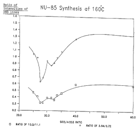
by X-ray powder diffraction. Figure 13 is a plot of relative
intensities of the 10.3 to 11.1 and 3.84 to 3.72 diagnostic
x-ray lines of NU-85 versus the Si02/A1203 ratio of the reaction
mixture. The ratio of the lines at 3.37 to 3.42 is not included
in the plot because the presence o~ an Analcime impurity in some
of the samples masks the true intensity of the line at 3.42.
Examination of Table 11 and Figure 13 shows as the
aluminium content of the reaction mixture is increased, ie the
Si02/A1203 ratio decreases the product has increased NU-85
character, ie the relative intensity of the line at 10.3 to the
line at 11.1'x. and the relative intensity of the line at 3.84$ to
the line at 3.72 decreases.
However, at a Si02/A1203 ratio in the region of about
30 to 32 this trend is reversed and the NU-85 character of the
product decreases. When the Si02/A1203 ratio is in the region of
about 27 to 30 the amount of NU-85 character increases before
again decreasing.
Without being bound by theory, it is believed the
initial decrease in the amount of NU-85 character present in the
product and, indeed, the overall "well-shaped" plot are
associated with the preparation of an Analcime impurity.
Analcime, being an aluminium-rich phase, is believed to act as
"sink" for aluminium with the result that the reaction mixture
has a higher effective Si02/A1203 ratio.
This example demonstrates that the preparation of NU-85
is critically dependant on the aluminium content of the reaction
mixture. If either too much or too little aluminium is present
EU-1 is formed in preference to NU-85.
Example 19
A reaction mixture of molar composition
60 Si02 - 2AI203 - 10 Na20 - 10 Hex Br2 - 3000 H20
was prepared from:
171.7g "SYTON X30" (Monsanto: a colloidal silica sol
containing 30X silica
7.488g Sodium Aluminate (BDH Ltd: 27.85X w/w Na203
34 ~ ~ ~ ~ H35799
38.902 w/w A1203, 33.25% w/w H20)
8.738 Sodium Hydroxide
134.08 HexBr2 solution (Containing 38.6% w/w HexBr2
in water)
565.18 Water
The molar composition given does not include sodium present in
the "SYTON X30"
The mixture was prepared as follows:
A - solution containing the sodium hydroxide and sodium aluminate
in 2508 of water
B - solution containing HexBr2 in 1508 of water
C - dispersion of "SYTON X30" in the remaining water.
Solution A was added to solution B and the resulting
solution added, with stirring, to dispersion C. Stirring was
continued until a smooth gel was obtained. The resulting mixture
was transferred to a 1 litre stainless steel autoclave and
reacted at 170°C, with stirring at 300 rpm using a pitched-paddle
type impeller.
The preparation was sampled periodically after 144
hours at reaction temperature the preparation was crash cooled to
ambient temperature and the product discharged. The product was
filtered, washed with demineralised water and then dried at
110°C.
The product was analysed by X-ray powder diffraction
and identifed as a highly crystalline sample of zeolite NU-85
containing no detectable crystalline impurities. The ratios of
the intensities of the diagnostic XRD lines aces-
Ratio of
intensities
(rounded to
one decimal
Spacing/ Intensities place)
relationship (b) 3.84 vs 3.72 30.15 vs 28.92 1.0
relationship (a) 10.3 vs 11.15 12.61 vs 25.63 0.5
relationship (c) 3.37 vs 3.42 21.36 vs 22.54 0.9
35 ~ ~ la ~ ~ H35799
Table 2 - X-RAY DATA FOR THE PRODUCT OF EXAMPLE 1
dtAngstroms) Relative Intensity
21.02 3.7
11.25 26.3
10.21 18.1
g,82 5.4
6.90 2.8
5.80 3.5
5.64 3.0
4.90 1.2
4.66 37.2
4.34 100.0
4.11 8.8
4.02 55.5
3.83 30.1
3.72 22.4
3.65 3.0
3.60 1.9
3.50 2.5
3.44 14.8
3.36 19.1
3.28 37.4
3.16 4.9
3.09 5.1
3.01 1.6
2.g5 6.6
2.90 1.8
2.70 4.8
36 H35799
2~3~~9~0
'Fable 3 - X-RAY DATA FOR THE PRODTJCT OF EXAMPLE 2
d(Angstroms) Relative Intensity
11.16 23.7
10.17 14.1
9,77 4.0
6.87 1.8
5.78 3.0
5.60 2.3
4.67 33.8
4.33 100.0
4.01 61.4
3.83 37.5
3.72 29.6
3.65 4.6
3.44 18.2
3.43 20.3
3.37 22.7
3.28 52.6
3.26 46.5
3.25 37.4
3.16 7.9
3.15 7.5
3.10 8.5
2.95 10.1
2.94 8.6
2.89 3.5
2.81 1.9
2.76 1.9
2.71 7.3
2.70 7.7
37 ~ ~ ~ ~ H35799
Table 4 - X-RAX DATA FOR THE PRODUCT OF EXAMPLE 3
d(Angstroms) Relative Intensity
11.16 31.5
10.24 12.2
6.88 2.1
5.78 2.4
5.59 3.0
4.67 33.3
4.64 26.0
4.33 100.0
4.02 58.3
3.85 22.6
3.83 20.3
~5 3.72 23.0
3.43 19.3
3.37 20.9
3.29 47.0
3.29 54.8
2p 3.26 37.1
3.16 4.8
3.10 5.9
2.95 5.1
2.71 4.5
38 ~ ~ ~ ~ 635799
Table 5 - X-RAY DATA FOR THE PRODUCT OF EXAMPLE 4
d(Angstroms) Relative Intensity
11.13 32.0
10.19 11.8
6.87 2.4
5.77 2.5
5.56 2.7
4.90 1.3
4.66 34.8
4.64 30.6
4.33 100.0
4.01 67.7
3.84 27.7
3.73 29.5
3.71 30.1
3.43 24.1
3.37 23.6
3.35 23.4
3.28 59.6
3.25 39.6
3.16 7.9
3.09 8.7
2.93 7.6
2.70 6.4
3g H35799
2(~~~~f~~
Table 6 - X-RAY DATA FOR THE PRODt7CT OF EXAMPLE 5
d(Angstroms) Relative Intensity
11.09 27.6
10.16 13.5
10.08 12.5
6.85 2.2
5.74 2.7
5.57 2.3
4.66 33.3
4.32 100.0
4.01 63.2
3.84 32.2
3.82 28.9
3.72 30.6
3.44 20.4
3.43 22.1
3.36 23.7
3.27 57.4
3.15 7.7
3.10 8.8
2.94 8.9
2.80 1.7
2.70 6.8
40 H35799
Table 7 - X-RAY DATA FOR THE PRODUCT OF EXAMPLE 6
i:
d(Angstroms) Relative Intensity
11.07 26.3
10.13 15.0
10.00 11.6
9.69 4.8
6.84 1.9
5.76 3.7
5.58 2.8
4.65 34.4
4.32 100.0
4.01 60.3
3.82 34.5
3.71 24.7
3.64 1.1
3.43 17.7
3.36 21.4
3.28 46.7
3.27 53.4
3.25 43.5
3.15 5.0
3.09 5.8
2.95 7.2
2.89 1.1
2.71 6.0
41 ~ ~ ~ ~ ~ H35799
Table 8 - X-RAY DATA FOR THE PRODUCT OF EXAMPLE 9
d(Angstroms) Relative Intensity
11.20 33.2
10.39 10.5
6.89 2.5
5.58 13.1
4.67 34.6
4.34 100.0
4.02 718
3,gg 20.0
3.85 20.0
3.73 31.9
3.72 23.4
3.42 37.4
3.37 23.5
3.28 64.1
3.26 44.8
3.17 6.1
3.10 8.7
2.91 13.1
2.71 5.6
42 H35799
Table 9 - X-RAY DATA FOR THE PRODUCT OF EXAMPLE 10
d(Angstroms) Relative Intensity
11.13 27.3
10.26 93
6,gg 2.4
6.32 2.9
5.57 9.1
4.66 33.5
4.33 100.0
4.02 69.1
3.84 23.8
3.73 33.4
3.71 27.5
3.65 20.5
3.43 38.0
3.37 27.0
3.28 67.3
3.26 52.8
3.17 11.2
3.10 11.3
3.09 10.2
2.91 12.1
2.84 4.1
2.79 2.5
2.71 7.7
_43_ H357R9
a~
.C
a~
11 M G,
of ~D Id
N
W N v0
C
rl r-I
~c,' m c0 o b U N
W O rl fn
N
~
.,.~ 1~
Ii N O
ra r-I
N ri c0
i~
~
v C
1
~ x C
~
C
W c
d
U U
'~
O
N 'i
~ ~
La N O
N
ut
td r-i Ov t0 t~ '~
.-1 N ri I~
OD t M
r" N
GL r1 O rl O O C:' G -
ri r-I rl O
1 o-i
m p, . . . a . . .rl cn N
,..1 . . .
~
Op C, O O O O O rl 41 eA t~
4-1 O O O O
N N 1-I O
1 1~ fly 4i
W
, a0 W a1
0
a C v
~ o
~n d
rY, M N rl M M td O
M t0 CO CO
CY1
A td n OD OD W Is1 '~," O
CO o~ rn
o
0 0 O o 0 0 ~
o rl 0
W
0 0 0 0 0 0 ,.1 .N on
o 0 0
~ O ~
W o
p~, U W O ri
p rl N .f.~
v~ cd r Ia
U T3 N
1 d N O N W
y
O r Id 41 N
i ~
~
r-1.In cJ1 '-I N h $ 4-t 'n .yJ
O 'i N rn
N o0
of rl rl ..i ~n ~d
v~ m m m ~
P, In ~
,a . . . d p ~ ,ta
~
w
N 000 QOO 000 W
HLL
~ r
~ x
~
~
tn
H
ri ..
3
4-I N 'N
L.t O N O
N ~ ly,"
CSO i~ cd U N
v a1 N C Cj
ai $~ b0
N '.~ ~ .
O P, N N N t7 ~f-1
~-
O
b N N
o 'd N '.l~
a; Id r1 C N
H
G. .IJ U e-1 +~
(3, (3, rl tSi ~
~ W+~ y a
p o
~
G ~ ~b
~~
p) id N U~ H a1 ,"C, H H
cd p. Q1 O
N ~ r-I
Lt ,'T~ ,-i U
O I O P.
cn p H U .-I N cn
o m o
L h v- - N
44 H35799
204~~~0
U
N
N to l~ ~ t~ N t~
3 ~ o ~ M ~ 0 0 0 0 0 0
rl
3
N
v n o ~on a, o~ o, o ~ M M
M
,_.jo 0 0 0 0 ~-I~-Irl ri
rl
o
M
0
G
0 0
rl
r1
+1 .N ty t M M vt 3' a ~' Y1 v0 vO
rl
N O 'd Pa O O O O O O O O O O O
M
O N N
P. x1>-~ 4
O ~
O .
1
U O d-~
O N
~L.~M
o G
I ..~
tn N
N N U N
N y o ' ~ M M O N O~ ~D N M a O N
~
, O tti, M 00 M M vt I ri W t0
G4 ~
,N .~~p,...1y7. M M vY~' ~' M M N N N .rI
O tdO
U ~ M
'i i O r-1O
s~ O N N ~ vttn u7 et)en
U O 91 ' ' '
N d f M tO W OD O '-IN M u7 O O
t
O tdN . '~ N N N N M M M M M ~ ~O
fn
1..~'Ir~
S v~ O
-~
O r-1M N t!)
i.i U rf
4a I F''
N r1
~ X 0 0 ~ ~
3 v, 00 0
,
rl r1 t N ri.-1 ~ a0 n 1~ tn
l - W 1 01
-i N
.-IN DC N N N N N rl ri r r e
~ fa
N
N
O I 4'r1
~ . ~ 1
'' E~
F
e N tw d -
-i
~
~ O ~ N
W W W
O ~
riO
~
H ~ 6 -f W a W U ~1 W W Ch xl H h PG ~k
C ' -
k
, . ,
r N
45 H357~9
Table 12° NU-85 Pre~aration~ 1 and 2 litre autoclaves
Composition(1) Reagents(2) Temp Time X Analcime
60,1.000,10,10,3000 Si02, SA,Soln160 142 0
60,1.500,10,10,3000 Si02, SA,Soln160 240 0
60,1.714,10,10,3000 Si02, SA 160 264 0
60,1.791,10,10,3000Si02, SA,Soln160 263 0.7
60,1.846,10,10,3000 S302, SA,SOIn160 312 0.2
60,1.905,10,10,3000 Si02, SA,Soln160 316 0.7
60,2.000,10,10,3000 Si02, SA 160 449 4.4
60,2.105,10,10,3000 Si02, SA9Soln160 432 3
60,2.280,10,10,3000Si02, SA,Soln160 450 4.7
60,2.264,10,10,3000 Si02, SA,Soln160 383 10.6
60,2.4, 10,10,3000 Si02, SA 160 333 16.2
Notes: (1) Composition ~ Si02, A1203, Na20, HexBr2, H20
(2) Reagents: Si02 ="SYTON X30" (BDH); SA = Sodium Aluminate (BDH);
Soln = HexBr2 solution
otherwise solid HexBr2 was used
H35799
The invention also provides a catalyst composition
comprising zeolite NU-.85 and catalytic processes employing
zeolite NU-85 as a catalyst.
In the catalysts accarding to the invention X02 is
preferably silica and Y20g is preferably alumina. Such catalysts
may be used in a wide variety of catalytic processes and using a
wide variety of feedstocks.
Catalytically useful forms of zeolite NU-85 include the
hydrogen and ammonium forms, prepared by the methods hereinbefore
described.
Catalysts according to the invention comprising NtJ-85
may also comprise one or more elements, especially metals or
rations thereof, or compounds of said elements, especially metal
oxides. Such catalysts may be prepared by ion-exchange or
impregnation of zeolite I5U-85 with. the said element, ration or
compound, or a suitable precursor of said ration or compound.
Such ion-exchange or impregnation may be carried out on the
"as-prepared" zeolite NU-85, the calcined form, the hydrogen form
andJor the ammonium form and/or any other exchanged form.
In cases where a metal-containing form of zeolite NU-85
is prepared by ion-exchange it may be desirable to effect
complete exchange of the metal, by which is meant that
substantially all of the exchangeable sites are occupied by the
metal. Such forms may be particularly useful in separation
process, for example the separation of xylenes. In most cases,
however, it is preferable to effect only partial exchange of the
metal, the remaining sites being occupied by another ration
especially hydrogen or ammonium rations. In some cases it may be
desirable to introduce two or more metal rations by ion exchange.
In cases Where zeolite NU-85 is impregnated with a
metal compound to form a catalyst, the metal compound may be
added in any suitable quantity, but 20X by weight is generally
sufficient for most applications; for some applications up to lOX
by weight is sufficient, and quantities of up to 52 axe often
appropriate. Impregnation may be carried by any suitable method
known in the art of catalyst preparation.
HS5799
2a449~~
Metal-exchanged forms or forms in which a metal
compound has been impregnated may be used as such or they may be
treated to produce an active derivative. Treatments include
reduction, for example in an atmosphere comprising hydrogen, to
produce a metal or other reduced forms. Such treatments may be
carried out at a suitable stage in the catalyst preparation or
may conveniently be carried out in the catalytic reactor.
Catalytic compositions comprising zeolite NU-85 can, if
desired, be associated with an inorganic matrix which may be
either inert or catalytically active. The matrix may be present
solely as a binding agent to hold the zeolite particles together,
possibly in a particular shape or form, for example as a pellet
or extrudate, or it may function as an inert diluent, for example
to control the activity per unit weight of catalyst. When the
inorganic matrix or diluent is itself catalytically active it can
thereby form an effective part of the zeolite/matrix catalyst
composition. Suitable inorganic matrices and diluents include
conventional catalyst support materials such as silica, the
various forms of alttmina, clays such as bentonites,
20 montmorillonites, sepiolite, attapulgite, Fullers Earth and
synthetic porous materials such as silica-alumina,
silica-zirconia, silica-thoria, silica-beryllia or
silica-titania. Combinations of matrices are contemplated within
the present invention, especially combinations of inert and
25 catalytically-active matrices.
When zeolite NU-85 is associated with an inorganic
matrix material or a plurality thereof, the praportion of matrix
material or materials in the total composition usually amounts to
up to about 90X by weight, preferably up to 50X by weight, more
30 preferably up to 30X by weight.
For some applications another zeolite or molecular
sieve may be used in conjunction with zeolite NU-85 to form a
catalyst. Such a combination may be used as such or associated
with one or more matrix materials hereinbefore described. A
35 particular example of the use of such an overall composition is
as a fluid catalytic cracking catalyst additive, in which case
48 H35799
2fl4~fl~fl
zeolite NU-85 is preferably used in an amount of 0.5 to 5X by
weight of the total catalyst.
For other applications zeolite NU-85 may be combined
with another catalyst, such as platinum on alumina.
Any convenient method of mixing zeolite NU-85 with an
inorganic matrix and/or another zeolite material, may be
employed, especially that suited to the final form in which the
catalyst is used, for example extrudates, pellets or granules.
If zeolite NU-85 is used to form a catalyst in
conjunction with a metal component (for example, a
hydrogenation/dehydrogenation component or other catalytically
active metal) in addition to an inorganic matrix, the metal
component can be exchanged or impregnated into the zeolite NU-85
itself before addition of the matrix material or into the
zeolite-matrix composition. Far some applications it may be
advantageous to add the metal component to the whole or part of
the matrix material before mixing the latter with the zeolite
NU-85.
A wide range of hydrocarbon conversion catalysts
comprising zeolite NU-85 can be prepared by ion-exchange or
impregnation of the zeolite with one or more cations or oxides
derived from elements selected from Cu, Ag, Ga, Mg, Ca, Sr, Zn,
Cd, B, Al, Sn, Pb, V, P, Sb, Cr, Mo, W, Mn, Re, Fe, Co, Ni and
noble metals.
, In cases where catalysts comprising zeolite NU-85
contain one ox more hydrogenation/dehydrogenation components such
as the metals Ni, Co, Pt, Pd, Re and Rh, such components can be
introduced by ion-exchange or impregnation of a suitable compound
of the metal.
Catalyst compositions comprising zeolite NU-85 may find
application in reactions involving saturated and unsaturated
aliphatic hydrocarbons, aromatic hydrocarbons, oxygenated organic
compounds and organic compounds containing nitrogen and/or
sulphur as well as organic compounds containing other functional
groups.
4g H35799
~~~4~~~
In general, catalyst compositions comprising zeolite
NU-85 can be usefully employed in reactions involving
isomerisation, transalkylation and disproportionation, alkylation
and de-alkylation, dehydration and hydration, oligomerisation and
polymerisation, cyclisation, aromatisation, cracking,
hydrogenation and dehydrogenation, oxidation, halogenation,
synthesis of amines, hydrodeaulphurisation and
hydrodenitrification, ether formation and synthesis of organic
compaunda in general.
The above processes may be carried out in either the
liquid or vapour phase under conditions which are chosen as
suitable for each individual reaction. For example, the
reactions carried out in the vapour phase may involve the use of
fluid bed, fixed bed or moving bed operations. Process diluent~
may be used when required. Depending upon the particular
process, suitable diluents include inert gases (such as nitrogen
or helium), hydrocarbons, carbon dioxide, water or hydrogen. The
diluent may be inert or it may exert a chemical effect. It may be
an advantage, especially in cases where hydrogen is used, to
include a metal component, such as a hydrogenation)
dehydrogenation component, for example one or more of the metals,
Ni, Co, Pt, Pd, Re or Rh as part of the catalyst composition.
According to a further. aspect of the present invention
we provide a hydrocarbon conversion process which comprises
contacting an alkylbenzene or a mixture of alkylbenzenes under
isomerisation conditions in the vapour or liquid phase with a
catalyst comprising zeolite NU-85.
Isomerisation reactions for which catalysts comprising
zeolite NU-85 are of particular use are those involving alkanes
and substituted aromatic molecules, especially xylenes. Such
reactions may include those which can be carried out in the
presence of hydrogen. Catalyst compositions containing zeolite
NU-85 which are of particular use in isomerisation reactions
include those in which the NU-85 is in its acid (H) form,
cation-exchanged form, or other metal-containing forms or
combinations thereof. Especially useful are those forms in which
50 H35799
the metal is a hydrogenation/dehydrogenation component such as
Ni, Co, Pt, Pd, Re or Rh.
Particular isomerisation reactions in which a catalyst
comprising NU-85 may be found useful include xylene isomerisation
and hydroisomerisation of xylenes, paraffin, in particular C4 to
Clp normal hydrocarbons, or olefin isomerisation and catalytic
dewaxing.
Xylene isomerisation and hydroisomerisation may be
carried out in the liquid or vapour phase. In the liquid phase,
suitable isomerisation conditions include a temperature in the
range 0-350°C, a pressure in the range 1-200 atmospheres
absolute, preferably 5-70 atmospheres absolute, and when
conducted in a flow system, a weight hourly space velocity (WHSV)
preferably in the range 1-30 hr-1 based on the total catalyst
composition. Optionally, a diluent may be present, suitably one
or more of those having a critical temperature higher than the
isomerisation conditions being used. The diluent, if present,
may comprise 1-90X by weight of the feed. Vapour phase xylene
isomerisation and hydroisomerisation reactions are most suitably
carried out at a temperature in the range 100-600°C, preferably
200-500°C, at a pressure in the range 0.5-100 atmosphere
absolute, preferably 1-50 atmospheres absolute, and at a WHSV up
to 80 based on the total catalyst composition.
When xylene ieomerisation is conducted in the presence
of hydrogen (in the vapour phase), the preferred
hydrogenation/dehydrogenation component is Pt or Ni. The
hydrogenation/dehydrogenation component is usually added in an
amount of between 0.05 and 2X by weight of the total catalyst.
Additional metals and/or metal oxides may be present in the
catalyst composition.
In xylene isomerisation, ethylbenzene may be present in
the xylene feed in amounts up to 401 by weight. Over catalyst
compositions comprising zeolite NU-85 the ethylbenzene will
undergo transalkylation with itself, and with xylenea, to form
heavier and lighter aromatic compounds. The ethylbenzene will
also react to form benzene and light gas, particularly at
51 ~ ~ ~ ~ ~ H35799
temperatures above 400°C. With such xylene feeds containing
ethylbenzene, when reaction is carried out in the presence of
hydrogen over a catalyst composition comprising zeolite NU-85
together with a hydrogenation/dehydrogenation component, some of
the ethylbenzene will isomerise to xylenes. It may also be an
advantage to carry out xylene isomerisation reactions in the
presence of a hydrocarbon compound, especially a paraffin or
naphthene with or without the additional presence of hydrogen.
The hydrocarbon appears to improve catalyst performance in that
reactions which lead to xylenes loss are suppressed and,
particularly when reactions are carried out in the absence of
hydrogen, catalyst life is extended.
According to yet a further aspect of the present
invention we provide a hydrocarbon conversion process which
comprises contacting one or more alkylated aromatic compounds
under transalkylation conditions in the vapour or liquid phase
with a catalyst comprising zeolite NU-85.
Catalysts comprising zeolite NU-85 are of especial
value in transalkylation and disproportionation reactions, in
particular those reactions involving mono.-, di-, tri- and
tetra-alkyl substituted aromatic molecules, especially toluene
and xylenes.
Catalyst compositions comprising NU-85 which are of
particular use in transalkylation and disproportionation reaction
include those in which the NU-85 component is in its acid (H)
form, its cation-exchanged form, or other metal-containing forms
or combinations thereof. Especially useful is the acid form and
those forms in which the metal is a hydrogenation/
dehydrogenation component such as Ni, Co, Pt, Pd, Re or Rh.
Particular examples of important processes include
toluene disproportionation and the reaction of toluene with
aromatic compounds containing 9 carbon atoms, for example
trimethyl benzenes.
Toluene disproportionation can be conducted in the
vapour phase either in the presence or absence of hydrogen,
although the presence of hydrogen is preferred as this helps to
52 H35799
2~4~~~0
suppress catalyst deactivation. The most suitable reaction
conditions are: temperatures in the range 250-650°C, preferably
300-550°C; pressures in the range 0.3-100 atmospheres absolute,
preferably 1-50 atmospheres absolute; weight hourly space
velocity up to 50 (based on the total catalyst composition).
When toluene disproportionation is conducted in the
presence of hydrogen the catalyst may, optionally, contain a
hydrogenation/dehydrogenation component. The preferred
hydrogenation/dehydrogenation component is Pt, Pd, or Ni. The
hydrogenation/dehydrogenation component is normally added in a
concentration of up to 5X by weight of the total catalyst
composition. Additional metals and/or metal oxides may be present
in the catalyst composition, for example up to 5X by weight of
the total catalyst, composition.
The present invention further provides a hydrocarbon
conversion process which comprises reacting an olefinic or
aromatic compound with a suitable alkylating compound under
alkylating conditions in the vapour or liquid phase over a
catalyst comprising zeolite NU-85.
Among the alkylation reactions for which catalysts
comprising zeolite NU-85 are of particular use are the alkylation
of benzene or substituted aromatic molecules with methanol or an
olefin or ether. Specific examples of such processes include
toluene methylation, ethylbenzene synthesis, and the formation of
ethyl toluene end cumene. Alkylation catalysts used in processes
according to this further aspect of the invention may comprise
further materials, especially metal oxides which may improve
catalytic performance.
Catalysts comprising zeolite 1~IU-85 may find application
in reactions involving the dehydration of alcohols, for example
methanol and higher alcohols, to form hydrocarbons, including
olefins and gasoline. Other feedstocks for dehydration reactions
involving a catalyst Comprising NU-85 include ethers, aldehydes
and ketones.
By the use of a catalyst comprising NU-85, hydrocarbons
can be generated by carrying out oligomerisation, cyclisation
53 ~ ~ ~ ~ ~ H35799
andJor aromatisation reactions on unsaturated compounds such as
ethene, propene or butene, on saturated compounds such as propane
or butane or mixtures of hydrocarbons such as light naphthas.
For some reactions, particularily aromatisation'reactions, the
catalyst may usefully comprise a metal or metal oxide, especially
platinum, gallium, zinc or their oxides.
Catalysts comprising NU-85 are of use in a variety of
cracking reactions, including the cracking of olefins, paraffins
or aromatics or mixtures thereof. Of particular value is the use
of zeolite NU-85 as a fluid catalytic cracking catalyst additive
to improve the product of the cracking reaction. Zeolite NU-85
may also be used as a component of a catalyst in catalytic
dewaxing or hydrocracking processes.
Hydrogenation/dehydrogenation processes, for example
the dehydrogenation of alkanes to the corresponding olefins, are
suitably carried out by contacting the appropriate feedstock
under appropriate conditions with a catalyst comprising zeolite
NU-85, especially when the latter also comprises a
hydrogenation/dehydrogenation component such as I3i, Co, Pt, Pd,
Re or Ru.
Zeolite NU-85 is useful as a component in a catalyst
for the preparation of amines, for example the production of
methylamines from methanol and ammonia.
Zeolite NU-85 is also a useful catalyst for the
formation of ethers, particularly by the reaction of two alcohols
or by the reaction of an olefin with an alcohol.
The invention relating to catalysts comprising NU-85
and processes using these catalysts is illustrated by the
following Examples.
Example 20: Dispro~portionation of Toluene
A portion of the product from Example 13 was compacted
into aggregates of a size within the range 425 and 1000 microns.
lg of this material was placed in a 4mm internal diameter
stainless steel reactor and calcined at 500°C in air for 16 hours
at atmospheric pressure. The air was replaced by nitrogen and
the reactor and contents were cooled to 350°C. Hydrogen was then
54 H35799
passed through the reactor and the pressure raised to 2069 kPa.
The hydrogen flow rate Was set at 1728cm3 per hour as measured at
atmospheric pressure. After 1 hour, toluene was introduced into
the hydrogen stream at a rate of 1.9m1 of liquid per hour. The
mole ratio of hydrogen to toluene was 4 to 1 and the weight of
toluene per unit weight of solid was 1.64. The reaction was
continued for 7 days during which the temperature was increased
stepwise in order to maintain 47X conversion of the toluene.
This procedure was repeated with a portion of material
from Examples 14, 15 and 16B. (* A portion of the final product
from Example 12 was activated by a procedure similar to that
described in Example 17 and also tested.) The composition of the
product from the tests after a reaction time of 150 hours is
given below in Table 13.
Table 13
Example Temp Wt% products at 471 conversion
°C Gas Benzene Ethyl- Xylenes Cg
Benzene Aromatics
13 382 0.2 19.9 0.1 23.8 3.2
14 409 0.3 20.4 0.2 22.9 3.2
15 359 0.1 19.5 0,1 24.2 3.1
16B 366 0.2 19.9 0.1 23.5 3.0
12* 390 0.8 20.2 0.2 22.7 3.1
The results in Table 13 show that the three samples
tested have different activites in toluene disproportionation as
i ~ icated by the temperature required to give 47Z conversion.
Table 14 and Figure 14 compare the activity of the
above samples of zeolite NU-85 in toluene disproportionation, as
measured by the temperature required to give 47X conversion,
CA 02044960 2000-04-OS
against the ratio of the intensity of the XRD line at
3.86+/- 0.08 A t;o the: intensity of the line at 3.71 +/-
0.07 A.
TABLE 14
Example Intensitzrof the Ratio of intensity Temp required
lines /A of lines 3.86 to to give 47%
3.7
(to one decimal conversion
place) /C
3. 86 + 0.08 3.77_ 0.07
13 27.7 30.1 0.9 382
14 32.2 30.6 1.1 409
15 20.0 31.9 0.6 359
16B 23.8 33.4 0.7 366
12* 29.9 29.0 1.0 290
The linear nature of the plot illustrates that
there is a diz-ect :relationship between the catalytic
10 performance of zeolite NU-85 and relative intensities of
characteristic lines in the XRD of the samples. This
provides further evidence that zeolite NU-85 is a family of
materials.
Example 21 Crackina of n-butane
The cz-acking of n-butane over H-NU-85 was
examined using a portion of the material from Example 16.
The procedure fo7_lowed that described by . H Rastelli Jr. ,
BM Lok, J A Dui:~man, DE Earls and JT Mullhaupt, Canadian
Journal of Chemical Engineering, Volume 60, February 1982,
20 pages 44-49.
A portion of the product from Example 16 was
pelleted, broken down and sieved to give a 500-1000 micron
CA 02044960 2000-04-OS
56
size fraction. 0.268c~ of this material was charged to a
stainless-steel micro reactor (internal diameter 4.6 mm)
and supported on glass wool and glass balls. The material
was then dehydrated "in situ" by heating at 500°C for 5.5
hours in a stream of airy nitrogen.
A feed containing 2.19% v/v n-butane, 15.36% v/v
nitrogen and 82.45% vfv helium was passed over the catalyst
bed. The cataly:~t bed was maintained at a temperature of
500°C and atmospheric pressure. The cracked products were
analysed by gas chromatography. This showed that the
zeolite cracked n-butane to C1-C3 hydrocarbons. At a feed
flow rate of 50.0 cm3 per minute a n-butane conversion of
37.0% was measured. This corresponds to a kA of 85 cm3/g
min using the equation given in the above reference.
The zeolite was the regenerated by heating at
500°C for 5 hours i.n a stream of air. The feed was
reintroduced at <~ feed flow rate of 49.6 cm3 per minute and
a n-butane conversion of 32% was measured. This corresponds
to a kA of 72 cm-3/g mi:n.
2~~ This e~xamplE, shows that zeolite NU-85 is an
active catalyst i_or n-butane cracking.
Examples 22 Fluid Catalytic Crackincr Additive
ZeolitE~ NU-8.5 was evaluated as a fluid catalytic
cracking (FCC) a<iditiv~~ by adding it in small quantities to
a base FCC catalyst and then monitoring its effect on the
cracking product:> in a microactivity test (MAT) run.
Base Ca~talYst
The base FCC catalyst used was Resoc-1 E-Cat*
(Grace Davidson). The "E-Cat" indicates that the catalyst
30 has been deacti~rated on line in a FCC plant. The base
* trademark
CA 02044960 2000-04-OS
56a
catalyst was decoked by calcining in air for 24 hours at
550°C. Resoc-1 is a rare earth exchange Ultrastabilised Y
zeolite based cat;alyst in spray dried form.
Additive Catalyst
The sample of NU-85 was tested by preparing a
catalyst comprising Rc=soc-1, E-Cat + 1% by weight fresh
NU-85 based on t~ze weight of Resoc-1, E-Cat. (The % weight
of NU-85 was based on anhydrous material)
Individual catalysts were prepared by thorough
physical mixing of the base catalyst with a portion of
material from
57 H35799
2044960
Example 16. The mixture was then compressed. The resulting
pellet was broken up and sieved to give granules with a size in
the range of 44 to 70 microns.
The feedstock used in these experiments was Cincinnati
gas oil. The properties of this material are as follows.
Vacuum Distillation °C
lOX at 760 mm 312.7 (595°F)
30X 362.8 (685°F)
50X 407.2 (765°F)
70X 451.7 (845°F)
80X 501.1 (934°F)
The MAT runs were carried out in a fixed bed unit using
a 0.8978 charge of Cincinnati gas oil and 2.58 of catalyst. The
contact time was 80 seconds. The weight hourly space velocity
(WHSV) of individual runs is given in Table 15.
The catalyst samples had all been calcined in air at
538°C (1000°F) for 1 hour before testing. The starting
temperature for each run was 515.6°C (960°F).
The products were analysed by gas chromatography
capillary column analysis from which the research actane number
(RON) of the resulting gasoline could be determined. Table 15
lists this data.
From results given in Table 15 it can be seen that the
addition of zeolite NU-85 increased the yield of C3 and C4
paraffins and olefins, although this is at the expense of a
reduced gasoline yield. The overall FCC gasoline and alkylate
yield was essentially unchanged. The zeolite NU-85 addititve
increased the RON of the gasoline by two points. Analysis of the
gasoline showed that this was mainly due to an increased
concentration of the C6 to Cg aromatics (benzene, toluene,
ethylbenzene and xylenes).
Example 23: Hydroisomerisation of n-Pentane
A slurry consisting of 20.208 of the material from
Example 16, 8.30m1 of a chloroplatinic acid solution and 50 ml o~
58 H35799
deionised water was stirred in a closed vessel at room
temperature for 4 hours. (The chloroplatinic acid solution
contained the equivalent of 0.340g of platinum in 25 ml of
deionised water). Water was then evaporated from the mixture
using a rotary evaporator and the resultant solid calcined in
air at 500°C for 3 hours.
The platinum impregnated zeolite powder thus produced
was analysed by Atomic Adsorption Spectroscopy (AAS) and found to
contain 0.41 weight per cent platinum. The powder was pelleted,
broken-down and sieved to give a 500 to 1000 micron size
fraction.
1.16g of this material was transferred to a stainless
steel reactor (internal diameter 4.2 mm) and reduced under a
stream of hydrogen at 250°C and a pressure of 420 psig for 19
hours. Ziquid n-pentane, which had previously been dried over a
molecular sieve, was vaporised and mixed with hydrogen gas to
produce a mixture with a molar ratio of H2 to pentane of 1.6:1.
This mixture was passed over the catalyst bed at a weight hourly
space velocity (WHSV) of 0.9 hour -1 (based on the n-pentane) at
a pressure of 437 psig and a temperature of 251°C. The product
leaving the reactor bed was analysed by on line chromatography.
It was found to contain 61X isopentane and 39X n-pentane. This
corresponds to a conversion of 61X.
Since the maximum conversion possible at 251°C is 72X,
ie the limiting theranodynamic equilibrium mixture of n-and
iso-pentane,the high conversion achieved with the Pt-Nt1-85
catalyst demonstrates its high activity in n-pentane
hydroisomerisation.
Example 24 : Preparation of Amines
A portion of material from Example 16 was pelleted,
broken down and sieved to give a 500-1000 micron size fraction.
A sample of this material (2.91g) was charged to a tubular
stainless steel microreactor and heated to 180°C under a flow of
nitrogen before ammonia was introduced. After further heating to
300°C, methanol was introduced and conditions were adjusted to
give the desired methanol conversion. The reaction products were
59 H35799
2~449~~
measured by on-line gas chromatography and found to consist of a
mixture of mono-, di- and tri-methylamines. After two days on
stream, at a temperature of 330°C and using a feed containing a
molar ratio of ammonia to methanol of 2 at a gas hourly space
velocity (GHSV) of 1100 hr-1 the methanol conversion was 99X and
the product consisted of 38 moleX monomethylamine, 26 moleX
dimethylamine and 36 molel trimethylamine.
This example demonstrates the use of zeolite NU-85 as a
catalyst for the preparation of amines.
Example 25: Tsomerisation of Xvlenes
A portion of the material from Example 16A was
pelleted, broken down and sieved to give aggregates of between
425 and 1000 microns in size. 0.5g of the aggregates were placed
in a 5mm internal diameter stainless steel tubular reactor and
calcined in air for 16 hours at 500°C and at atmospheric
pressure. The air was purged with nitrogen and the reactor and
contents Were cooled to 300°C.
A mixture of C8 aromatic hydrocarbons was pumped into a
vaporiser and then through the reactor at 300°C and atmospheric
pressure. The rate was initially 10 ml of liquid per hour. The
product was analysed regularly. After 24 hours the temperature
was increased to 360°C and the feed rate reduced to 5.0 ml per
hour. As the conversion fell, the temperature was further
increased.
The feed and product compositions obtained axe given in
Table 16.
The results show that NU-85 catalyses the isomerisation
of xylenes with only small xylenes losses, particularly at
temperatures above 400°C. Ethylbenzene loss, which is desirable
for efficient xylenes isomerisation plant operation, was quite
high.
Exa dole 26: Methy_lation of Toluene
The sample of zeolite NLT-85 (0.5g) used in the previous
example and still in the tubular reactor was calcined in air at
500°C for 16 hours. The reactor was then purged with nitrogen as
it was cooled to 300°C.
60 H35799
~044~~~
A mixture of toluene and methanol, in a mole ratio of 3
to 1, was pumped through the reactor at a temperature of 300°C
and atmospheric pressure.
The composition of the aromatic compounds in the
product at various times is given in Table 17.
Example 27: Ethvlation of Benzene
The sample of zeolite NU-85 (0.5g) used in the previous
example and still in the tubular reactor was calcined in air at
500°C for 16 hours. The reactor was then purged with nitrogen
and cooled to 350°C.
A mixture of benzene and ethylene, in a mole ratio of 3
to l, Was pumped through the reactor at 300°C and 20 Bar
pressure.
The composition of the product at various times and
temperatures is given in Table 18.
It is clear from the results that overall selectivity
to ethylbenzene is high. No xylenes, which would be difficult to
remove from the product, were detected.
Examyle 28: Hydroisomerisation of Xylenes
A sample of the material from Example 16A was pelleted,
broken down and sieved to give aggregates of between x+25 and 1000
microns in size. O.lg of the aggregates were placed in a 3mm
internal diameter stainless steel reactor and calcined in air for
16 hours at 500°C and atmospheric pressure. The air was purged
with nitrogen and the reactor and contents cooled to 330°C.
Hydrogen was then introduced into the reactor and the pressure
allowed to increase to 6.7 bar. The ~low of hydrogen through the
reactor was then set at 4.52 litres per hour.
A mixture of C8 aromatic hydrocarbons was added to the
hydrogen stream at a rate of 5.70 m1 of liquid per hour. (The
mole ratio of hydrogen to hydrocarbon was 4 to l.) The product
was analysed regularly. The temperature was increased stepwise
as the conversion fell.
At the end of the test the hydrocarbon feed rate had
doubled whilst the hydregen feed-rate remained unchanged.
gl ~ ~ ~ ~ ~ H35799
19.
The feed and product compositions are given in Table
Example 29~ Propane Aromatisation
1.73g of the material from Example 16 was stirred with
16 ml of a 7 x 10'3 M solution of Ga(N03)3 at 80°C for 3 hours.
Water was removed by rotary evaporation. The resulting powder
was analysed by AAS and found to contain 0.4X by weight of
gallium. The powder was pelleted, broken down and sieved to give
a 500 to 1000 micron size fraction. 0.45g of this fraction was
then calcined in a stainless steel tubular reactor, under a
stream of dry air, at a rate of 1.5 litres per hour, at 532°C for
3 hours.
A feed of propane gas in nitrogen (29X propane) was
passed over the calcined material at a pressure of 1.5 psig
propane and a weight hourly space velocity of 1.95 hr-1. The
temperature was 532°C. The resulting gaseous products were
analysed by gas chromatography. A gas analysis after 13 minutes
on line at reaction temperature showed that 21X of the propane
feed had been converted. In the gaseous hydrocarbon products,
the concentration of benzene was 14.5 wtX, of toluene 14.5 wtX,
and of xylene isomers 1 wtX. Therefore, the total concentration
of aromatics in the gaseous hydrocarbon products was 30 wtX.
This example demonstrates the use of a gallium
impregnated zeolite NU-85 in the aromatisation of propane.
62 ~ ~ ~ ~ ~ ~ H35799
Table 15: Fluid Catalytic Cracking Additive
Catalyst (Comparative)
Resoc-1, E-CAT
WHSV (hr-1) 15.74 15.98
Temperature : Starting515.6C 515.6C
. Lowest 501.1C 495.6C
WtX Wt%
Conversion 63.23 65.45
Product Yields
Total C3's 4.44 6.00
Propane 0.84 1.29
Propylene 3.60 4.71
Total C4's 8.40 11.02
I-Butane 3.45 4.83
N-Butane 0.67 0.80
Total Butenes 4.29 5.38
1-Butene 2.01 2.78
Trans-Butenes 1.31 1.50
Cis-Butenes 0.96 1.10
BP range C5_
430F Gasoline 44.11 40.76
BP range 430-
650F Light Cycle
Gas Oil 22.43 21.04
BP range 650F and
above Diesel Oil 14.34 13.51
FCC Gasoline + Alkylate
(VOL %) 76.83 78.86
Research Octane Number
(Gasoline) 93.3 95.3
BP=boiling point
63 H3S799
Table 16 Isomerisation Xylenesover
of NU-85
feed product
composition
(wt%)
Time (hr) 10 71 96 151
Temperature 300 330 360 400
(C)
Feed Rate (ml/h) 10.0 5.0
Gas (wt%) 0.01 0.00 0.00 0.01
Benzene (wt%) 0.17 0.37 0.38 0.26 0.27
Toluene (wt%) 1.03 5.47 6.76 2.58 2.22
Non Arom (wtX)0.08 0.08 0.08 0.08 0.08
E Benzene (wt%)3.96 2.77 2.50 3.52 3.61
P Xylene (wt%)11.89 18.85 19.11 20.96 21.36
M Xylene (wt%)56.08 46.36 44.88 48.48 48.45
0 Xylene (wtX)25.55 19.56 18.17 21.48 21.40
C9+ Arom (wtX)1.26 6.53 8.11 3.04 2.60
% P Xylene 6.96 7.22 8.67 9.47
made
% Xylenes lost 9.36 12.14 3.21 2.47
% E Benzene 30.05 36.79 11.21 8.81
lost
Table 17: Methvlation
of Toluene
Time (hr) 5 18 26
Feed Rate (ml/hr)5.0 S.0 1.5
Gas (wtX) 1.09 1.42 0.61
Benzene (wt%) 0.24 0.20 0.33
Toluene (wt%) 80.19 84.66 74.84
P Xylene (wtX)3.65 2.83 4.38
M Xylene (wt%)3.60 2.63 4.85
0 Xylene (wt%)7.54 6.17 9.04
C9+ Arom (wtX)3.70 2.09 5.90
Total Xylenes 14.79 11.63 18.27
%Orthoxylene
in Xylenes 50.98 53.09 49.46
64 H35799
204400
Table 18: Eth~lationof benzene
feed
Time (hr) 2 3 6 10
Temperature (C) 350 330 300 280
Gas (wtZ) 10.69 0.26 0.21 0.57 5.37
Benzene (wtX) 89.31 66.44 65.90 64.14 75.16
Toluene (wt1) 0.23 0.19 0.15 0.18
Ethylbenzene (wtZ) 28.48 29.30 29.26 17.34
Diethylbenzene 4.48 4.32 5.74 1.96
(wt%)
Benzene conv (wtX) 25.61 26.11 28.18 15.84
Selectivity to EB 85.52 86,46 82.92 89.06
Table 19: Hvdroisomerisation lenes
of ~y
feed
Time (hr) 5 36 72 96
Temperature 330 370 400 430
(C)
Feed Rates:
Xylenes (mlJh) 5.70 5.70 5.70 11.40
Hydrogen ( 4.52 4.52 4.52 4.52
1Jh)
Gas (wtX) 0.14 0.11 0.12 0.13
Benzene (wtX) 0.66 1.11 0.90 0.90 0.91
Toluene (wtX) 2.92 6.26 4.85 4.49 4.08
Non Arom (wtX)0.49 1.06 1.06 1.11 1.15
E Benzene (wtX)17.46 13.11 14.72 15.04 15.39
P Xylene (wt%)7.52 14.82 16.36 17.02 17.17
M Xylene (wtX)47.99 37.41 38.37 38.58 38.64
0 Xylene (wtX)21.51 17.12 17.65 17.51 17.93
C9+ Arom (wtX)1.45 8.97 6.00 5.23 4.60
Z P Xylene 7.30 8.84 9:50 9.65
made
X Xylenes lost 9.96 6.03 5.08 4.26
X E Benzene 24.92 15.68 13.87 11.84
lost