Note: Descriptions are shown in the official language in which they were submitted.
2~9~
The present invention relates to a stationary
support device for a revolving water drainage wire screen,
and particularly for the wire of a paper machine, and
particularly relates to means for adjusting and fixing the
tilt angle of the drainage surface beneath the wire.
Prior art references bearing on this include
Federal Republic of Germany published Application 36 28 282
Al, a Priority Application for reference 3 below, part of
reference 3 plus, in addition, Figures 8 and 9; Federal
Republic of Germany published Application 38 00 801 A1 (also
part of reference 3); British Application 2 194 257 A,
equivalent to U.S. Patent 4,865,692; and U.S. Patent
3,027,940 which was cited in reference 3.
Many of the features described below are known
from Figure l of Federal Republic of Germany 38 00 801 Al,
which is equivalent to Figure 8 of British Application 2 194
257 A.
Stationary support devices of this type
particularly serve for supporting the revolving wire screen
on which a fiber web is formed from a fiber suspension which
continuously flows onto the wire. The support device has a
drainage surface beneath the wire which is on a head ledge.
In addition, a scraper like front or upstream edge of the
head ledge of the support device leads away the so called
white water which has passed through the openings of the
wire screen and out of the fiber web which is being formed
and which adheres to the bottom of the wire. At the same
time, due to the inclination of the drainage surface of the
head ledge relative to the direction of travel of the wire,
a vacuum is produced at the bottom of the revolving wire,
which increases the drainage. The intensity or rate of this
drainage depends on the angle of inclination of the drainage
surface.
In paper making machines in which the operating
conditions change frequently, for instance, changes of the
2~L4~70
type of paper being pr~duced, or changes in the sp~ed of
operation or the like, a change in the an~le of incline of
the drainage surface at the stationary support device i5
frequently necessary. Therefore, there has for a long time
been efforts to find a dependable design for changing this
angle of incline.
With the above noted known construction, it has
been tried, in particular, to make that angle of incline,
that is the angle between the drainage surface and the
direction of travel of the wire above that surface,
reproducible with a high degree of precision. Furthermore,
it was desired that the stationary support device be as ree
of vibration as possible. In order to achieve these goals,
as shown, for example, in USP ~,865,632, the joint between
the leading or front edge of the means on which the drainage
surface is defined and the support at the front end region
is formed as a spring plate. Furthermore, the clamping
element, which clamps together stop surfaces which establish
the angle of incline is developed as an expandable hose.
The clamping hose acts, on the one hand, so that the joint
at the Eront end or leading end region is under tensile
stress and so that, on the other hand, the pair of
cooperating stop surfaces that define the tilt angle of the
drainage surface are held in continuous contact with each
other. The pairs of stop surfaces are formed by at least
one wedge rod having a series of wedge sections which
cooperate with the other set of stop surfaces to transmit
only compressive forces.
One disadvantage of this known construction is
that the joint at the front or leading end, which is formed
as a spring plate, does not form a precise hinge axis. Upon
a change of the angle of incline, the movement of the head
ledge cannot be predicted with sufficient assurance.
Another disadvantage is that both of the moveable support
ledge and the rigid support are developed as two C-shaped
beams which interleave and engage into each other. In this
2 ~ 7 ~
way, heavy parts of complicated shape are necessary,
resulting in a relatively high expense of manufacture and a
relatively large structural height.
Figures 8 and 9 of Federal Republic of Germany
published application 36 28 282 ~ disclose a tilt angle
adjustment device of lesser height, in the form of a
C-shaped adjustment ledge, which is under tensile stress.
Its manufacture is difficult and costly. Furthermore, there
is again a spring plate joint which is under tensile stress.
It is an object of the present invention to
obviate or mitigate the above disadvantages.
This object is achieved generally by the following
features.
A stationary support device for the drainage wire
screen, i.e. a wire, of a fiber web forming section includes
a cover ledge over which the drainage screen passes. That
ledge has a leading, upstream, or front edge which the wire
first passes, and the following drainage surface beneath the
wire diverges from the wire in the wire advancing direction.
The cover ledge is of hard undeflectable material. The
front side of the cover ledge is supported at a rigid pivot
joint and a rigid support. The trailing, downstream or
rearward part of the cover ledge is supported by wedge
surface connections, which permit adjustment of the tilt
orientation of the cover ledge with respect to the drainage
wire. The wedge surface connections comprise a plurality of
wedge inclined surfaces along a ledge or beam and stop
projections opposed to the wedge surfaces. The wedge ledge
is on one of the cover ledge and the stationary support,
while the stop projections are on the other.
A clamping spring is disposed between the cover
ledge and the rigid support, is disposed rearwardly of the
front joint and is disposed forwardly of the wedge surface
connections for angle adjustment. The clamping spring is
attached by first tie means to the tilt angle adjustable
2~97~
-- 4
cover ledge and by second tle means to the non-tiltable
support. In particular, the clamping spring comprises a
plurality of leaf springs that are connected to the cover
ledge by first tie rods that are secured at the center of
each leaf spring and to the support that are secured by
second tie rods at the ends of each leaf spring. In an
alternate embodiment, the clamping element is a hose
connected at its opposite sides by tie rods to the cover
ledge and to the support. Each stop projection may rest via
a slide disk on one of the wedge inclined surfaces. The
slide disk may be connected to the stop projection by a ball
and socket joint, which is on one of the cover ledge and the
support. This enables the slide disk to engage the wedge
shaped angle inclination surface on the other of the cover
ledge and the support so that the slide disk and the surface
may seat together at the wedge angle.
One inventive concept resides in a combination of
a fixed position, tongue-in-groove joint for the coupling of
the front end of the moveable cover ledge to the rigid
support, with a plurality of tensile clamping elements which
are distributed over the length of the support device. The
clamping elements exert pulling forces on the moveable cover
ledge so as to both pull the ledge firmly against the
tongue-in-groove joint and to keep the sets of stop surfaces
in continuous contact with each other. In order to avoid
play or backlash and to obtain a simple compact arrangement,
according to the invention, the tensile clamping elements
act on the moveable cover ledge between the joint at the
front side and the pairs of stop surfaces toward the rear
side, as seen in a longitudinal cross section through the
supporting device along the path of advancing of the wire.
One essential advantage of the combination of
features of the invention is that the stationary support
device can be formed from simple parts. In particular, the
previously used, complicated, interengaging C-shaped
21~L9~
-- 5
supports can be dispensed with. Thus, the structural height
of the support device of the invention is also relatively
small, similar to the known construction of Figs. 8 and 9 of
Federal Republic of Germany published application 36 28 282
Al. However, in contrast to that known construction, it is
possible with the invention to avoid using special leaf
spring joints. This makes it possible for the entire inside
volume of the stationary support device to be available for
containing amply dimensioned pairs of cooperating,
inclination angle adjusting, stop surfaces, preferably using
a known wedge ledge, and those stop surfaces can be
protected from pulp or water by a covering. Nevertheless,
there is also ample space within the support device for an
alternate form of stop surface clamping element in the form
of a pressure hose or in the form of a plurality of springs,
as explained further below, and also formed using tie rods.
USP 3,027,940 discloses a stationary support
device having a tongue-in-groove joint for connecting a
cover ledge with a rigid support. In contrast to the
present invention, that cover ledge is deformable, so that a
change in the angle of inclination of the drainage surface
is effected by deforming the cover ledge. The drainage
surface is curved, so that its radius of curvature can be
varied. A curved drainage surface, however, has the
disadvantage that the drainage of the web of paper produced
on the wire takes place in a non-uniform manner over the
cross machine width of the paper making machine, similar to
what occurs upon the support of the wire by means of
wire-carrying rolls. Another disadvantage of this known
construction is that a plurality of screws, which are
distributed over the cross machine width of the support
device, are provided as pairs of stop surfaces. They must
be adjusted individually to change the angle of inclination
of the drainage surface. It is therefore not possible to
establish a given angle of inclination in a reproducible
2~9~0
-- 6
manner with the required precision during the operation of
the paper making machine.
There are other advantageous embodiments o~ the
invention. An expandable pressure hose can be provided as a
clamping element, as heretofore. However, a plurality of
springs and particularly leaf springs, distributed over the
length of the support device is the preferred clamping
elem~nt. The springs are preferably developed as leaf
sprin~s, which extend approximately in the cross ~achine
direction of the support device. Substantially
trapezoidally shaped leaf springs are particularly suitable
because 'he ends of adjacent leaf springs can overlap each
other laterally. This permits the use of leaf springs of
relatively large effective length, but at the same time the
springs take up only a small amount of space.
Other objects and features of the present
invention are described below with reference to the
drawings, in which
Figure 1 shows a stationary support device viewed
in longitudinal cross section with reference to the travel
direction of a wire screen;
Figure 2 shows two different elevational and
transverse sections with reference to the direction of wire
travel, along the lines II-II of Figure 3;
Figure 3 is a horizontal transverse section along
the line III-III of Figure 1; and
Figure 4 shows a cross section of an embodiment
which differs from Figures 1 to 3.
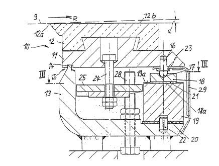
The stationary support device shown in Figures 1
to 3 has a cover ledge 10, which extends in the cross
machine direction, transversely to the direction of travel
(arrow R) of a wire drainage screen or wire 9 of a paper
making machine wire drainage section, or the like
installation. The cover ledge 10 comprises a moveable
3~ support ledge 11 below and a head ledge 12 which is arranged
9 ~ o
atop the support ledge 11, and the ledges are held together
by a dovetail connection. The head leclge is formed of a
hard, wear resistant material.
I'he head ledge 12 has a scraper-like front,
leading or upstream edge 12a which contacts the wire 9, and
preferably the bottom surface of the wire. A drainage
surface 12b meets and follows downstream from the front edge
12a and forms a small variable angle of inclination a with
respect to the path and direction of travel R of the wire 9.
In Figure 1, the entire dralnage surface 12b lies in a
single plane. One can, however, also deviate from this in
known manner. In Figures 1 and 4, the direction of travel R
of the wire 9 is shown as approximately horizontal. The
travel direction of the wire may alternatively be inclined
or be vertical. The orientation and position of
installation of the support device is adapted to the travel
direction of the wire.
The movable cover ledge 10 rests on a rigid
support 13. The support 13 has an L-shaped cross-section,
as seen in the lonqitudinal direction in Figure 1. The
upstanding front arm of the rigid support 13 extends in the
direction up toward the cover ledge 10. At its free upper
end, the support front arm has a narrow tongue 14 which
engages into a groove of slightly greater width beneath the
movable support ledge. The tongue 14 and the groove form a
tongue-in-groove joint 15, which is arranged in the region
of the front edge 12a of the head ledge 12. For a
horizontal direction of travel R of the wire, the joint 15
lies below the ledge front edge 12a. The tongue 14 and its
groove are shown with rectangular cross-sections. However,
other shapes, for instance, a semicircular cross section,
can be used.
In the region toward the rear of or downstream
along the support device, the movable support ledge 11 is
supported by a plurality of pins 16. Each pin 16 has a
~a~70
-- 8
spherically rounded bottom head 17, which rests via a slide
disk 18 on a respective wedge inclined surface of the wedge
ledge 19, and that ledge in turn rests on the rigid support
13. The wedge ledge 19 has a series of wedge-shaped
surfaces, each for engaging one slide disk. The wedge ledge
extends lengthwise, in the cross machine direction, over the
entire support device. It is displaceable in its
longitudinal direction, across the width of the support
ledge 11. The wedge ledge 19 is slidable between upper and
lower plate-shaped slide pieces 20 and 21 which have low
friction surfaces, i.e. plastic coatings or similar
intermediate layers, which reduce the frictional resistance
to movement of the wedge ledge. For guiding the movement of
the wedge ledge 19, a plurality of dowel pins 22 are
inserted in the support 13. The dowels 22 engage in a
longitudinal groove formed in the bottom side of the wedge
ledge. By means of the pins 16 and a respective spacer disk
23 for each pin 16, a cover plate 29 is fastened to the
movable support ledge 11 in order to protect the inside of
the wedge ledge 19 from being dirtied by pulp or drained off
water. The thickness of the various spacer disks 23, which
are distributed over the cross machine width of the support
device, may differ if necessary. Especially in case of
possible inaccuracies in manufacture, the angle of incline
of the cover ledge 10 can be established precisely,
uniformly over the cross machine width.
As seen in Figure 2, the wedge ledge 19 has a
plurality of inclined stop surfaces l9a, one of which is
shown at the right in Figure 2. Each stop surface is
correspondingly inclined along the cross machine width
direction. Each surface l9a is in contact with a stop
surface 18a of a respective one of the slide disks 18 for
that stop surface l9a. It is important that the slide disk
18 always contact the wedge ledge 19 flatly. This contact
9 ~ ~
angle is assured by the spherically curved bottom head 17 of
the pin 16 which engages into the slide ~isk.
In order that the movable cover ledge 10 might be
definitely pressed against both the joint 15 at the front
edge and the wedge ledge 19 toward the rear, a plurality of
tie rods 24 are distributed over the cross machine width of
the support device and are located generally in the central
region of the longitudinal cross-section of the movable
support ledge 11. A clamping element, in the form of a leaf
spring 25, acts on each tie rod (in the embodiment according
to Figures 1 to 3). In Figure 3, each leaf spring 25 has
the shape of a slender parallelogram which extends in the
cross machine direction. The central region of each leaf
spring 25 is connected via the upper tie rod 24 with the
moveable cover ledge 11. The opposite ends of adjacent leaf
springs 25 overlap each other laterally, and the overlapping
end regions are covered by a common rectangular shape spring
clamping plates 26. Each spring clamping plate 26 is
engaged by a common lower tie rod 27 which is screwed into
the rigid support 13. This tensions the leaf springs 25.
Upon the assembly of the support device, the cover
ledge 10 initially rests only on the joint 15 and on a few
au~iliary mounting screws 28 which are distributed over the
cross machine width of the support device because the wedge
ledge 19, the slide disks 18 and the cover plate 29 are
initially absent. These parts are only later installed
after the leaf springs 25 and the spring clamping plates 26
have been pretensioned by the tie rods 24 and 27. The
auxiliary mounting screws 28 are finally spaced a distance
away from the movable support ledge 11, as shown in Figures
1 and 2.
In the embodiment shown in Figure 4, instead of
the leaf springs serving for the clamping, an expandable
hose 30 is provided as the clamping element. The hose
extends over the entire cross machine length of the support
-- 10 --
device. Above the hose 30 is positioned a stationary force
transmission ledge 31. Below the hose is positioned a
movable force transmission ledge 32. Both force
transmission ledges extend in the cross machine direction
also substantially through the entire support device. The
hose 30 lies between the two force transmission ledges 31
and 32. Upon the hose 30 being pressurized, the hose
spreads the two force transmission ledges 31 and 32 apart in
the vertical direction.
One plurality of lower tie rods 33 connects the
stationary force transmission ledge to the rigid support
131. A second plurality of upper tie rods 34 connects the
moveable force transmission ledge 32 to the movable support
ledge 111. Because the movable force transmission ledge 32
is below the hose 30 and the stationary force transmission
ledge 31 is above the hose, cutouts for passage of the tie
rods 33 and 34 are provided in the force transmission
ledges. In order to obtain uniform spacing between the
mo~able force transmission ledge 32 and the movable support
ledge 111, spacing bushings 35 are provided for the ~ie rods
34. For attaching the cover plate 29, several cotter pins
36 are also providedr Other essential details of the
embodiment in Figure 4 correspond to those of the embodiment
of Figure 1 and are therefore provided with the same
reference numerals.
Although the present invention has been described
in relation to particular embodiments thereof, many other
variations and modifications and other uses will become
apparent to those skilled in the art. It is preferred,
therefore, that the present invention be limited not by the
specific disclosure herein, but only by the appended claims.