Note: Descriptions are shown in the official language in which they were submitted.
~ o~
DUAL SPRAY DIRECTOR USING AN "H" ANNULUS
Field of the Invention
This invention relates to electromagnetic
fuel in~ectors and in particular to an injector having
an orifice director plate downstream of the solenoid
10 actuated valve element and that has an upper face
channel system providing optimized distribution of fuel
to terminal fuel injection orifices regardless of the
amount of lift or position of the valve element from
the valve seat to inject cones of atomized spray with
15 quantities and direction optimized into separate intake
valves of an internal combustion engine.
Description of the Prior Art
Electromagnetic fuel injectors are employed
20 for internal combustion engines to effectively control
the discharge of precise quantities of fueI per unit of
time for optimized engine performance. Such fuel
injectors are normally calibrated so as to inject this
predetermined quantity of fuel prior to their
25 installation in the fuel system of a particular engine.
An example of one such electromagnetic fuel
injector is disclosed in U.S. Patent No. 4,699,323
entitled "Dual Spray Cone Electromagnetic Fuel
Injector" dated October 13, lga7 and issued to James E~.
30 Rush et al. and assigned to the assignee of this
invention . A di rector plate downstream of a solenoid
control valve has two sets of three orifice passages or
holes arranged on opposite sides of a vertical plane
~45~4
extending through the reciprocating axis of the valve
so that the streams of fuel discharged therefrom
partially impinge on each other whereby the two sets of
orifice passages are operative to produce two diverging
5 atomized cone fuel spray patterns for supplying fuel to
two intake valve6 of a multi-valve per cylinder
internal combustion.
While the six hole multiple plate dual cone
director described in this prior patent has performed
10 with good results, it is difficult and costly to
manufacture and the spray patterns may not meet higher
standards for optimized fuel delivery with effective
part cost reduction. More particularly, with the prior
art construction, the spray patterns were sensitive to
15 the position and the amount of core ball lift so for
example there was excessive skew (angular misdirection)
of the fuel spray cones when the injector was used on
engine applications requiring low or short lift. To
make such an injector effective, costly and tedious
20 part matching would be required for an even more closer
fit of the parts so that the valve element still
readily shifts and shifts with high precision to
closely controlled positions along its longitudinal
axis for an even flow of fuel onto the director plate
25 for improving the targeting of the fuel spray cones.
With the present invention, the above difficulties are
obviated with a new and improved fuel injector which
can be utilized in a wide range of engine applications
with minimized skew and improved efficiency.
SUMMARY OF T~E INV~NTION
~ ccordingly, it is a feature ob~ect and
advantage of the present invention to provide a new and
2~
lmproved electromagnetic ~uel injector for use in a
wide range of engine applications having an orifice
director plate incorporated therein, downstream of the
solenoid control valve of the injector and positioned
5 at right angle6 to the reciprocating axis of the valve.
The orifice director plate in the preferred embodiment
is of nickel plate and has ~our orifices interconnected
by a flow distribution system formed in the upper
surface of the director plate. This system is a
10 balanced fuel flow channel system that has passages
which lead into each injector orifice so that dual and
quantitatively equalized cones of fuel spray will be
directed with minimized skew and maximized precision to
the intake valve o~ an internal combustion engine
15 regardless of the position of the core ball as it lifts
from the valve seat located at the lower nozzle of the
inj ector .
Another feature object and advantage of this
invention is to provide a new and improved director
20 plate for a fuel injector which has sets of injection
orifices on opposite sides of a plane, extending
through the axi~, with the injection orifices arranged
so that the streams of fuel partially impinge on each
other, whereby two sets of orifices are operative in
25 providing two diverging atomi2ed cone fuel spray
patterns for supplying fuel to separate intake valves
for a multiple valve cylinder of an internal combustion
engine .
Another feature object and advantage of this
30 invention is to provide a new and improved director
plate for a fuel injector which has sets of injection
orifices on opposite sides of a plane, extending
through the axis, with the injection orifices arranged
~4~05~
so that the streams of fuel partially impinge on each
other, whereby two sets of orifices are operative in
providing two diverging atomized cone fuel spray
p~tterns for supplying fuel to separate intake valves
5 for a multiple valve cylinder of an internal combustion
eng i ne .
Another feature object and advantage of this
invention is to provide a new and improved
electromagnetic fuel injector with matched set of
10 injector orifices in a director plate inclined with
respect to the shift axis of t~e valve and having a
fuel distributing system interconnecting the injection
orifices so that each injection orifice receives
substantially the same quantity of pressure fuel
15 producing matched multiple streams of fuel; adjacent
streams of which interact to provide an atomized cone
of fuel which accurately impinges upon a target such as
the intake valve of an internal combustion engine.
Another feature object and advantage of this
20 invention i5 to provide a new and improved
electromagnetic fuel injector, having a valve element
displaced at any selected amount of lift from a fuel
feed orifice by movement of its core ball from its
associated valve seat so that the director plate
25 optimally distributes fuel flowing through the valve
body by a flow directional system: the system
terminating in injection orifices spaced such that two
adjacent jets of fuel laving adjacent orifices
partially overlap, resulting in a directed cone of fuel
30 that accurately impacts on a target su~h as the intake
valve of a cylinder of an internal combustion engine.
Another feature object and advantage of this
invention is to provide a new and improved director
2~ 54
plate for a multiple spray cone electromagnetic fuel
injector that ha6 a generally H shaped fuel
distribution system channeled within the inner face
thereof which terminates at adjacent injection orlfices
5 at the end of each leg of the H pattern so that fuel
fed thereto will be optimally distributed, regardless
of the position of the controlling valve element from
its valve seat, so that dual spray cones will be
injected into the intake port and onto the intake
10 valves of a combustion cylinder of an internal
combustion engine without excessive wetting of the side
walls of a septum dividing the intake valves from one
anothe r .
These and other feature objects and
15 ~dvantages of this invention will be more apparent from
the following Detailed Description and Drawing.
sRIEF DESCRIPTION OF THE DRAWINGS
Figure l is a schematic illustration of the
20 induction system for supplying fuel to the intake
valves of a cylinder of an internal combustion engine.
Figure 2 is a longitudinal cross sectional
view of an electromagnetic fuel injector incorporating
~ fuel director plate according to this invention for
25 directing separate cones of spray fuel according to the
present invention.
Figure 3 is an enlarged view of the encircled
lower end portion of the injector of Figure 2 but with
components moved so that the director plate directs
30 cones of fuel to a target area.
Figure 4 is a top plan view of the director
pl~te taken generally along sight lines 4-4
diagrammatically illustrating the fuel flow
2~0~
distribution pattern provided by the director plate of
this invention.
Figure 5 is a sectional view taken along
sight lines 5-5 of Figure 4.
DESCRIPTION OF THE PREFERRED EM30DIMENT
Turning now in greater detail to the drawing,
there is diagrammatically shown in Figure 1, ~uel
injector 10 operatively mounted in an intake manifold
10 12 of an internal combustion engine 14. This injector
10 i6 operative to inject a pair of discrete spray
cones of fuel 16 and 18 through a special fuel director
plate 20 operatively mounted within the lower end of
the injector. These spray cones are accurately
15 targeted to project, without wall wetting, through
discrete passages of intake port 22 partitioned by a
septum 23 onto separate intake valves 24 and 26 of a
power cylinder 32 of the internal combustion engine.
The spray cones 16 and 18 mixed with intake air,
20 exemplified by flow arrows 34, flowing through the
opened intake valves provide a fuel air charge for the
engine cylinder 30. This charge is ignited by a spark
plug 36 on predetermined position of the piston in
compression stroke. On exhaust stroke, the exhaust
25 valves 38 and 40 open to discharge the exhaust gases
from the cylinder 32 to an exhaust port 42 and then to
~n exhaust manifold not shown leading from the engine.
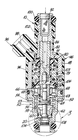
A preferred form of the fuel injector and the
special injector plate providing the important benefits
30 of this invention is shown in Figures 2 through 5. The
injector 10 with the exception of the director plate
and its operation generally corresponds to the dual
spray cone electromagnetic fuel injector of U.S. Patent
.
2~5~4
No. 4,699,323 dated October 13, 1987 assigned to the
Assignee of this invention.
The injector 10 has an upper solenoid
5 assembly 46 with a generally cylindrical and stepped
diameter metallic shell 48 having a skirt portion 50 at
the lower end thereof that receives the upper end of a
nozzle assembly 52, which has a cylindrical stepped
diameter main casing 53. The annular end 54 of the
10 skirt portion 50 of the shell 48 is crimped inwardly to
grip the enlarged head portion of the nozzle casing to
fasten the noz21e assembly 52 to the lower end of the
injector shell to rigidly secure these parts together.
Operatively mounted for linear movement
15 within the nozzle casing 53, is a reciprocally movable
and elongated valve element 56 having at its lower end
a semi spherical core ball 58, which is adapted to be
moved from a seated and fuel sealing engagement with an
annular valve seat 60 defining a flow orifice passage
20 51 of a cylindrical valve body 62 mounted within the
nozzle casing that is yieldably held in position by an
outer helical spring 63.
The valve element 56 is controlled in its
movement by the electromagnetic force of a periodically
25 energizable coil of a solenoid assembly operatively
mounted in the injector shell and the opposing spring
force of a helical return spring 64. The lower end
coil of spring 64 is seated on a centralized large
diameter collar formed on the valve element
30 intermediate the ends thereof while upper end coil of
spring 64 is seated on annular spacer disc 66 having
axial fuel feed passages 6~ extending therethrough.
2~4~4
.
The cylindrical upper end o~ the valve
element 56 is press fitted into a cylindrical armature
70 which strokes with radi~l clearance in a centralized
annular opening 72 in the spacer disc 66 and in the
5 guide washer 74 fixed atop of the spacer disc. Due to
the normal limit 6tack dimensional variations and
particular those in the spacer disc, guide washer and
armature, variations occur in the centering or
~lignment between core ball with respect to it~ valve
10 seat and the surrounding wall of the valve body.
Accordingly on valve lift, fuel flow around the core
ball varies with the amount of vertical lift from its
valve seat and its radial displacement from the center
line of the injector. Such variation may result in an
15 uneven distribution of fuel flowing around the core
ball, as illustrated in Figure 3, which shows the core
ball 58 lifted a predetermined vertical distance from
valve seat 60 by action of the solenoid assembly. In
this position the axis A' of the core ball may be
20 radially or otherwise offset a sight amount from the
vertical axis A of the valve seat 60 of the injector
10. Under such conditions, there is more fluid flow
clearance on one side of the core ball than the other
~s illustrated by clearances C and C'. Accordingly,
25 flow capacity on one side of the core ball, clearance
C, is larger than the other side, clearance C~ and a
larger quantity of fuel flows to the flow orifice
passage as through clearance side C compared to the
opposing side o the core ball. With unequal flow of
30 fuel around the core ball onto the director plate as
indicated by flow arrows F, F', difficulties have been
experienced in optimizing injection of fuel onto the
intake valves particularly in installations in which
2~0~
there is maximized core ball lift as determined by a
stop mechanism described below. However, the valve
director dific of this invention is substantially
independent of the position of the core ball and will
distribute fuel impinging thereon to the matched pairs
of injection orifices 116, 118 and 120, 122 in the fuel
director plate 20 as best shown in Figure 4.
Valve lift occurs on energization of a coil
79, the terms of which are wound on a bobbin 80 made of
insulated plastics material which encompasses an
elongated solenoid stator 82 that forms the core of the
solenoid assembly. A stop 85 pressed into the lower
end of stator 82 contacts the end of plug 87 pressed in
armature 70 to limit the amount of vertical lift of the
valve. The stator has a centralized fuel flow passage
86 leading from its upper end to radial intermediate
flow passage 88 and 90. Low pressure fuel is fed to
the centralized stator passage 86 through a fuel filter
unit 92 operatively mounted in an inlet chamber
provided in the reduced diameter upper end of the
metallic shell 48.
As shown, the shell is encased within a tough
insulating plastics material 94, which is formed with
an elongated side socket 96 having a pai r of electrical
leads, one of which is shown at 98 that operatively
connects the coil 79 to a control source of electrical
power which affects the electromagnetic operation of a
fuel injector by pulses fed thereto from a controller
not shown.
The upper end of the fuel injector 10 is
fitted with an O-ring lO0 and has as annular connector
groove 102 for leak free attachment to a fuel line in a
conventional manner.
20~5~
When the core ball 58 is lifted from its seat
for fuel injection, low pressure fuel can flow through
the fuel filter g2 and the stator via the central and
radial passages therein. From the radial passages, the
5 fuel flows through the annular passage 103 around the
lower end of the stator and then into an annular cavity
104 at the lower end of the solenoid bobbin 80. The
fuel then flows through the axial passages 68 in the
spacer disc and around the core ball in varying
10 patterns through clearances C and C' as described above
and through the central opening 51 defined by the
annular valve seat 60 in the valve body 62 and onto the
flow director plate 20 of this invention.
The flow director plate 20 is supported in
15 fixed position between the lower end of the valve body
62 and a cylindrical retainer 106 which is adjustably
threaded into an inner diameter of nozzle casing 53 by
means of conventional tooling having a hex head which
fits into the opening 108 formed within this retainer.
In Figure 3, the core ball is lifted from the
valve seat a predetermined distance from its valve seat
as determined by stop 85, shown in Figure 1. AS
indicated above, in high quantity production limit
stack variations occur so that the core ball of one
injector might be lifted to a slightly different height
than the core ball of another injector, and could be
offset from the center line by a distance slightly more
or less than that of a second unit. Regardless of
amount of axial lift or amount of radial offset within
tolerances, the present invention provides
substantially equalized dual spray cones of fuel 16, 18
which are directed through discrete passages of intake
port 22 on either side of the septum and are directed
2~50~
11
with precision onto the two intake valves.
Furthermore, the injector of this invention can be used
in a wide range of engines since targeting of the fuel
~pray is not sensitive to core ball location. In
5 particular, this invention can be used with engines
requiring low lift as well as those requiring high lift
of the core ball.
One preferred embodiment of the fuel director
plate 20 is shown in Figure 4 in which a channeled H
10 6haped fuel flow distribution system 110 is formed in
the upper face of the director plate. As illustrated,
the side legs 112 and 114 of the system are opposing
arcs of a circle and the terminal ends of these legs
have fuel injection orifices 116, 118 and 120, 122
15 formed therein such as by electron discharge machining
at set predetermined angles with respect to the plane
of the director plate. The two arcuate legs 112 and
114 are hydraulically interconnected by a wide central
diametrical channel 124. with this distribution
20 pattern, fuel flowing onto the director plate under low
pressure will follow paths of least resistance and be
distributed substantially equally in guantity to the
four injection orifices 116, 118 and 120, 122 as
diagrammatically illustrated by flow distribution
25 arrows D, D~.
In this system closely adjacent orifices are
engineered to cooperate with one another to provide the
desired cones of fuel spray 16 and 18. Accordingly,
equalized streams of fuel 126 and 128 will partially
30 intersect one another as diagrammatically illustrated
in Figure 3 to limit ~pray cone diameter and thereby
11
20450~
12
prevent wall wetting and to provide improved
directional control for impingement onto intake valve
26 of fuel spray cone 16.
Fuel spray cone 18 is similarly provided by
the partial intersection of streams of fuel 130, 132
through orifices 120 and 122 to impinge upon intake
valve 24 with accurate targeting and without
sensitivity to core ball location.
The H pattern distribution system eliminates
or substantially reduces skew angle so that there is
substantially no wetting of the walls of the intake and
the spray will be more accurately targeted onto the
intake valves for improved engine performance, and
particularly when there is requirement for high torque
response with appropriate quantities of fuel for
~cceleration purposes. This invention, as indicated,
eliminates rich fuel during deceleration because there
will be minimized fuel on the port wall for all
applications .
It will be apparent to those skilled in the
art, that the electromagnetic fuel injector having an
orifice director plate in accordance with the present
invention could also be used to supply fuel to adjacent
cylinders of an engine of the type having a single
intake valve and single eYhaust valve associate with
each cylinder. Alternatively, the electromagnetic fuel
injector could be used to supply fuel to the two bores
of an otherwise conventional two bore throttle body
injection system.
Accordingly, the application is intended to
cover the illustrated and other modifications or
changes as may come within the scope of the following
claims .
12