Note: Descriptions are shown in the official language in which they were submitted.
- 1 2 G~513!~
AUTOMATIC SWlNG FISHWAY APPARATUS
The present invention relates to an automatic swing
fishway apparatus to allow fish to swim upstream and which
is installed in dams or weirs and is able to accommodate
fluctuations in upstream water levels.
As indicated in Fig. 10 of the drawings, this type of
apparatus conventionally involves a reservoir 2, formed by
dam 1, being connected to a downstream stationary fishway 4
via guiding waterway 3, with swing fishway apparatus 5
provided at an intermediate location in the waterway. Water
pressure chamber 6 is provided in said waterway, and a
fishway device body 7 is housed within said hydraulic
chamber and pivotably supported at its downstream end by a
shaft 7a. The upstream end of body 7 is raised or lowered
by a winch 8. A plurality of dividing walls 9 are provided
in the upper portion of body 7. Fishway device body 7 is
tilted corresponding to the water level of reservoir 2 with
shaft 7a at the downstream end of body 7 serving as the
fulcrum. In the case of this device, as the operator must
check the water level and then operate winch 8 to lift
fishway body 7 and tilt it to match the upstream water
level, the apparatus demonstrates poor ease of use as it is
slow in following fluctuations in the water level.
Thus, Japanese Utility Model Publication No. 59-17941
discloses an invention in which the fishway device body
inclines to match the upstream water level automatically
without the use of winch 8. As is indicated in Figs. 11, 12
and 13, frame 11, which is provided with small openings left
between side walls 10 on both sides of the waterway, is
supported by a shaft on the downstream end, allowing the
device body to swing freely. A connecting tube 12 opens
into the bottom of frame 11 and also into the upstream
water. Floats 13 in the form of plates are provided
vertically at constant intervals on frame 11. Regulatory
chambers 14 are provided within floats 13 and water is fed
to these from water feed ports 15 to regulate the buoyancy
. ~,
- 2 - 2045139
of floats 13. Therefore, frame 11 is supported by the
buoyancy of floats 13 and the water pressure which acts on
the bottom surface of frame 11.
As said frame 11 is not simply floating in the water by
S floats 13, the angle of inclination of frame 11 is set by
regulating the buoyancy by introducing water into regulatory
chambers 14 from water feed ports 15 at the time of
installation.
However, since the buoyancy fluctuates according to the
angle of inclination, when the water level in the reservoir
rises, frame 11 rises too high resulting in the amount of
water which overflows floats 13 to decrease. Since the
depth of the overflow water is too shallow, it is not
suitable as a fishway. If the condition where the water
level is high is accommodated, the inclination of frame 11
becomes too small when the water level in the reservoir
lowers resulting in the water flow becoming excessive.
Thus, a fishway is desired which achieves a suitable
overflow water depth regardless of the height of the
upstream water level.
The purpose of the present invention is to provide an
automatic swinging fishway device that is able to accurately
follow fluctuations in the upstream water level.
Thus, in accordance with the present invention, an
automatic swing fishway apparatus comprising:
a hydraulic chamber provided in a bottom of a waterway
which bypasses a dam; and
a fishway device body comprising:
a fishway portion provided above the hydraulic chamber
and having a floor plate and a plurality of dividing walls
provided vertically on the floor plate:
a sealed buoyant portion provided beneath the floor
plate;
the fishway device body having an upstream end and a
downstream end and provided with a main shaft arranged at
~'
- 3 ~ 20 ~5139
the downstream end of the fishway device body so that the
fishway device body can rotate freely;
an overflow weir at the upstream end of the fishway
device body; and
means for connecting the hydraulic chamber to an
upstream end of the fishway device body through the overflow
weir; and
an outflow port for connecting the hydraulic chamber to
a downstream waterway, wherein the inclination of the
fishway device body is changed in accordance with a water
level of the dam by equalizing an amount of water flowing
over the overflow weir into the hydraulic chamber to an
amount of water flowing from the hydraulic chamber via the
outflow port.
As a result of having the construction described above,
the fishway device body is raised by the buoyancy of the
sealed portion following the flowing in of water that has
overflowed the overflow weir into the hydraulic chamber. If
the water level in the reservoir rises, the amount of water
flowing into the hydraulic chamber becomes greater than that
flowing out. The fishway device body then rotates about the
downstream end so that the upstream end rises and the angle
of inclination becomes larger. Since the overflow weir also
rises at this time, the amount of overflow is decreased
until the fishway device body stops at a position at which
it is balanced. The depth of the water overflowing The
dividing walls is thus maintained. In addition, if the
water level in the reservoir lowers, the amount of overflow
will decrease and the amount of water flowing in will become
less than that flowing out. As a result, the water in the
hydraulic chamber will decrease and the fishway device body
will be lowered. Thus, the amount of overflow water will
increase until the fishway device body stops at a position
at which it is balanced.
The invention will now be described further by way of
example only and with reference to the accompanying
drawings, wherein:
~.i
., ~
- 4 - 2 0 451~ g
Fig. 1 is a cross-sectional side view of one embodiment
of the automatic swing fishway apparatus of the present
invention;
Fig. 2 is an overhead view of Fig. l;
Fig. 3 is a cross-sectional view of the upstream side
of one embodiment of the automatic swing fishway apparatus:
Fig. 4 is a cross-sectional side view of the key
components of one embodiment of the automatic swing fishway
apparatus;
Fig. ~ is a transverse cross-sectional view of the
downstream side of one embodiment of the automatic swing
fishway apparatus;
Fig. 6 is a transverse cross-sectional view of the
upstream side of one embodiment of the automatic swing
fishway apparatus;
Fig. 7 is a cross-sectional view of the downstream end
of one embodiment of the automatic swing fishway apparatus;
Fig. 8 is a cross-sectional side view of a dam using
one emho~;ment of the automatic swing fishway apparatus;
Fig. 9 is an overhead view of Fig. 8;
Fig. 10 is a cross-sectional side view of the swing
fishway apparatus of the prior art;
Fig. 11 is an overhead view of another swing fishway
apparatus of the prior art;
Fig. 12 is a cross-sectional side view of Fig. 11; and
Fig. 13 is a transverse cross-sectional view of Fig. 11.
Referring now to the drawings, as is indicated in Figs.
8 and 9, dam 17 is constructed in river 16. Guiding
waterway 19 which connects with reservoir 18 is formed in
dam 17, and is connected to stationary fishway 21 which
merges with the downstream flow of the river via swing
fishway apparatus 20. Guiding waterway 19 is of sufficient
depth to allow the water level to remain constant from the
set highest water level to the lowest water level with
respect to reservoir 18. An emergency dam door 22 is
provided at the entrance to guiding waterway 19, which is
normally raised up to allow water to flow into the waterway.
- 5 - 20~5 139
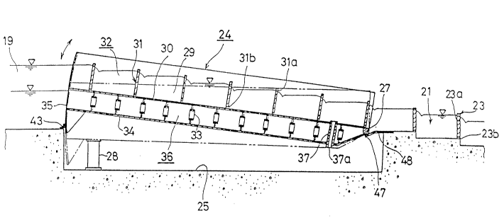
As is indicated in Figs. 1, 2 and 5, stationary fishway
21 is divided up by a plurality of dividing walls 23
provided at fixed intervals along an inclined surface. The
bottom of said stationary fishway is typically in the form
of steps. A portion of the top of each dividing wall 23 is
cut away resulting in the formation of notches 23a. Water
is allowed to flow down through these portions. In
addition, small-diameter mud discharge ports 23b are opened
in the bottom portions of dividing walls 23.
Fishway device body 24 of swing fishway apparatus 20 is
contained within hydraulic chamber 25 which is opened in the
bottom portion and which connects guiding waterway 19 and
stationary fishway 21. The lower end of fishway device body
24 is anchored on main shaft 27 which engages with bearings
26 embedded in the upper portions of the side walls near the
downstream end of hydraulic chamber 25, and is allowed to
rotate freely so as to change the weir height at the upper
end. In addition, the width of the upstream end of
hydraulic chamber 25 is enlarged as seen in Fig. 2 and frame
28 is installed on the bottom of chamber 25, which maintains
the orientation of fishway device body 24 at its lowest
point.
Fishway portion 32 is defined by floor plate 30, on
which side plates 29 are mounted on both sides. Fishway
portion 32 is also divided by a plurality of dividing walls
31 in which are formed notches 31a by cutting out a portion
of the top end of each said dividing wall 31. Furthermore,
small-diameter liquid discharge ports 31b are opened in the
bottom portions of dividing walls 31. In addition, bottom
plate 34 is attached beneath floor plate 30, on which is
arranged porous support members 33, and the downstream end
of bottom plate 34 is bent upward to close off the space
between bottom plate 34 and floor plate 30, while the
upstream end of the space between bottom plate 34 and floor
plate 30 is closed off as a result of the presence of
arcuate end plate 35 which has its centre of curvature on
- :,~ , .
- 6 - 2 04 5139
main shaft 27. Thus, a sealed portion 36 is formed beneath
the floor plate. In addition, outflow tube 37, which
connects the lowest flow portion divided by dividing walls
31 with hydraulic chamber 25, is mounted to pass through
sealed portion 36 and outflow port 37a, which opens into
hydraulic chamber 25, is able to follow decreases in the
water level of reservoir 18.
As is indicated in Figs. 2, 3 and 6, an enlarged
portion 30a is formed on floor plate 30 protruding on both
sides of its upstream end. Side walls 38 are mounted on
both sides of said enlarged portion, and overflow weir 39 is
provided behind said enlarged portion, with retarding basins
40 defined on the left and right by end plate 35, overflow
weir 39 and side walls 38. Inflow ports 41 are provided in
end plate 35 slightly above the floor surface 30 of fishway
portion 32, which communicate with retarding basins 40.
Ports 41 are suitably sized to prevent infiltration of waves
and debris, whilst allowing the passage of specified amounts
of water. The end plate 35 protrudes to the sides slightly
more than the front of retarding basins 40. In addition,
water feed tanks 42 are formed downstream from overflow weir
39 by the side walls of hydraulic chamber 25, and are also
connected with hydraulic chamber 25. The bottom of end
plate 35 is extended so that it remains in contact with the
side walls of the upstream side of hydraulic chamber 25 even
when fishway device body 24 is at its maximum inclination.
In addition, dividing wall 31s, which is the farthest
upstream, is in the same plane as overflow weir 39. The
upper end of overflow weir 39 is several centimeters lower
than dividing wall 31s, and the diameter of outflow port 37a
is sufficiently smaller than the length of overflow dam 39.
The following provides an explanation of the stoppage
of water moving in sequence from the upstream side.
Front rubber water stopper 43 on the bottom of the
downstream end of guiding waterway 19 is provided so as to
make contact with the upstream side surface of end plate 35
~-A~
_ 7 _ 2 01~13 9
to stop the flow of water on the upstream side. In
addition, as is indicated in Fig. 4, an opening of suitable
size is provided between fishway device body 24 and
hydraulic chamber 25 so as to allow the discharge of leakage
water. Bottom plate 34 protrudes to the side farther than
side plates 29 and is anchored to its bottom surface and
upstream end. Side rubber water stopper 45 is mounted on
the upstream surface of vertical rubber attachment piece 44
which rises vertically at a right angle from that point.
The end of side rubber water stopper 45 makes contact with
the side wall surface of hydraulic chamber 25 which is given
a resin coating. Thus, it is obvious that the position of
vertical rubber attachment piece 44 is slightly downstream
of the downstream end of feed water tank 42. The downstream
end of side rubber water stopper 45 extends to the bottom of
main shaft 27. With respect to the stopping of the flow of
water on the downstream end, as is indicated in Fig. 5, back
rubber attachment piece 46 is mounted the width of the
waterway on the surface of floor plate 34 near main shaft
27, with both ends of piece 46 forming a slight gap with the
rear surface of the respective side rubber water stopper
45. Back rubber water stopper 47 is mounted in the shape of
a plate on the upstream surface of back rubber attachment
piece 46, and both ends are in contact with the rear surface
of the respective side rubber water stopper 45. In
addition, an opening is provided between main shaft 27 and
the downstream end of hydraulic chamber 25 so that the
operator can enter said hydraulic chamber 25. Back closing
member 48, which is mounted on the bottom of stationary
fishway 21 and extends to the upstream side, makes contact
with back rubber water stopper 47.
In the case where the water level of reservoir 18 is at
its lowest level, the difference between the minimum water
level of the reservoir 18 and the water level of the
compartment which is furthest downstream is sufficiently
large that if the potential inside hydraulic chamber 25
204~139
-- 8 --
becomes equal to the minimum water level of the main
current, the fishway device body 24 will rise. If it
becomes equal to the water level of the compartment farthest
downstream into which outflow tube 37 opens, fishway device
body 24 will lower.
A screen 49 is mounted near the upper end of water feed
tank 42 so that it can be attached and removed as desired.
A pair of side rollers 50 are mounted on the bottom of
floor plate 34 near the upstream end.
The planar surface area of water feed tank 42 should be
as small as possible and the lower end of each retarding
basin 40 should be sufficiently low that it is not exposed
to air.
Furthermore, although the shape of fishway device body
24 is rectangular in this embodiment, as its operation will
no longer be smooth due to the amount of each movement
becoming large when the free water surface is formed beneath
it as it rises, as is explained in the following section
discussing the operation of the present invention, it may
inhibit the formation of a free water surface by being in
the basic shape of a fan.
The following provides an explanation of the operation
of the present invention. The explanation will start with
the state in which the fishway device body 24 is stationary
being supported by a frame 28. When dam 17 is completed,
accumulation of water begins and the water level rises in
reservoir 18, and the water level in retarding basins 40,
connected to this via guiding waterway 19 and inflow ports
41, will also rise. Then, before the depth of the overflow
water of notches 31a formed in dividing walls 31 becomes
eYcessive, overflow begins over overflow weir 39 and water
flows into hydraulic chamber 25 through water feed tank 42.
Together with water filling hydraulic chamber 25, outflow of
water also begins from outflow port 37a. At that time,
since the length of overflow weir 39 is sufficiently large
by comparison with outflow port 37a, the water level in
20~5139
water feed tank 42 rises and the water pressure which acts
on the bottom of fishway device body 24 increases. The
upstream end of fishway device body 24 rises, pivoting on
main shaft 27 on the downstream end, causing fishway device
body to become inclined. When fishway device body rises,
the depth of the overflow water flowing over overflow weir
39 naturally decreases, and the angle of inclination of
fishway device body 24 is maintained as a result of reaching
a state of balance with this water pressure. If the
upstream water level rises and the depth of the overflow
water increases even slightly, although the fishway device
body 24 rises due to this water pressure, since overflow
weir 39 also rises, the depth of the overflow water flowing
over overflow weir 39 decreases. As a result, the amount of
water flowing into water feed tank 42 that had once been
increasing now decreases, and its water level returns to its
original level. Since the water pressure acting on the
bottom of fishway device body 24 becomes constant, fishway
device body 24 becomes motionless and the depth of the
overflow water flowing over notches 31a is maintained at a
proper level. The case in which the upstream water level
becomes lower will be described later.
Next, an explanation is provided regarding the
magnitude of each movement of swing fishway apparatus 20.
In the case of the devices of the prior art, although the
resistance when the fishway device body 24 begins to move is
in the form of static friction resistance and is
comparatively large, once it begins to move, this resistance
becomes kinetic friction resistance and decreases
dramatically. Thus, the movement of fishway device body 24
tends to be too large.
In the case of the swinging fishway device 20 of the
present invention, since the surface area of water feed tank
42 is made to be sufficiently small in comparison with the
planar surface area of hydraulic chamber 25, when fishway
device body 24 rises even only slightly, the water level in
;..
~ ,
- lO 2045139
water feed tank 42 decreases considerably resulting in
dramatic decrease in operating force. Therefore, there is
no possibility of fishway device body 24 demonstrating a
large movement all at once.
S However, if the rise in the water level of reservoir 18
continues, as the amount of water flowing in from overflow
weir 39 gradually increases, fishway device body 24
continues to rise gradually.
The following provides an explanation of the action of
the present invention when fishway device body 24 lowers.
When the water level of reservoir 18 lowers and the depth of
the overflow water flowing over overflow weir 39 decreases
slightly, the reduction in the amount of water flowing into
water feed tank 42 becomes large. Therefore, since the
amount of water being discharged from outflow port 37a
cannot be completely replenished, the water level in water
feed tank 42 decreases and the water pressure acting on the
bottom of fishway device body 24 also decreases causing it
to lower. In this case also, although the fact that each
movement is extremely small need not be explained again, as
the size of outflow port 37a is determined in consideration
of the rate of decrease of the water level of reservoir 18,
there is virtually no occurrence of a sudden decrease in the
amount of flow within the fishway portion 32 since it cannot
completely follow the decrease in the water level of
reservoir 18.
Next, an explanation is provided regarding the problem
of leakage of water from the end of side rubber water
stopper 45. Since the gap between side plate 29 of fishway
device body 24 and the side wall of hydraulic chamber 25 is
of a suitable size, water that has leaked is able to merge
with the upstream end of stationary fishway 21 through that
gap.
As has been described above, the present invention is
able to automatically rotate the fishway device body while
following the water level of the reservoir through the
11- 20~5139
utilization of the natural force of water flow and without
the use of mech~nical force, while also being able to
maintain the depth of the overflow water, and in turn the
flow volume, at a nearly constant level regardless of the
water level of the reservoir. Moreover, since the present
invention involves only the provision of an overflow weir
and outflow port, connecting them to the inside of a
hydraulic chamber, and sealing the hydraulic chamber with
the fishway device body, management costs as well as
construction costs can be reduced.