Language selection

Search

Patent 2045243 Summary

Third-party information liability

Some of the information on this Web page has been provided by external sources. The Government of Canada is not responsible for the accuracy, reliability or currency of the information supplied by external sources. Users wishing to rely upon this information should consult directly with the source of the information. Content provided by external sources is not subject to official languages, privacy and accessibility requirements.

Claims and Abstract availability

Any discrepancies in the text and image of the Claims and Abstract are due to differing posting times. Text of the Claims and Abstract are posted:

  • At the time the application is open to public inspection;
  • At the time of issue of the patent (grant).
(12) Patent: (11) CA 2045243
(54) English Title: LADDER FOR FRAGILE PARTICULATE COMMODITIES
(54) French Title: ECHELLE POUR PARTICULES FRAGILES
Status: Expired and beyond the Period of Reversal
Bibliographic Data
(51) International Patent Classification (IPC):
  • B65G 11/08 (2006.01)
(72) Inventors :
  • DUNNIGAN, THEODORE J. (United States of America)
(73) Owners :
  • THEODORE J. DUNNIGAN
(71) Applicants :
(74) Agent: SMART & BIGGAR LP
(74) Associate agent:
(45) Issued: 1996-04-23
(22) Filed Date: 1991-06-21
(41) Open to Public Inspection: 1992-05-29
Examination requested: 1992-04-24
Availability of licence: N/A
Dedicated to the Public: N/A
(25) Language of filing: English

Patent Cooperation Treaty (PCT): No

(30) Application Priority Data:
Application No. Country/Territory Date
07/619,083 (United States of America) 1990-11-28

Abstracts

English Abstract


An apparatus for lowering particulate commodities includes a
vertically disposed ladder extending from the upper end of the
storage facility to the lower end of the storage facility. The
ladder is formed of flexible planar sheets bent upon themselves
to define substantially U-shaped chute member formed into a
zigzag pattern such that the particulate commodities flow
downward through the chute members passing from one chute member
to the next chute member. The chute members are connected such
that an opening is formed at the upper end of each chute member
so that the commodities may exit the ladder once the level of
the commodity within the storage facility has reached the upper
end of a particular chute member.


Claims

Note: Claims are shown in the official language in which they were submitted.

The embodiments of the invention in which an exclusive
property or privilege is claimed are defined as follows:
1.
An apparatus for lowering fragile, particulate commodities into a commodity
storage facility, comprising:
a vertically disposed ladder means having upper and lower ends;
means for supporting said ladder means within the storage facility so that the lower end
thereof is positioned adjacent the lower end of the storage facility,
the upper end of said ladder means being in communication with a source of
commodities;
said ladder means comprising a plurality of resilient, flexible planar sheets, each of said
sheets being bent upon itself to define a substantially U-shaped chute member
having upper and lower ends;
the lower end of each chute member, except the lowermost chute member, being
secured to the upper end of the chute member positioned therebelow, adjacent
chute members being oppositely disposed with respect to one another to define
a zigzag pattern, whereby the particulate commodities will flow downward
through said chute members passing from one chute member to the next chute
member positioned therebelow;
adjacent chute members defining an opening at the connection therebetween whereby
the particulate commodities may exit the ladder therethrough once the level of
commodity within the storage facility has reached that level.
- 6 -

2.
The apparatus of claim 1, further comprising means for
selectively, adjustably securing the lower ends of the chute
members to the upper ends of the chute members positioned
therebelow, so as to selectively adjust the slope of each chute
member in the zigzag pattern, whereby the speed at which a
commodity passes through said ladder means may be adjusted.
3.
The apparatus of claim 1, wherein said means for supporting
said ladder means within the storage facility includes a
flexible chain means connected to the upper ends of parallel
chute members defining the "zig" portion of the zigzag pattern.
4.
The apparatus of claim 3, wherein said means for supporting
said ladder means within the storage facility further includes
chain means connected to the upper ends of the parallel chutes
forming the "zag" portion of the zigzag pattern.
7 -

Description

Note: Descriptions are shown in the official language in which they were submitted.


Technical Field 20~S243
The present invention relates generally to a ladder for
lowering fragile, particulate commodities into a storage
facility, and more particularly to a ladder which may remain in
5place within the storage facility during loading of the
facility.
~ackqround of the Invention
Zigzag shaped chutes have long been utilized to lower fruits
and vegetables from an upper level to a lower level, to avoid
10damaging the commodities. The falling speed of the commodities
is reduced by frequently changing the direction that the
commodity is falling within the chute.
One problem with prior art zigzag chutes is in the need to
remove the chute as the storage facility is filled with the
15commodity, to prevent damage to the chute under the pressure of
the commodity within the storage facility. To avoid damage to
the chute, prior art chutes are designed to be progressively
raised with the level of the commodity in the facility.
However, this capability complicates the structure of the chute,
20requiring additional time and labor in construction, and adding
to the overall weight of the finished chute.
It is therefore a general object of the present invention to
provide an improved ladder for lowering fragile commodities
within a storage facility.
25Another object is to provide a ladder which is resiliently
collapsible so that it may remain in a storage facility after
filling of the facility, and yet be reusable.
A further object of the present invention is to provide a
ladder whicll is light weight, simple in operation and economical
30to manufacture.
Yet another object is to provide a ladder which is
adjustable to cause different flow rates of commodities
therethrough.

2045243
These and other objects of the present invention will be
apparent to those skilled in the art.
Summary of the Invention
The apparatus for lowering particulate commodities into a
storage facility includes a vertically disposed ladder extending
from the upper end of the storage facility to the lower end of
the storage facility. The ladder is formed of flexible planar
sheets bent upon themselves to define substantially U-shaped
cllute member formed into a zigzag pattern such that the
particulate commodities flow downward through the chute members
passing from one chute member to the next chute member. The
chute members are connected such that an opening is formed at
the upper end of each chute member so that the commodities may
exit the ladder once the level of the commodity within the
storage facility has reached the upper end of a particular chute
member.
Brief Description of the Drawinqs
Figure 1 is a sectional view through a storage facility
showing the ladder of the present invention in operating
- pOsition;
Figure 2 is an enlarged prospective view of the ladder of
this invention;
Figure 3 is an enlarged view of Figure 1, showing grain
being lowered through the ladder;
Figure 4 is a view similar to Figure 3, after the storage
facility has been partially filled;
Figure 5 is a perspective of two sections of the ladder,
prior to being positioned to form chute sections: and
Figure 6 is a view of a portion of the ladder formed by the

;~)'15~43
chute sections of Figure 5.
Description of the Preferred Embodiment
Referring now to the drawings, in which similar or
corresponding parts are identified with the same reference
numerals, and more particularly to Figure 1, the ladder of the
present invention is designated generally at 10 and extends from
the open upper end 12 to the lower end 14 of a storage facility
16. An auger 18 or other conveyor conveys grain 20 (seen in
Figures 3 and 4) or other commodities to the upper end of ladder
10 and storage facility 16. Preferably, ladder 10 is utilized
with fragile particulate commodities, such as beans or the like.
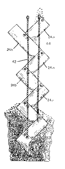
Ladder 10 is formed of a plurality of chute sections 22
interconnected to form ~zig~ chutes and "zag" chutes. Each
chute 22 is formed from a generally planar sheet 24 of rubber,
neoprene or other resilient flexible material. Each sheet 24
has an upper edge 26, lower edge 28 and opposing side edges 30,
with side edges 30 being bent back upon each other to form a
generally U-shaped chute. Anl arcuate notch 32 is formed in
lower edge 28, as shown in Figure 5.
A set of four apertures are formed in each upper corner of
sheets 24, and arranged in first and second pairs 34a and 34b.
Each lower corner of sheets 24 has an aperture 36 therein, with
a series of three apertures 38a, 38b and 38c arranged radially

2045~4~3
therefrom. Each sheet is then bent into a U-shaped chute, and
connected end-to-end to form a zigzag ladder.
Referring to Figure 6, one pair of apertures 34a in the
upper end of sheet 24b are connected to aperture 36 and one of
apertures 38a, b, or c of sheet 24a, with removable fasteners
40. Sheet 24a may be fastened with the lower edge 28 located
deeper within the chute 22 formed by sheet 24b by connecting
apertures 36 and 38 with the second pair of apertures 34b, so as
to reduce the fall of grain from upper sheet 24a to the next
lower sheet 24b. In addition, the slope of each chute 22 may be
adjusted so as to vary the rate at which the grain travels
through ladder lO, utilizing radially spaced apertures 38a, b,
and c. As shown in broken lines in Figure 6, connection of
apertures 36 and 38b with apertures 34a, will render the slopes
of chutes 22 more horizontal than the solid line setting
utilizing apertures 36 and 38a. A further reduction in slope
may be accomplished by utilizing apertures 38c with aperture 36.
In this fashion, each sheet 24a forms a nzign and each sheet
24b forms a ~zagN, to create a zigzag ladder lO, as shown in
Figures 3 and 4. A chain 42 is connected to fasteners 40 of the
lower ends of each ~zig~ chute 24a, to support ladder lO within
a storage facility. A second chain 44 is connected to the upper
ends of each chute 24a, to further support ladder lO and retain

204~iZ~;~
chutes 22 in their zigzag relationship.
In operation, ladder 10 is formed by connecting zig and zag
chutes 24a and 24b in the desired shapes and to form the desired
vertical length. The upper ends of chains 42 and 44 may be
connected together, as shown in Figure 2, to permit hanging of
the ladder from a support at the upper end of storage facility
16 or auger 18.
Whereas the invention has been shown and described in
connection with the preferred embodiment thereof! it will be
understood that many modifications, substitutions and additions
may be made which are within the intended broad scope of the
appended claims. There has therefore been shown and described
an improved ladder for lowering fragile commodities which
accomplishes at least all of the above-stated objects.

Representative Drawing
A single figure which represents the drawing illustrating the invention.
Administrative Status

2024-08-01:As part of the Next Generation Patents (NGP) transition, the Canadian Patents Database (CPD) now contains a more detailed Event History, which replicates the Event Log of our new back-office solution.

Please note that "Inactive:" events refers to events no longer in use in our new back-office solution.

For a clearer understanding of the status of the application/patent presented on this page, the site Disclaimer , as well as the definitions for Patent , Event History , Maintenance Fee  and Payment History  should be consulted.

Event History

Description Date
Time Limit for Reversal Expired 2009-06-22
Letter Sent 2008-06-23
Grant by Issuance 1996-04-23
Application Published (Open to Public Inspection) 1992-05-29
All Requirements for Examination Determined Compliant 1992-04-24
Request for Examination Requirements Determined Compliant 1992-04-24

Abandonment History

There is no abandonment history.

Fee History

Fee Type Anniversary Year Due Date Paid Date
MF (patent, 6th anniv.) - small 1997-06-23 1997-05-26
MF (patent, 7th anniv.) - small 1998-06-22 1998-06-01
MF (patent, 8th anniv.) - small 1999-06-21 1999-06-21
MF (patent, 9th anniv.) - small 2000-06-21 2000-05-23
MF (patent, 10th anniv.) - small 2001-06-21 2001-06-07
MF (patent, 11th anniv.) - small 2002-06-21 2002-05-16
MF (patent, 12th anniv.) - small 2003-06-23 2003-06-12
Reversal of deemed expiry 2004-06-21 2004-05-17
MF (patent, 13th anniv.) - small 2004-06-21 2004-05-17
MF (patent, 14th anniv.) - small 2005-06-21 2005-05-09
2005-05-09
MF (patent, 15th anniv.) - small 2006-06-21 2006-05-05
2006-05-05
MF (patent, 16th anniv.) - standard 2007-06-21 2007-05-07
Owners on Record

Note: Records showing the ownership history in alphabetical order.

Current Owners on Record
THEODORE J. DUNNIGAN
Past Owners on Record
None
Past Owners that do not appear in the "Owners on Record" listing will appear in other documentation within the application.
Documents

To view selected files, please enter reCAPTCHA code :


To view images, click a link in the Document Description column. To download the documents, select one or more checkboxes in the first column and then click the "Download Selected in PDF format (Zip Archive)" or the "Download Selected as Single PDF" button.

List of published and non-published patent-specific documents on the CPD .

If you have any difficulty accessing content, you can call the Client Service Centre at 1-866-997-1936 or send them an e-mail at CIPO Client Service Centre.


Document
Description 
Date
(yyyy-mm-dd) 
Number of pages   Size of Image (KB) 
Claims 1993-12-04 2 62
Cover Page 1993-12-04 1 13
Abstract 1993-12-04 1 25
Drawings 1993-12-04 4 98
Description 1993-12-04 5 180
Abstract 1996-04-23 1 24
Cover Page 1996-04-23 1 16
Description 1996-04-23 5 163
Claims 1996-04-23 2 58
Drawings 1996-04-23 4 103
Representative drawing 1999-07-02 1 26
Maintenance Fee Notice 2008-08-04 1 171
Fees 1996-05-29 1 50
Fees 1995-06-02 1 43
Fees 1994-05-31 1 59
Fees 1993-06-15 1 21
Prosecution correspondence 1991-06-21 5 135
Prosecution correspondence 1994-12-16 8 293
Courtesy - Office Letter 1992-06-08 1 38
Prosecution correspondence 1992-04-24 1 26
PCT Correspondence 1996-01-31 1 38
Examiner Requisition 1994-06-30 1 52