Sélection de la langue

Search

Sommaire du brevet 2045243 

Énoncé de désistement de responsabilité concernant l'information provenant de tiers

Une partie des informations de ce site Web a été fournie par des sources externes. Le gouvernement du Canada n'assume aucune responsabilité concernant la précision, l'actualité ou la fiabilité des informations fournies par les sources externes. Les utilisateurs qui désirent employer cette information devraient consulter directement la source des informations. Le contenu fourni par les sources externes n'est pas assujetti aux exigences sur les langues officielles, la protection des renseignements personnels et l'accessibilité.

Disponibilité de l'Abrégé et des Revendications

L'apparition de différences dans le texte et l'image des Revendications et de l'Abrégé dépend du moment auquel le document est publié. Les textes des Revendications et de l'Abrégé sont affichés :

  • lorsque la demande peut être examinée par le public;
  • lorsque le brevet est émis (délivrance).
(12) Brevet: (11) CA 2045243
(54) Titre français: ECHELLE POUR PARTICULES FRAGILES
(54) Titre anglais: LADDER FOR FRAGILE PARTICULATE COMMODITIES
Statut: Périmé et au-delà du délai pour l’annulation
Données bibliographiques
(51) Classification internationale des brevets (CIB):
  • B65G 11/08 (2006.01)
(72) Inventeurs :
  • DUNNIGAN, THEODORE J. (Etats-Unis d'Amérique)
(73) Titulaires :
  • THEODORE J. DUNNIGAN
(71) Demandeurs :
(74) Agent: SMART & BIGGAR LP
(74) Co-agent:
(45) Délivré: 1996-04-23
(22) Date de dépôt: 1991-06-21
(41) Mise à la disponibilité du public: 1992-05-29
Requête d'examen: 1992-04-24
Licence disponible: S.O.
Cédé au domaine public: S.O.
(25) Langue des documents déposés: Anglais

Traité de coopération en matière de brevets (PCT): Non

(30) Données de priorité de la demande:
Numéro de la demande Pays / territoire Date
07/619,083 (Etats-Unis d'Amérique) 1990-11-28

Abrégés

Abrégé anglais


An apparatus for lowering particulate commodities includes a
vertically disposed ladder extending from the upper end of the
storage facility to the lower end of the storage facility. The
ladder is formed of flexible planar sheets bent upon themselves
to define substantially U-shaped chute member formed into a
zigzag pattern such that the particulate commodities flow
downward through the chute members passing from one chute member
to the next chute member. The chute members are connected such
that an opening is formed at the upper end of each chute member
so that the commodities may exit the ladder once the level of
the commodity within the storage facility has reached the upper
end of a particular chute member.

Revendications

Note : Les revendications sont présentées dans la langue officielle dans laquelle elles ont été soumises.


The embodiments of the invention in which an exclusive
property or privilege is claimed are defined as follows:
1.
An apparatus for lowering fragile, particulate commodities into a commodity
storage facility, comprising:
a vertically disposed ladder means having upper and lower ends;
means for supporting said ladder means within the storage facility so that the lower end
thereof is positioned adjacent the lower end of the storage facility,
the upper end of said ladder means being in communication with a source of
commodities;
said ladder means comprising a plurality of resilient, flexible planar sheets, each of said
sheets being bent upon itself to define a substantially U-shaped chute member
having upper and lower ends;
the lower end of each chute member, except the lowermost chute member, being
secured to the upper end of the chute member positioned therebelow, adjacent
chute members being oppositely disposed with respect to one another to define
a zigzag pattern, whereby the particulate commodities will flow downward
through said chute members passing from one chute member to the next chute
member positioned therebelow;
adjacent chute members defining an opening at the connection therebetween whereby
the particulate commodities may exit the ladder therethrough once the level of
commodity within the storage facility has reached that level.
- 6 -

2.
The apparatus of claim 1, further comprising means for
selectively, adjustably securing the lower ends of the chute
members to the upper ends of the chute members positioned
therebelow, so as to selectively adjust the slope of each chute
member in the zigzag pattern, whereby the speed at which a
commodity passes through said ladder means may be adjusted.
3.
The apparatus of claim 1, wherein said means for supporting
said ladder means within the storage facility includes a
flexible chain means connected to the upper ends of parallel
chute members defining the "zig" portion of the zigzag pattern.
4.
The apparatus of claim 3, wherein said means for supporting
said ladder means within the storage facility further includes
chain means connected to the upper ends of the parallel chutes
forming the "zag" portion of the zigzag pattern.
7 -

Description

Note : Les descriptions sont présentées dans la langue officielle dans laquelle elles ont été soumises.

Technical Field 20~S243
The present invention relates generally to a ladder for
lowering fragile, particulate commodities into a storage
facility, and more particularly to a ladder which may remain in
5place within the storage facility during loading of the
facility.
~ackqround of the Invention
Zigzag shaped chutes have long been utilized to lower fruits
and vegetables from an upper level to a lower level, to avoid
10damaging the commodities. The falling speed of the commodities
is reduced by frequently changing the direction that the
commodity is falling within the chute.
One problem with prior art zigzag chutes is in the need to
remove the chute as the storage facility is filled with the
15commodity, to prevent damage to the chute under the pressure of
the commodity within the storage facility. To avoid damage to
the chute, prior art chutes are designed to be progressively
raised with the level of the commodity in the facility.
However, this capability complicates the structure of the chute,
20requiring additional time and labor in construction, and adding
to the overall weight of the finished chute.
It is therefore a general object of the present invention to
provide an improved ladder for lowering fragile commodities
within a storage facility.
25Another object is to provide a ladder which is resiliently
collapsible so that it may remain in a storage facility after
filling of the facility, and yet be reusable.
A further object of the present invention is to provide a
ladder whicll is light weight, simple in operation and economical
30to manufacture.
Yet another object is to provide a ladder which is
adjustable to cause different flow rates of commodities
therethrough.

2045243
These and other objects of the present invention will be
apparent to those skilled in the art.
Summary of the Invention
The apparatus for lowering particulate commodities into a
storage facility includes a vertically disposed ladder extending
from the upper end of the storage facility to the lower end of
the storage facility. The ladder is formed of flexible planar
sheets bent upon themselves to define substantially U-shaped
cllute member formed into a zigzag pattern such that the
particulate commodities flow downward through the chute members
passing from one chute member to the next chute member. The
chute members are connected such that an opening is formed at
the upper end of each chute member so that the commodities may
exit the ladder once the level of the commodity within the
storage facility has reached the upper end of a particular chute
member.
Brief Description of the Drawinqs
Figure 1 is a sectional view through a storage facility
showing the ladder of the present invention in operating
- pOsition;
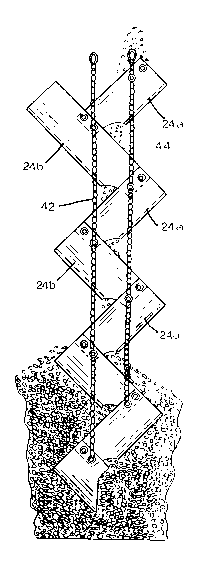
Figure 2 is an enlarged prospective view of the ladder of
this invention;
Figure 3 is an enlarged view of Figure 1, showing grain
being lowered through the ladder;
Figure 4 is a view similar to Figure 3, after the storage
facility has been partially filled;
Figure 5 is a perspective of two sections of the ladder,
prior to being positioned to form chute sections: and
Figure 6 is a view of a portion of the ladder formed by the

;~)'15~43
chute sections of Figure 5.
Description of the Preferred Embodiment
Referring now to the drawings, in which similar or
corresponding parts are identified with the same reference
numerals, and more particularly to Figure 1, the ladder of the
present invention is designated generally at 10 and extends from
the open upper end 12 to the lower end 14 of a storage facility
16. An auger 18 or other conveyor conveys grain 20 (seen in
Figures 3 and 4) or other commodities to the upper end of ladder
10 and storage facility 16. Preferably, ladder 10 is utilized
with fragile particulate commodities, such as beans or the like.
Ladder 10 is formed of a plurality of chute sections 22
interconnected to form ~zig~ chutes and "zag" chutes. Each
chute 22 is formed from a generally planar sheet 24 of rubber,
neoprene or other resilient flexible material. Each sheet 24
has an upper edge 26, lower edge 28 and opposing side edges 30,
with side edges 30 being bent back upon each other to form a
generally U-shaped chute. Anl arcuate notch 32 is formed in
lower edge 28, as shown in Figure 5.
A set of four apertures are formed in each upper corner of
sheets 24, and arranged in first and second pairs 34a and 34b.
Each lower corner of sheets 24 has an aperture 36 therein, with
a series of three apertures 38a, 38b and 38c arranged radially

2045~4~3
therefrom. Each sheet is then bent into a U-shaped chute, and
connected end-to-end to form a zigzag ladder.
Referring to Figure 6, one pair of apertures 34a in the
upper end of sheet 24b are connected to aperture 36 and one of
apertures 38a, b, or c of sheet 24a, with removable fasteners
40. Sheet 24a may be fastened with the lower edge 28 located
deeper within the chute 22 formed by sheet 24b by connecting
apertures 36 and 38 with the second pair of apertures 34b, so as
to reduce the fall of grain from upper sheet 24a to the next
lower sheet 24b. In addition, the slope of each chute 22 may be
adjusted so as to vary the rate at which the grain travels
through ladder lO, utilizing radially spaced apertures 38a, b,
and c. As shown in broken lines in Figure 6, connection of
apertures 36 and 38b with apertures 34a, will render the slopes
of chutes 22 more horizontal than the solid line setting
utilizing apertures 36 and 38a. A further reduction in slope
may be accomplished by utilizing apertures 38c with aperture 36.
In this fashion, each sheet 24a forms a nzign and each sheet
24b forms a ~zagN, to create a zigzag ladder lO, as shown in
Figures 3 and 4. A chain 42 is connected to fasteners 40 of the
lower ends of each ~zig~ chute 24a, to support ladder lO within
a storage facility. A second chain 44 is connected to the upper
ends of each chute 24a, to further support ladder lO and retain

204~iZ~;~
chutes 22 in their zigzag relationship.
In operation, ladder 10 is formed by connecting zig and zag
chutes 24a and 24b in the desired shapes and to form the desired
vertical length. The upper ends of chains 42 and 44 may be
connected together, as shown in Figure 2, to permit hanging of
the ladder from a support at the upper end of storage facility
16 or auger 18.
Whereas the invention has been shown and described in
connection with the preferred embodiment thereof! it will be
understood that many modifications, substitutions and additions
may be made which are within the intended broad scope of the
appended claims. There has therefore been shown and described
an improved ladder for lowering fragile commodities which
accomplishes at least all of the above-stated objects.

Dessin représentatif
Une figure unique qui représente un dessin illustrant l'invention.
États administratifs

2024-08-01 : Dans le cadre de la transition vers les Brevets de nouvelle génération (BNG), la base de données sur les brevets canadiens (BDBC) contient désormais un Historique d'événement plus détaillé, qui reproduit le Journal des événements de notre nouvelle solution interne.

Veuillez noter que les événements débutant par « Inactive : » se réfèrent à des événements qui ne sont plus utilisés dans notre nouvelle solution interne.

Pour une meilleure compréhension de l'état de la demande ou brevet qui figure sur cette page, la rubrique Mise en garde , et les descriptions de Brevet , Historique d'événement , Taxes périodiques et Historique des paiements devraient être consultées.

Historique d'événement

Description Date
Le délai pour l'annulation est expiré 2009-06-22
Lettre envoyée 2008-06-23
Accordé par délivrance 1996-04-23
Demande publiée (accessible au public) 1992-05-29
Toutes les exigences pour l'examen - jugée conforme 1992-04-24
Exigences pour une requête d'examen - jugée conforme 1992-04-24

Historique d'abandonnement

Il n'y a pas d'historique d'abandonnement

Historique des taxes

Type de taxes Anniversaire Échéance Date payée
TM (brevet, 6e anniv.) - petite 1997-06-23 1997-05-26
TM (brevet, 7e anniv.) - petite 1998-06-22 1998-06-01
TM (brevet, 8e anniv.) - petite 1999-06-21 1999-06-21
TM (brevet, 9e anniv.) - petite 2000-06-21 2000-05-23
TM (brevet, 10e anniv.) - petite 2001-06-21 2001-06-07
TM (brevet, 11e anniv.) - petite 2002-06-21 2002-05-16
TM (brevet, 12e anniv.) - petite 2003-06-23 2003-06-12
Annulation de la péremption réputée 2004-06-21 2004-05-17
TM (brevet, 13e anniv.) - petite 2004-06-21 2004-05-17
TM (brevet, 14e anniv.) - petite 2005-06-21 2005-05-09
2005-05-09
TM (brevet, 15e anniv.) - petite 2006-06-21 2006-05-05
2006-05-05
TM (brevet, 16e anniv.) - générale 2007-06-21 2007-05-07
Titulaires au dossier

Les titulaires actuels et antérieures au dossier sont affichés en ordre alphabétique.

Titulaires actuels au dossier
THEODORE J. DUNNIGAN
Titulaires antérieures au dossier
S.O.
Les propriétaires antérieurs qui ne figurent pas dans la liste des « Propriétaires au dossier » apparaîtront dans d'autres documents au dossier.
Documents

Pour visionner les fichiers sélectionnés, entrer le code reCAPTCHA :


Pour visualiser une image, cliquer sur un lien dans la colonne description du document. Pour télécharger l'image (les images), cliquer l'une ou plusieurs cases à cocher dans la première colonne et ensuite cliquer sur le bouton "Télécharger sélection en format PDF (archive Zip)" ou le bouton "Télécharger sélection (en un fichier PDF fusionné)".

Liste des documents de brevet publiés et non publiés sur la BDBC .

Si vous avez des difficultés à accéder au contenu, veuillez communiquer avec le Centre de services à la clientèle au 1-866-997-1936, ou envoyer un courriel au Centre de service à la clientèle de l'OPIC.


Description du
Document 
Date
(aaaa-mm-jj) 
Nombre de pages   Taille de l'image (Ko) 
Revendications 1993-12-04 2 62
Page couverture 1993-12-04 1 13
Abrégé 1993-12-04 1 25
Dessins 1993-12-04 4 98
Description 1993-12-04 5 180
Abrégé 1996-04-23 1 24
Page couverture 1996-04-23 1 16
Description 1996-04-23 5 163
Revendications 1996-04-23 2 58
Dessins 1996-04-23 4 103
Dessin représentatif 1999-07-02 1 26
Avis concernant la taxe de maintien 2008-08-04 1 171
Taxes 1996-05-29 1 50
Taxes 1995-06-02 1 43
Taxes 1994-05-31 1 59
Taxes 1993-06-15 1 21
Correspondance de la poursuite 1991-06-21 5 135
Correspondance de la poursuite 1994-12-16 8 293
Courtoisie - Lettre du bureau 1992-06-08 1 38
Correspondance de la poursuite 1992-04-24 1 26
Correspondance reliée au PCT 1996-01-31 1 38
Demande de l'examinateur 1994-06-30 1 52