Note: Descriptions are shown in the official language in which they were submitted.
~ ~ 204558~
SPECIFICATION
Fluidized Bed Gas Dispersing Device
(Technical Field)
The present invention relates to a Eluidized bed
gas dispersing device for use with a fluidized bed
preliminary reducing furnace for iron ore, chrome ore,
etc.
(Background Art~
In metal ore resources inclusive of iron ore, a
proportion of massive ore tends to decrease, and a
proportion of powdery ore tends to increase. At
present, concentration such as flotation or magnetic
separation is positively developed, so as to improve a
grade of a low-grade ore in particular. Accordingly,
such a tendency as mentioned above is anticipated to be
~marked more and more later.
There has been recently developed a so-called
melt reduction process for producing a molten metal
directly from a powdery ore. The melt reduction process
comprises the steps of preliminarily reducing the
powdery ore in a fluidized bed preliminary reducing
furnace, then introducing the preliminarily reduced
powdery ore obtained above into a melt reducing furnace
2045~8~
filled with a carbonaceous solid reducing agent, and
reducing and liquefying the preliminarily reduc~ed
powdery ore in the melt reducing furnace to produce the
molten metal.
In the case that an inner diameter of the
fluidized bed preliminary reducing furnace is large, a
gas flow in a fluidizçd bed becomes nonuniform to cause
a difficulty of proper fluidization. Therefore, in
order to obtain a uniform gas flo~, a gas dispersing
plate having many gas dispersing holes is provided at a
lower portion of the furnace where an inlet of a
reducing gas is formed.
In the case of utilizing a high-temperature gas
generated in the melt reducing furnace as the reducing
gas for fluidization, there is a problem that the gas
dispersing holes of the gas dispersing plate are closed
by a large amount of dust contained in the high-
temperature gas generated from the melt reducing
furnace.
A solution of this problem is disclosed in
Japanese Utility Model Laid-open Publication No. 62-
29094, for example. Fig. 4 shows a fluidized bed gas
dispersing device disclosed in this prior art.
Referring to Fig. 4, reference numeral 3 generally
-2-
~0~5~4
designates this fluidized bed gas dispersing device
provided in a preliminary reducing furnace 1. The
dispersing device 3 is constructed of a plurality of
bars 2 movable in a longitudinal direction thereof,
which bars 2 are arranged in upper and lower horizontal
planes so as to intersect with each other as viewed in
plan. In removing a deposited substance 12 such as dust
deposited on a surface of each bar 2, the bar 2 is
sometimes drawn off, and the deposited substance 2 is
then squeezed off.
However, this prior art device has a defect that
the bars are deformed by heat to re~ult in impossibility
of drawing of the bars.
Further, the present applicant has proposed in
Japanese Patent Laid-open Publication No. 59-107185 a
technique such that deformed bars arranged in rows are
~otated to change an opening size between the adjacent
ores of the deformed bars.
Thus, this technique is intended to change the
opening size between the adjacent deformed bars.
However, it is not intended to prevent the opening
between the bars from being closed by the dust.
(Summary of the invention)
~û4~84
It is an object of the present invention to
provide a fluidized bed gas dispersing device which can
prevent the thermal deformation of the bars and also
prevent the blinding of the gas dispersing plate due to
the dust, thereby extending a life of the bars and
stabilizing the fluidized bed.
The fluidized bed gas dispersing device
according to the present invention comprises a grate
consisting of a plurality of rotatable bars each having
a circular cross section, said bars being vertically
arranged in rows in a plurality of horizontal planes in
such a manner that said bars in the adjacent ones of
said horizontal planes intersect each other, an~ a
rotating device for rotating each of said bars.
The bars in the adjacent ores of the horizontal
planes may intersect each other at right angles or
oblique angles as viewed in plan.
It is preferable that an opening ratio of the
grace is 2 - 10 %.
The rotating device may be comprised of a pinion
fixed to an end portion of each bar, a rack meshing with
the pinion, and a power cylinder for reciprocating the
rack.
~ ` 2045584
The rotating device may be comprised of a sprocket
fixed to an end portion of each bar, a chain wrapped around the
sprocket, and a motor for driving the chain.
The rotating device is preferably constructed as a
continuous rotating device. In this case, a rotation speed of
each bar to be rotated by the continuous rotating device is
preferably set in the range of 0.1 - 3.0 rpm.
The rotating device may be constructed as an
intermittent rotating device.
In a broad aspect, therefore, the present invention
relates to a fluidized bed gas dispersing device for a fluidized
bed preliminary reducing furnace, comprising: a furnace housing;
a first planar grid disposed within said housing and having a
first series of regularly spaced parallel bars, said bars each
having a circular cross-section; a second planar grid disposed
within said housing and having a second series of regularly
spaced parallel bars, said bars each having a circular cross-
section, the planar aspect of said second grid being proximately
disposed in parallel relation to the planar aspect of said first
grid, said bars of said first and second grids being spaced apart
to maintain a non-variable gas flow slit area between bars during
rotation of said bars; and means for rotating each of said bars
of said first and second grids to remove dust accumulation on the
bars and to prevent heat deformation of the bars.
Fig. 1 shows a first preferred embodiment of the
present invention, wherein Fig. l(a) is a vertical sectional view
of a dispersing plate constructed of two stages of plural
moveable bars, and Fig. l(b) is a side view of a rotating device
for the movable bars shown in Fig. l(a); Fig. 2 shows a second
preferred embodiment of the present invention, wherein Fig. 2(a)
is a vertical sectional view of a dispersing plate constructed
of three stages of plural movable bars, and Fig. 2(b) is a side
view of a rotating device for the movable bars shown in Fig.
2(a); Fig. 3 is a graph showing the operation of the present
invention; and Fig. 4 is a vertical
~ ` - 2 0 ~ 8 ~!
sectional view of the fluidized bed gas dispersing
device in the prior art.
(Best Mode for Embodying the invention)
According to the present invention, each bar i8
rotated. The rotation of the bar is advantageous for
the following reasons.
(1) A load of powdery ore is placed on the bar
in a sectional direction thereof. Further, when a
difference in temperature distribution of the ~ar is
generated, the bar is deformed. However, by rotating
the bar, the load and the difference in temperature
distribution can be averaged to thereby prevent the
deformation of the bar.
(2) A dust contained in an introduced reducing
gas and particles falling from a fluidized bed are
deposited onto the bar. In the case that the bar is at
rest, the dust and the particles are deposited onto
upper and lower surfaces of the bar rather than side
surfaces thereof dependently on the reducing gas rising
in the furnace. However, by rotating the bar, the
deposition o~ the dust and the particles onto the entire
surface of the bar is avoided.
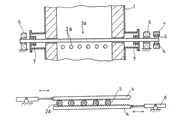
Fig. 1 shows a first preferred embodiment of the
presbnt invention. More specifically, Fig. (a) shows a
2~5S8~
dispersing plate 3a constructed of two stages of plural
movable bars 2a arranged in rows, and Fig. (b) shows a
rotating device for the movable bars 2a shown in Fig.
l(a).
As shown in Figs. l(a) and l(b), each movable
bar 2a extends through a pair of gas seals 7 out of a
preliminary reducing furnace 1, and is rotatably
supported at opposite end portions thereof to a pair of
bearings 6 provided outside the furnace 1. The movable
bars 2a are rotated by the rotating device such that a
pinion 5 is fixedly mounted on each movable bar 2a at
its one end, and a pair of upper and lower racks 4
meshing with the pinions 5 are reciprocally moved by a
pair of right and left cylinders 8.
Fig. 2 shows a second preferred embodiment of
the present invention. More specifically, Fig~ 2(a)
shows a dispersing plate 3a constructed of three stages
of plural movable bars 2a arranged in rows, and Fig.
2(b) shows a rotating device for the movable bars 2a
shown in Fig. 2(a).
In the second preferred embodiment, the rotating
device for each movable bar 2a is constructed of
sprockets 10 fixedly mounted on each movable bar 2a at
its opposite end portions, chains 9 wrapped around the
204~4
sprockets 10, and motors 11 for driving the chains 9.
Alternatively, belts and pulleys may be substituted for
the chains 9 and the sprockets 10.
Fig. 3 is a graph showing the operation of the
present invention.
Referring to Fig. 3, the axis of abscissa
represents a rotational speed of the bar, and the axis
of ordinate represents a deposited substance removing
rate. The deposited substance removing rate is defined
by the following e~uation. Deposited Substance Removing
Rate = [(tl - to)/tl] x 100 % where, to (mm) represents a
thickness of a deposited substance deposited onto the
bar for a week in the case that the bar is rotated
during the operation, and tl (mm) represents a thickness
of the deposited substance deposited onto the bar for a
week in the case that the bar is not rotated during the
operation.
The graph shown in Fig. 3 is a relation between
the rotational speed of the bar and the deposited
substance removing rate in the case that the rotation of
the bar is continuous. As apparent from Fig. 3, when
the rotations speed is less than 0.1 rpm, the effects
mentioned above in Paragraphs (1) and (2) are not
exhibited, while when the rotations speed exceeds 3.0
2 ~ 4 ~
rpm, the effects are saturated to uselessly increase a
power cost.
Accordingly, the rotations speed i8 preferably
set to 0.1 - 3.0 rpm in the case of continuously
rotating the bar.
Some examples according to the above preferred
embodiments will now be described.
(1) The dispersing device according to the first
preferred embodiment was operated under the following
conditions.
Diameter of the bar: 40 mm
Length of the bar: 1200 mm
Material of the bar: Heat resisting alloy
Rotational speed of the bar: 2.0 rpm
Atmospheric temperature: 980C
Atmospheric as composition: H2O 20 %
CO 45 %
N2 34 %
trace gas 1 ~
One to be reduced: Iron ore (particle size: 5
mm or less)
As a result of this operation, no deposited
substance was generated on the bar, and a life of the
_g_
~045~84
bar was extended up to six months in comparison with one
month in the prior art.
(2) The dispersing device according to the
second preferred embodiment was operated under the
ollowing conditions.
Diameter of the bar: 30 mm
Length of the bar: 1800 mm
Materia of the bar: Heat resisting alloy
Rotations speed of the bar: 1.0 rpm
Atmospheric temperature: 1030C
Atmospheric gas composition: H217 %
H2O0.6 %
CO32 %
CO21 %
N249 ~
trace gas 0.4 %
Vertically projected area of opening defined by
the bars: 35 x 35 mm
As a result of this operation, no deposited
substance was generated even when the dispersing plate
was used for a year. In contrast, a life of the
conventions dispersing plate was one month in average,
and in the worst case, a deposited substance was
--10--
21~5~84
generated in about six days to close the openings of the
dispersing plate.
According to the present invention, the
following excellent effects are exhibited.
(1) The deformation of the bar is avoided to
thereby extend a life of the bar.
(2) The deposited substance on the bar can be
removed to thereby effectuate a stable condition of a
fluidized bed.
Further, in the case of intermittently rotating
the bars, it is preferable to rotate the bars every 5 -
10 seconds. The opening ratio of the dispersing device
is defined as a ratio of the projected opening area of
the dispersing device to the total plane area thereof.
While the opening ratio is normally 2 - 5 % in a
fluidizing device for fine particles, it is preferably
~set in the range of 2 - 10 % from the viewpoints of
prevention of closing o~ the dispersing device and
prevention of falling of the particles through the
dispersing device.