Note: Descriptions are shown in the official language in which they were submitted.
2046403
- G-7141
C-4272
OPTICAL FI}~ER T~Tl~T- AND T~l2~T~TION METHOD
BAC~tGROUND OF TRE INVENTION
This invention relates generally to fiber optic
connectors and, more specifically, to fiber optic
connectors in which a plastic fiber end is formed by a
melting process.
Plastic optical fibers used for data transmission are
most often supplied in cable form in which the cable
comprises a glass or plastic fiber core, a thin cladding,
and a protective jacket which can include strengthening
members. Connecting the fiber optic cable to another
device, such as an electro-optic device or another cable,
can be accomplished by two methods.
In one, bare fiber ends are contacted without any
added terminal. This is a very delicate connection and is
subject to damage if the connection, with attendant signal
degradation across the interface.
The other method provides a terminal on the fiber end.
This arrangement is very durable and provides a more
reliable connection in systems requiring quick
connect/disconnect with devices or other cables. The
termination of the cable is often performed as a field
operation, such as when installing data transmission
systems, such as computer LANs (Local Area Networks).
To provide an optically efficient interface between an
optical fiber and another device, it is necessary to mount
the fiber end in a suitable terminal fitting in a manner
that will provide good signal transmission across the
interface. This requires that the fitting properly align
the fiber with the terminal of other device. Such
alignment is provided by mating surfaces formed on the
fittings for the fiber and the device, which interfit to
assure alignment.
An optically efficient interface also requires that
the fiber have a flat, smooth end surface. Two methods of
forming this end surface on plastic optic fibers during
,1' ~
2046403
termination are in general usage. In both, the fiber end
is exposed and a terminal is clamped or crimped onto the
cable jacket, or the bare fiber is epoxied or otherwise
cemented onto the terminal. The terminal can be a ferrule
or a multiple fiber or combined fiber and electrical
connector.
In one, the "polishing" method, the fiber end is
snipped off to form a generally flat surface near the
terminal face of the end fitting. This surface is then
polished to a predetermined degree of smoothness to
eliminate pits which adversely affect light transmission.
This polishing method is a laborious, exacting and, thus
costly, process which requires repeated visual inspection
to determine when the predetermined degree of smoothness is
achieved.
The third "hot plate" method involves stripping the
cable jacket, inserting the fiber into an end fitting and
projecting it through the exit aperture beyond the terminal
face of the fitting. The fiber end is then snipped off a
predetermined short distance beyond the terminal face, a
smooth plate is brought into contact with the fiber end,
heat is applied to the plate to melt the fiber, the heat is
removed from the plate, the fiber cools and solidifies, and
the plate is removed. This "hot plate" method leaves the
fiber end with the same smooth, flat surface as the plate.
One problem with the hot plate method is disposal of
the excess reflowed fiber material, which remains after
melting, in a manner that does not adversely affect light
transmission through the terminal. Several methods are in
current usage. In one, the excess reflowed material
resulting from the melting is formed into a smooth-surfaced
"pancake" lying atop the fitting's terminal face. While
this provides the requisite smooth, flat surface, this
pancake protrudes from the surface and is unbounded, which
allows light leakage and degrades light transmission to an
unacceptable degree.
Another problem is caused by the thickness of this
2046~03
pancake. Since it is uncontrolled, it prevents precise
mating of the terminal with the other device. This affects
alignment of the fiber with the other device and light
transmission across the interface.
A further problem is contamination of the fiber
material by the cladding material, caused by their
intermixing during melting. This further degrades light
transmission.
Two design modifications of the end fitting have been
made in an effort to overcome the problems caused by the
protruding, unbounded pancake. In one, the thickness of
the pancake is reduced by flaring the exit aperture with a
conical countersink. If the excess reflowed material
exceeds the capacity of this slight enlargement, a
protruding pancake is formed, with the same problems just
described.
If melting produces insufficient excess reflowed
material to completely fill the flared enlargement, the hot
plate will make incomplete contact and form a pitted fiber
end surface, resulting in seriously degraded light
transmission. In either event, the cladding material will
again contaminate the core material during melting, with
the resulting adverse consequences noted above.
In the other modification, the protruding pancake is
eliminated by moving it subsurface. The exit aperture is
countersunk to form an enlarged cylindrical recess in the
fitting terminal face. Upon melting, the pancake is formed
completely within the recess. A smooth surface may be
formed by the hot plate, regardless of the quantity of the
excess reflowed material. The mating and alignment
problems caused by the protruding pancake lying atop the
terminal face of the fitting are eliminated.
However, a shortage of material (i.e. insufficient to
fill the recess) will result in an irregular boundary,
resulting in signal degradation. Although the enlarged
recess prevents formation of a protrusion, it still can
cause light leakage due to the lack of a defined lack of a
2046403
boundary if the reflowed plastic material does not reach
the recess walls.
The hot plate melting results in a gap between the
melted fiber end surface (top of the pancake) and the point
of fiber entrance to the recess if the recess is not
exactly filled, which it never is. In order to guarantee
that the pancake does not protrude above the terminal face,
this recess must be sufficiently voluminous to accommodate
the largest quantity of excess reflowed material that could
occur. Thus the gap is inevitable. In any event the ideal
light guiding properties if the fiber are lost at the
entrance to the recess where the irregular pancake of
melted material begins.
When the fitting is mated with the other device, the
gap introduces a new source of light leakage and signal
degradation. Also, the problem of contamination by the
intermixed cladding material persists.
All of the currently-used methods and apparatus for
terminating an optical fiber have inherent physical
problems that require extremely tight processing tolerances
to minimize degradation of light transmission across the
terminal interface in a connection. A slight variance of
excess melted fiber material will cause light leakage that
results in signal degradation and consequent inferior light
transmission at the terminal interface.
Thus, a need exists for an optical fiber termination
method and apparatus which eliminates the problems causing
light leakage and resultant signal degradation.
~UNMARY OF THB INVBNTION
It is an object of this invention to provide an
optical fiber termination method and apparatus which
eliminates the problems causing light leakage and resultant
signal degradation.
It is another object of this invention to provide an
improved terminal fitting for the end of an optical fiber
- 1 20~6403
that eliminates the causes of light leakage characteristic
of currently-used fittings.
It is a further object of this invention to provide an
improved fiber optic terminal featuring reduced light
leakage resulting from the use of a terminal fitting that
enables hot plate melting to provide a fiber end surface
coplanar with the fitting end face.
It is a yet further feature of this invention to
provide an improved fiber optic terminal which permits
relaxation of processing tolerances, while providing
optimum light coupling and transmission properties.
In accordance with one aspect, this invention features
a fitting for the end of a light-transmitting fiber,
comprising a body, a cavity in the body for receiving a
fiber, and a planar terminal face formed on the end of the
body and containing an exit aperture for the fiber. A
reservoir groove is formed in the terminal face surrounding
the exit aperture for receiving the excess reflowed
material resulting from melting of the fiber to form a
smooth end face. The groove is spaced from the exit
aperture by a portion of the terminal face. The groove is
dimensioned to completely receive subsurface the excess
reflowed fiber material resulting from the hot plate
melting.
In another aspect, this invention features a fiber
optic connector comprising a fiber having a planar end
surface formed by hot plate melting, a terminal fitting
surrounding the fiber and having a terminal face coplanar
with the fiber end surface, and a reservoir groove formed
in the terminal face surrounding the aperture and being
isolated therefrom by a portion of the terminal face. The
groove is preferably dimensioned to completely receive
subsurface the excess reflowed fiber material resulting
from the hot plate melting. In a preferred embodiment, the
exit aperture is circular and the groove has a coaxial
inner diameter only sufficiently larger than the aperture
diameter to assure isolation of the groove from the
2046403
aperture.
In a further aspect, this invention features a method
of forming a fiber optic terminal, comprising forming an
end fitting having a planar terminal face, forming a
through bore in the fitting terminating in an exit aperture
in the terminal face, and forming a reservoir groove in the
terminal face surrounding the exit aperture and isolated
therefrom. The method further comprises the steps of
inserting the fiber through the bore and beyond the
terminal face, and melting the fiber and forming it
coplanarly with the terminal face, with the excess reflowed
fiber material received within the groove completely below
the terminal face.
In all aspects, this invention eliminates light loss
due to unbounded protrusions extending above the fitting
terminal face, by subsurface gaps, by misalignment, and by
contamination of the fiber core material by cladding
material.
These and further features of this invention will
become more readily apparent upon reference to the
following detailed description and the annexed drawings, in
which:
BRIEF DRAWING DE8CRIPTION
Fig. 1 is a perspective view of a terminal fitting
used in forming a fiber optic terminal in accordance with
this invention;
Fig.2 is a partial longitudinal sectional view, taken
along line 2-2 of Fig. 1, and illustrating a fiber inserted
through the fitting;
Fig. 3 is a view similar to Fig. 2, illustrating the
melting of the fiber end during the formation of the fiber
optic terminal of this invention;
Fig. 4 is a view similar to Fig. 3, illustrating the
terminal after formation;
20~6403
Fig. 5 is an enlarged detail sectional view of the
optic fiber terminated in accordance with this invention;
and
Fig. 6 is a longitudinal sectional view of the
interface of two fiber optic terminals formed in accordance
with this invention.
DBT~T~n DB8CRIPTION OF A PRBFBRRBD ~VRoDINBNT
OF THB INVBNTION
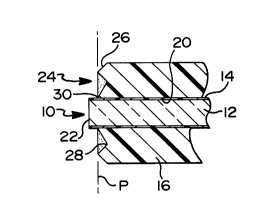
Referring now to Fig. 5 of the drawings, a plastic
optical fiber 10 comprises a core of an optical plastic,
such as polymethylmethacrylate, and a cladding of a
suitable material, such as a fluoropolymer. The fiber core
12 may be of any diameter which suits a particular
application. As an example, the fiber 12 is illustrated as
being on the order of lmm, while the cladding thickness is
on the order of 20 microns.
Both core and cladding are conventionally part of a
fiber optic cable (not shown) that includes one or more
fibers encased in a protective jacket (not shown), which is
conventionally stripped for cable termination. Fiber optic
cables of this type are useful for data transmission and
must be terminated for connection to other cables or to
electro-optical devices.
Fig. 1 shows an elongated fitting, or ferrule, 16
having a base flange 18 and a longitudinal bore 20 for
receiving fiber 10. Ferrule is preferably made of Hytrel~
or other polyester copolymer. Bore 20 terminates in an
exit aperture 22 formed in the terminal face 24 of ferrule
16. Terminal face 24 is bounded by a peripheral chamfer 26
and includes an annular groove 28 intermediate exit
aperture 22 and chamfer 26.
As illustrated in Fig. 2, the axially outermost
portions of terminal face 24, which separates exit aperture
22 from groove 28 and groove 28 from chamfer 26, lie in a
- ' 20~6403
plane denoted "P". In this manner, groove 28 is isolated
from exit aperture 22 by a land, or ring, 30, and from
chamfer 26 by a coplanar land 32.
Formation of the terminal will now be described, with
reference to Figs. 1, 2, 3 and 4. As shown in Fig. 2,
fiber 10 is projected through bore 20 and out exit aperture
22, where it is snipped off a predetermined distance beyond
terminal face 24. This distance should be sufficient to
assure that a solid, or complete, cross-section of core
material 12 extends beyond terminal face 24.
In addition, this distance must be such as to assure
that the volume of fiber material (including both core and
cladding material) is less than the volume of groove 28
lying below plane "P" of terminal face 24 (i.e. the
subsurface volume of groove 28). In practice the
"predetermined" distance will be a range of distances
dependent on the tooling or fixturing and tolerances
utilized in a particular field termination procedure. In
any event, the groove subsurface volume always exceeds the
projecting fiber volume.
As illustrated in Fig. 3, a conventional "hot plate"
34 is contacted with the end of fiber 10 which begins to
melt. Plate 34 has a flat, smooth surface 38 and is heated
to a temperature that is high enough to melt fiber 10, but
is lower than the melting temperature of ferrule 16. The
hot plate 34 advances as the fiber end begins to melt.
This process continues (actually a very short time)
until hot plate 34 engages the terminal face rings 30 and
32. At this time, plate 34 is cooled, allowing the end of
fiber 10 to solidify. Then plate 34 is removed, leaving
the fiber with a flat, smooth surface 40 imparted by plate
surface 38. As shown in Fig. 4, fiber end surface 40 lies
in plane "P", coplanar with terminal face rings 30 and
32.
During this process, the excess reflowed fiber
material, indicated at 36, is forced radially outwardly and
into groove 28, as shown. This assures that the cladding
- ; 20~6403
material does not contaminate the flat, smooth end surface
40 of fiber core material, which is the same diameter as
fiber 10 and is coplanar with ferrule terminal face 22.
Because the plate 34 engages both rings 30 and 32 and
because the rings are coplanar, all of the excess reflowed
fiber material 36 is forced to flow into groove 28,
subsurface of the terminal face plane "P", where it is
trapped. Thus, as mentioned above, it is critical that the
subsurface volume of groove 28 exceed the volume of excess
reflowed fiber material 36.
The width of rings 30 and 32 need be only sufficient
to assure isolation of groove 28 from exit aperture 22 and
chamfer 26 and to enable replication of this relationship
during mass production of the ferrules. Ideally, the ring
30 between the groove and exit aperture should be as narrow
as possible to facilitate the flow of excess fiber material
into the groove.
This relationship assures isolation of material 36
from fiber end surface 40, preventing pits, pancakes or
contamination by cladding material. Also, by forcing all
the excess material 36 into groove 28, none of it can spill
out onto chamfer 26 and alter its profile.
Fig. 6 illustrates the coupling of a pair of like
terminals 42, 42' formed in accordance with this invention.
Terminals 42, 42' are oppositely inserted through a
receptacle bore 44 into flush engagement of their terminal
faces 24, 24'. Alignment of the respective fibers 10, 10'
is maintained by the engagement of terminal chamfers 26,
26' with respective mating surfaces 46, 46' formed
centrally of bore 44. Such flush engagement and axial
alignment are a result of the provision of the flush fiber
ends 40 and the uncontaminated terminal chamfer 26.
By utilizing ferrule 16 to form a terminal 42 by the
disclosed process, this invention provides an inexpensive
fiber optic terminal virtually free of the contamination,
light loss or misalignment problems experienced with prior
terminals.
20~6403
While only a preferred embodiment has been disclosed
and described, obvious modifications are contemplated
within the scope of this invention and the following
claims.