Note: Descriptions are shown in the official language in which they were submitted.
~04~6~~
T~ TLE
VORTEX TUB' US D TO SUPPLY LPHV AIR '~'O SPRAY APPARATUS
Field of the Invention
This invention relates to the use of a
voxtex tube to supply low pressure, high volume (LPHV)
air to a spray apparatus to be used in the spray
application of coatings.
5ackaround
The application of coatings onto various
substrates by the use of spray guns is well known in
the prior art. This spraying typically has been
accomplished in several different ways, including the
following: (1) conventional air atomized; (2) airless
spray ( high pressure fluid through an orifice); (3)
air assisted ( a combination of (~.) and (2)); and (~)
low pressure, high volume (LPHV) air. LPHV air (also
known in the industry as high volume, low pressure
(HVLP) air) is normally less than l5 psig at a
2p temperature well in excess of the ambient temperature.
The term LPHV air as used in this application shall
mean any warm air supply to a spray gun which has
lower pressure than that found in conventional air
atomized spraying or air assisted spraying. The LPHV
route to atomize the c~ating ie gaining increasing
acceptance over the other methods because of the
following potential advantages: (1) higher transfer
efficiency because of the low atomizing pressure
minimizing ov~:r~spray and and bounceback; (2) improved
spray quality because the spray Pattern can be
precisely controlled; (3) the soft delivery prevents
paint from being forced under masks; (4) the warm air
is especially beneficial for atomizing high-solids
paint; (5) the low pressure arrangement produces small
particle sizes and is less prone to disturb tlhe
relationship of solvent to pigmerat/binder; (6) the
~O 90/O~b00 ~ ~ 4 ~ ~ (~ ~ fCT/U59~1/OOI51
2
laminar style flow provides a confined pattern that
can effectively penetrate into hard to reach areas;
(7) spray areas are cleaner because of better spray
efficiency; and (~) the ability to drastically lower
the air volume and pressure in order to do excellent
texture finishes.
3n the past, there have been two basic.
methods of supplying LPHV air to a spray gun in order
to atomize the coating. The most common method is the
turbine. Tn fact I~HV spraying is alternately called
°~turbine spraying. Turbine spraying uses a high
performance turbine/compressor which intakes filtered
ambient air and creates warm LPHV air. (The heating of
the air stream is a natural byproduct of high
performance turbines). The second LPHV method involves
a compressed air conversion unity. This is simply a
common pressure regulator that reduces the compressed
air pressure down to 5-15 psig. This low pressure air
is then heated to approximately 100-200°F by means of
an electric resistance heater.
Both of the above-mentioned LFHV methods
have certain drawbacks. For ~.nstance the turbine
method has moving parts that can break down and that
~'e~ire occasional maintenance. ~t also requires
electrical power to operate which must be explosion
proof for electrically hazardous classified areas.
Also the control of air temperature is not precise
with turbin~s.yTn most cases the temperature is only
controlled by the length of air hose connected between
the turbine and the spray gun. And, the initial
capital costs are relatively high for a turbine
system. 7Gikewise the compressed air conversion unit
suffers from similar drawbacks. The temperature
Control on these units is effected by the use of a
thermostat utilizing on-off control and resulting in
,.w,~ ~~~gs~~ ~ ~ 4 6 6 ~'~
significant temperature cycling. In order to make
this type of unit suitable for electrically hazardous
areas expensive purging or an expensive explosion
proof mounting box would be required.
What is needed is a source of LPHV air for
paint spray guns which is inexpensive, requires little
mainainence, has simple and'precise temperature
adjustment and is explosion proof.
~=~ef ~.escrintion of the Draw'nas
FIG.1 shows the relationship between the
warm air temperature and cold air pressure for various
warm air pressures using 80 psig supply air to a
Vortec Model 328-75-H vortex tube.
FIG.2 shows a schematic of a vortex tube
connected to a spray gun.
Detailed Describtion of the Invention
We have found that the use of a vortex tube
as a supply of LPHV air for spraying operations is the
e~ivalent of the turbine method and compressed air
conversion method in most respects and is clearly
superior in others.
Vortex tubes are well known in the prior art
and have a number of different industrial cooling
applications. The vortex tube is a low cost, reliable,
maintenance free tube which using an ordinary supply
of compressed air as a power source creates two
streams of air, one hot and one cold. Vortex tubes can
produce temperatures ranging from -40"F to more than
200'F: flow rates rsnging from l to 100 SCFM and
refrigeration up to s0oo HTUrhr. Futhexmore,
temperatures and air f~.ows are adjustable over a wide
range using a control valve on the warm end exhaust.
The vortex tube works by injecting
compressed air (typically 80-100 psig) tangentially
into the vortex spin. chamber. ~t more than 500,000
--~O'.~10~h00 ~CT/US90/O~U151
4
RPM, this air stream revolves toward the hat end where
some excapes through the control valve. The remaining
air , still spinning, is forced bank through the
center of this outer vortex. The inner stream gives
aff kinetic energy in the form of heat to the outer
stream and exits the vortex tube as cold air. The
outer stream exits the other end as hot air.
The use of vortex tubes has been used in the
past for a variety of industrial spot cooling
problems. However, the hot air exhaust side of the
vortex tube has not typically been used in the past.
In fact we are aware of no exclusive commercial use of
the warm air exhaust from a vortex tube. Further,
there are no prior art references which show or
suggest the use of vortex tubes as I,PHV warm air
sources for spray guns.
Vortex tubes are available commercially from
several companies including Vartec Oorporation and
Zo Exair Carparation. In order to determine the optimum
operating conditions for a specific spray application
it would be necessary to experiment with various warm
air pressures, flow rates and temperatures. These
variables can be modified by either using different
size vortex tubes, adjusting the warm air exhaust
valve or changing the cold-air passage diameter on the
same vortex tube.
Our experimental work thus far has been on
high solids automotive refinish paints such as Imron~
5000 from DuPont. (Although the invention is capable
of being utilixed with any coating which can be
sprayed). Of the commercially available, Doff the
shelf" vortex tubes we have found that f~~r our
purposes the best vortex tsube is the Model 328-'75-H
available from Vortec Corporation. Smaller vortex
tubes did not provide high enough temperature,
VO 90/08600 ~j l~ ~ PCT/U59U/O1i151
pressure and flow. .end larger vortex tubes consumed
excessive compressed air and provided temperature,
- pressure and flaw which were in excess of what was
5 required in a one spray gun process. The preferred
spray gun was found to be the DeVillbis Model
JGHV-501. However, it will be apparent to one skilled
in the art that any of a number. of commercially
available spray guns could be used depending upon the
specific application. In fact this invention could be
potentially utilized in any spray application.
The Model 328-75-H supplies warm air within
the parameters shown in FIG 1. We have found that for
Imron~ 5000 paint sprayed with the DeVillbis Model
JGHV-501, spray gun the optimum warm air supply to the
spray gun is 1'7-18 SeFM at 13-15 prig. The optimum
temperature of the air exiting the spray gun is
95"F-105"F: These conditions optimize film appearance
and spray transfer efficiency.
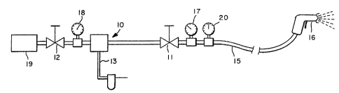
FIG 2 shows a schematic of vortex tube
connected to spray gun 15: The warm air pressure is
vaxied by adjusting warm air control valve ,~1 (which
is normally included as an integral part of the
purchased vortex tube). The warm air temperature is
varied by adjusting cold air pressure valve ~2. Note:
adjustments to either valve can influence the
parameter controlled by the opposite valve and thus
concurrent "'fine tuning' of both valves may be
necessary. Cold aix pressure valve ,~2 is not found on
vortex tubes bought off the shelf and therefore must
be installed by adding pipe fittings to the cold end
of the vortex tube. xt will be apparent to one skilled
in the art how to add such pipe fittings. It may also
be desirable to have a pressure gauge ,~8 before valve
~ and a muffler ,~9 on the cold air exhaust.
.°.VU 9~1/p860() PCT~I~a90~001J1
6
The vortex tube is connected to ;ompressed
air line ,13 which includes air filter ~4 to filter out
possible contaminants such as dirt and oil. The air
in line ~,3 is between 60 - l00 psiy. The warm air side
of the tube is connected with an appropriate flexible
hose ,~"5 to LpHV spray gun ,~ø, It may also be desirable
to install a warm air pressure gauge ,~7 and a warm air
temperature gauge ~0 between valve ,~,~ and spray gun
l0 ~,6. It is also quite possible that future LPHV spray
guns might be designed such that the vortex tube is an
integral part of the gun itself. In addition it is
foreseeable that the warm LPFiV air might be used to
heat the paint prior to atomization. The increased
Z5 Paint temperature lowers the viscosity which could
result in the ability to use higher solids, low VOC .
paint without loss in coating quality. It is also
conceivable that the LPHV' warxa air supply cauld be
used purely as a carrier and shaper of paint spray
20 which has been atomized by other methods (e. y.
electrostatic, ultrasonic, or centrifugal).
One important characteristic of the vortex
tube is the fact that temperature can be readily
controlled to within 2'F. In contrast the temperature
25 variation in the compressed air converter is typically
only wit?ain l0 - 15'F and the temperature with the
turbine method is typically adjustable only by adding
or removing lengths of hose, which is less than
precise.
30 An~ther important advantage which is
obtained by using the vortex tube is that of initial
. cost. Its simplicity and the fact that it can be used
in electrically hazardous areas, as is, makes the cost
of it much less than that equipment used in other
35 methods for supplying warm air to LPHV spray guns. In
addition, the vortex tube method only requires a
°
'7 90108600 ~ ~ P~'I'/US90/U0151
a
utility (compressed air) that is already installed at
sufficient capacity in mast of the companies that are
involved in spray application of coatings.
An experiment was run using a Vortec
328-a5-H vortex tube configured as shown in FIG 2
above. The spray gun utilized was a DeVillbis Model
~'GHV-501. The adjusting valves on the vortex tube were
adjusted so that the warm air supply to the spray gun
was at about 15 psig, about 100°F and 1a-38 SCF°3ri. With
a consistent compressed air supply it was easy to
control the temperature within 2°F once a steady state
was found.
The paint sprayed was DuPont's Imron° 5000
high solids refinish paint. Vz~rious size panels were
hand sprayed from a gun distance of 1,0-12 inches, and
a gun speed of 3-4 feet per second. No problems were
found with gun surface temperature as can be found.
with a turbine system. Some sprayed panels were
ambient cured and others were oven cured. The finished
panels were evaluated visually and were found to be
equal to or better than conventional air atomized
panels in terms of appearance and film build.