Note: Descriptions are shown in the official language in which they were submitted.
~ 3~ J
.
: TITLE OF THE INVENTION
Massag1ng Device
` BACKGROUND OF THE INVEN~ION
~ Thig inv~ntion relates to a massaging devics.
. Massagi~g devices of the type which comprises a handle and at
; least one rolling body serving ~or the rolling massage, rotatably
mounted on a rolling~body axis of ~he handle, in which the rolling-
body axis is arranged in such a way as to be tiltable about a
swivelling spindle e~tending transversely to the principal
direction of extension of the handle, are described, for axample,
in European Patent O 346 942. In the ~nown massaging device, the
swivelling axis o the rolling-body axis extends along the center
line or in the midplane of the handle, between the handle and the
rolling body. Since the rolling-body axis extends in the plane of
the handle or in alignment with the handle, that end of the handle
which is on the rolling-body side is only a short distance from the
surface of the skin during massaging~ As a result, there is the
risk during use of the massaging device that that end of the handle
which is on the swivelling-axis side will rub across the skin,
giving rise to the possibility of in~uries or at least being
unpleasant.
'O A further disadvantage of the known massaging device consists
in the ~act that the rolling body is in a fixed angular position
relative to the handle during massaging. It is therefore
necessary, when rolling in the longitudinal direction over ~urved
parts of the skin, to altar the angular position o the handle to
ensure that the rolling body is in contact over as large an area
(
~ ,j t,~ sJ ~
as possibla. This adaptation to the contours o~ ths s~in requires
considerable skill and attention.
SUMMARY OF THE INVENTION
_
It is an objeat of the invention to further develop a
massaging device of the type stated at the outset in such a way
that it is simple and effective to use, even in the case o~ parts
o~ the body which are highly curved, and does not pose the risk of
injuring the skin.
This ob~ec~ is achieved according to the inventlon by virtue
of the fact that the rolling-body axis is arrangad to the side of
the handle in a fork-shaped part connected swivellably to the
handle by the swivelling spindla, and that the swivelling spindle
extands centrally in the ~ork-shaped part and thus also centrally
in reIation to the rolling body.
By virtue of this design, the rolling body extends parallsl
to the Iongitudinal~axis of the handle instead of in alignment with
it. As a result, lt is at a distance from the handle such that
contact of the handle with the skin during massaging is excluded.
By virtue of the central arrangement of the swi~elling spindle, the
~O rolling body is held in oscillating fashion on the handle. It
therefore adapts during massaging to the contour of~the parts of
the skin to be massaged, even if the angular position of the handle
is constant, thus guaranteeing as good a contact of the rolllng
body as possible. By virtue of the design in accordanae with the
- 2
i.J i,) ~ S3 J
innovation, the massaging device is very particularly suitabl~ for
treating the face since this has a large number of conve~ities and
convacities, ~or axample the eye sockets, the pro~ecting cheek
bones, the nose, the chin and -the lip part. By virtue o the
oscillating suspension of the rolling body, overstressing of
pro;ecting parts of the body is avoided even in the case o~ a
prolonged massage.
The rolling body can be of widely varying design. It
preferably comprises a plurality of individual disks which have
a toothing on their outer curved surface, a~ described ln French
Patent 843,987. Instead of a toothing, the rolling body can also
have needle-shaped points, as shown in German Offenlagungsschrift
3~ 21 750. The worm-like desîgn of the rolling body shown in
German O~fenlegungsschrit 36 10 220 can also be employed in the
present invention.
The deslgn o~ the massaging device is particularly simpl3 in
terms of construction if the fork-shaped part is inserted into a
recess, open towards one side, of the handle and the swivelling
spindle is guided by two side parts of the handle, said side parts
delimiting the recess.
In the massaging device according to ths p~esent invention,
the swivellability of the fork-shaped part can be limited in a
simple manner by stop face~ of the fork-shaped part and contact
faces within the recess.
It has proven particularly advantageous for the handl~ng of
the massaging device if the swivellability of -the ~ork-shaped part
is limited in such a way that in one end position ths rolling body
extends parallel to the handle and in its other end position forms
an acute angle with that end of the handle which is on the rolling~
body side.
For massaging curved par~s of the skin it is advantageous if
two fork-shaped parts each having a rolling body are arranyed in
alignment one behind the other in the handle. If such a massaging
device is, for example, rolled in the longitudinal direction of-the
spinal column, one rolling body tilts to one side and the rolling
body on the other side of the spinal column tilts to the other
side, with the result that both rolling bodies rest a~ainst the
skin over their full length.
The massaging device can optionally be used with a handle
oriented parallel to the axis of the rolling bodies or ~with a
handle oriented transversely to them if the foxk-shaped parts are
arranged in a carrier part and the handle is connected to the
carrier part in such a way as to be swivellable about an axis
~0 extending perpendicularly to the rolling-body axis. As a result,
the massaging device according to the invention can be used from
case to aasa as a massaging device with the overall shape of a
or~, described, for example, in French Patent 843,978~
It contributes to the further lmprovement of the handling of
the massaging device if in addition to being connected to ~he
carrier part in such a way as to be swivellable about the axis
extending perpendicularly to thë rolling-body axes, the handle is
connected to said carrier part in such a way as to be swivellable
about a spindle extending parallel to the xol]ing-body axes.
Massaging devices with rolling bodies arranged one behind the
other are preferxed in certain cases because with them it is
possible to exercise an influence on a larger area of skin than in
the case of a massaging device with only one rolling body or a
plurality of rolling bodies next to one another. The principles
of the invention can also be applied in the case of a so-called
double roller by arranging two rolling bodies one behind the other
in the carrier part.
In addition to the exercising of a mechanical influence on the
skin, the massaging device can also act electrically on the~ skin
if the rolling body is connected to a source of electric current.
The electric current gives rise to a tingling feeling at the
surface of the skin during massaging. The muscles and ner~es are
stimulated thereby.
An increase ln the effect of the massage can also be achieved
by conneoting the rolling body to an electric vibrator.
t ~ ',5 'i~
The massaging device is independent of the curr~nt supply lf
a battery is arranged in the handle for the purposa of supplying
said device with voltage.
The invention admits of numerous embodiments. Two o~ these
are depicted in the attached drawing and are descxibed below.
BRIEF DESCRIPTION OF THE DRAWINGS
Fig. 1 is a side elevational view of a massaging device
according to the invention;
Fig. 2 is a side elevational view in longitudinal section
through the massaging device of Fig. l;
Fig. 3 is a cross-sectional view through the massaging device
along the line III-III in Fig. 2;
Fig. 4 is a side elevational view in, partly in cross-section
through another embodiment of a massaging device according to the
invention;
Fig. 5 ls a plan vlew, partly in cross-section, o the
massaging device aocording to Fig. 5.
-- 6 --
DESCRIPTION OF THE PREFERRED EMBODIMENTS
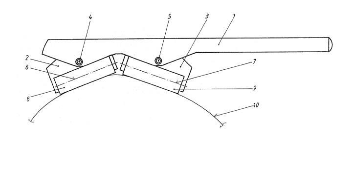
The massaging device depicted in Figure 1 has a handle 1, in
which two fork-shaped parts 2 and 3 are held so as to oscillate
about swivelling spindles 4 and 5, respectively. Fork-shaped parts
2 and 3 support rolling bodies 8 and 9, respectivelyO Each of
rolling bodies 8 and 9 is rotatable about a rolling-body axis 6 or
7. In the position depicted, these rolling bodies 8 and 9 are in
contact with a convexly cuxved skin surface 10. They can be
swivelled about the swivelling spindles 4 and 5 in such a way that
they can move out of the position depicted, via an aligned
position, into an obliqu~ly oriented position.
From Fig~ 2 it can be seen that two recesses 11 and 12 are
present in the handle, each accommodating one fork-shaped part 2
or 3. In~ide the respective recess 11 and 12, each of the fork-
shaped parts 2 and 3 has two stop faces 13 and 14 which abut at an
obtuse angle and, in the ~event of a swivelllng movement o~ the
~ork-shaped parts 2 or 3, are capable of resting against contact
~aces 15 and 16, respectively, formed by the bottom of the reaess
11 or 12. The swivellability of the fork-shaped parts 2 and 3 is
limited thereby.
The rolling bodies 9 are represented in Fig. 2 by individual
sketched disks 17, which can be rotatable about the rolling-body
axis 7 and aan be toothed on their circumferential surface, as
described, for example, in French Patent 843,978.
-- 7 --
Fiy. 3 provides additional clarification of the design o~ the
massaging device. The ~ork-shaped part 3 which is held in the
recess 12 ~o as to oscillate about the swivelling spindle 5 can be
seen. A~ least at the end in which the fork-shap0d parts are
disposed, the handle 1 is hollow, having a top and twa opposed sida
walls, but is open at the bottom. The rolling body 9 rotatable
about the rolling-body axis 7 is also depicte~.
In the embodiment according to Fig. 4, the fork-shap0d part
2 depicted is not held directly in a handle 1, but in a carrier
part 18, so as to oscillate about the swivelling spindle 4. The
handle 1 is connected to this carrier part 18 in such a way as to
be adjustable about a vertical axis 19. In the position
illustrated, a compression spring 20 holds the handle 1 in a
toothing 21 of the carrier part 18. If tha handle l is pulled
upwards relative to the carrier part 18, coun-ter to the force of
the compression spring 20, the toothing 21 disengages~ As a
result, the handle 1 can be rotated by 90 and then locked again
by releasing it. The compression spring 20 then presses it into
the toothing 21 again.
It can furthermore be discerned from Fig. 4 that the handle
1 can, in addition, be swivelled about a spindle 22 extending
transversely to the axis 19. This swivellability is limit~d on
both sides by stop faces 23 and 24, on one side, and 25 and 26, on
the other.
- 8 -
.
The plan view, represented in partial sectlon, in accordancs
with Fig. 5 showg the toothing 21 of the carrier part 1~ by whiGh
the handle 1 can be fixed in the position extending transversely
to the carrier part 18 and in a position in alignment with the
latter. The horizontally extending spindle 22 which makes possibl0
the additional swivellàbility of the handle 1 can also be seen.
-- 9 _