Note: Descriptions are shown in the official language in which they were submitted.
Field of the invent.ion
The invention relates to a process and to an
installation for on-track neutralisation of the rails of
a railway.
Prior art
There has already been proposed a process and a device
for the neutralisation of the new rails of railway tracks
before their laying. This device, such as describsd in
the Patent Applications CH 2350/90 and 2351/90 o~ the
applicant, comprises a heating vehicle provided with
wheals in order to run on the old rails, at least one
heating tunnel which is intended to be traversed by the
new rails during the advance of the vehicle in order to
neutralise them and means for measuring and controlling
the temperature of the new rails.
Summary_of the invention
The object of the present invention consists in
creating a process and an installation for heating which
is suitable, efficient and easy to execute.
For this purpose, the process according to the
: invention is characterised in that:
- at least one heating element is caused to move past
continuously along the rails,
- the value of the temperature of the rails before
their exposure to the heating is measured
continuously,
- the value of the speed of movement past of the
heating elements in relation to the said rails is
measured,
- the value of the change in the temperature of the
rails after heating until the moment of their on-
track fixing is measured,
- the heating of the heating eIements as a function of
the said values is controlled or slaved.
In order to reach a suitable temperature for
neutralisation of the new rails at the place of their
fixing, the procedure i5 preferably characterized in that
the distance between the finish of the heating zone and
the place where the neutralised new rails are fixed on
the track is chosen, for a given speed of movement past
of the heating elements, in such a manner that the
difference in temperature between the surface and the
core of the new rails does not exceed a specified value
and that the temperature of the new rails in the zone of
fixing corresponds, within given tolerances, to the
desired temperature.
The heating of the rails is effected, preferably, by
high-frequency induction, but it may likewise be produced
by electrical resistance or by gas.
The installation according to the invention is
characterized in that it comprises, mounted on a heating
vehicle:
- at least one heating element in the form of an
inductor intended to be traversed by the rail to be
neutralised,
- at least one inverter connected to the inductor in
order to power it at high frequency,
- an apparatus for measuring the speed of movement past
of a rail,
- sensors for measuring the temperature of the rail
before its exposure to the heating and after the heating
in order to measure the change in the cooling until the
place of its fixing,
- an electronic control unit to which are connected the
inverter, the said apparatus and the said sensors, and
- input units for external information and set-point
values, which input units ara likewise connected to the
electronic control unit,
2~$~
Preferred embodlments result from Claims 7 to 9.
Brief descriptio~ of the drawinqs
The invention will be described by means o~ two
embodiments of the clevice for the implementation of the
process for high-frequency heating, by reference to the
attached drawings.
Figure 1 shows a diagrammatic view of a heating
vehicle supplied with two high~frequency heating tunnels
permitting the implementation of the process according to
the invention.
Figure 2 is an enlarged sectional view of the tunnels
alone.
Figure 3 is the block diagram for control of an
installation for the high-frequency induction heating
according to the invention.
Figures 4 and 5 show a second embodiment of a heating
vehicle followed by an assembly vehicle for the fixing of
the neutralised new rails.
Figures 4a and 5a are plan views of the track in order
to illustrate the positions of the old rails R1 and of
the new rails R2 and their lateral displacement during
the substitution, as well as some components of the
vehicles.
Figures 6 and 7 are enlarged sectional views of the
tunnels of Figure 4 according to two diffrent variants.
Figure 8 is the block diagram for control of an
installation for the heating, which installation is
adapted for the device according to Figures 4 and 5.
Description of the preferred embodiments
By reference to Figures 1 and 2, there is first
described briefly the example of a vehicle 1 on which is
installed the heating device incorporated in the heating
tunnels 5, 5'. The vehicle 1 is designed to run on the
2 ~ 3 ~ ~
old track R1, in the direction of the arrow, in order to
raise the new rails R2, which have been previously
deposited along the railway track, and to neutralise them
by heating immediately before their laying and,
simultaneously, to detach the old rails R1 from the
track. The progress of the operations is effected such as
is described in the Patent Application CH 2350/90 of the
applicant. Behind the vehicle 1, not shown in Figure 1,
the released old rails R1 are removed from the track and
the new rails R2 are laid, as is described in the Patent
10 Application CH 2351/90 of the applicant and in the
example according to Figures 4 and 5.
Vehicle 1 comprises a body Z supported by a leading
bogie 3 with two axles 3a and by a rear bogie 4 likewise
with two axles 4a. Between these axles 3a, 4a are
installed the two heating tunnels 5, 5', one for each
stretch o~ new rails R2 (Yigure 2).
As illustrated in Figure 2, these two tunnels 5, 5'
are mounted in common holders 6 disposed above the centre
of the track and suspended beneath the body 2. They are
fo~med by two lateral walls 6a separated by a common
central wall 6b. The three walls of the holder join
together at their upper portion and, at specified
intervals, are extended by mountings 6c suspended from
the body 2, such that the positioning of the tunnels is
centred in relation to the body 2 and consequently in
relation to the track. The heating of the rails R2 to be
neutralised is produced by high-frequency induction: For
this purpose, the rails R2 pass on the inside of
inductors in the form of one-turn coils 12, which coils
are connected to inverters, and are displaced on guide
rollers 7 fixed in the walls 6a, 6b of the tunnels 5, 5'
between the inductors.
The disposition of these tunnels 5, 5' is such that
the path of the rails RZ to be neutralised is located
below the axles 3a, 4a, at a distance of between 20 to 40
cm, preferably between 25 and 30 cm, from the ballast. By
virtue of this disposition, there is no need to lift the
rails very high and especially above the axles, which
facilitates the work and the guiding of the rails.
On either side of the tunnels 5, 5' are provided work
stations in retractable platforms 9, 10 suspended from
the body 2 of the vehicle by jacks 9a, 10a and on which
are located automatic or manual detaching units, for
example automatic sleeper-screw drivers 9b, 10b and
movable seats 9c, 10c for the workers who remove the
fastenings or release the fixtures of the old rails to
the sleepers.
At the front of the vehicle 1 are installed means 8
for gripping the new rails R2, which have been previously
disposed in the centre of the track or on either side of
the track. These gripping means 8 make it possible to
catch and to introduce these rails R2 into the heating
tunnels 5, 5'.
At the rear of the vehicle 1 are provided rail lifters
11 which catch the heated new rails R2 at the exit of the
tunnels 5, 5' and guide them on to the track where, after
the old rails R1 have been removed, they will be laid and
then fixed on the sleepers by known means.
By reference to Figure 3, there will now be described
the block diagram of the installation for the
implementation of the process for on-track neutralisation
of the rails of a railway, by high-frequency induction.
This heating installation, mounted on the heating
vehicla 1, comprises a heating zone formed by several
inductors distributed in each tunnel 5, 5'. In th~
example considered there are three inductors 12, 13, 14,
disposed one after tha other, which are formed, in a
manner known per se, by a one-turn coil produced as a
hollow tube of copper, each one of a length of 1 mO These
are modules of inductors of a similar construction, which
are prefabricated, and this makes it possible to compose
heating zones of desired length by varying the number of
these modules according to need.
By utilising only three inductors of a length of 3 m,
it is evident that the tunnels 5, 5' may be shorter than
as indicated in Figure 1.
The inductors 12, 13, 14 are powered by two inverters
15, 16 with a power of 100 kW and 200 kW respectively and
of 1000 Hz. The inductor 12 is connected to the 100 kW
inverter 15 and the inductors 13, 14 are connected to the
200 kW inverter 16, and this makes it possible to give
flexibility to the adjustment of the temperature. There
is further provided a refrigerator set, not shown, in
order to ensure the cooling of the inductors by
circulation of cold water through the hollow turns, in a
closed circuit, without a continuous inflow of water from
outside the convoy.
Of course, there is provided a heating~installation
with three modules of inductors in each one of the
tunnels 5, 5' as are illustrated in Figures 1 and 2 and
which are trav~rsed as described hereinabove by each
stretch of new rails R2.
The inverters 15, 16 are connected to an electronic
control unit 17. In front of the inductors 12, 13, 14 are
installed in each tunnel 5, 5' apparatuses 18 for
measuring the speed of movement past of the rails R2 in
relation to the vehicle 1 and sensors 19 for measuring
the temperature of the rails before their exposure to the
heating. In Figure 3 there is indicated at a distance L
from the finish of the heating zone, therefore at the
rear end of the inductor 14, the zone ZF for fixing the
new rails R2~ Within this distance L are installed, at
regular intervals, a plurality of sensors 20 for
measuring the temperature of the rails J which sensors
sense the slow cooling of the ra:il which occurs.
Generally the rear end of the last inductor 14 coincides
with the rear end of the tunnel 5, 5'.
The electronic control unit 17 to which are connected
the outputs of the units 18, 19, 20, thus receives all
the information on the conditions of the speed and of the
temperature of the rails R2. Furthermore, this unit 17
also receives external information from an input unit 21
and set-point values from an input unit 22 via an
operator control interface 23 adapted to the operational
staff. The external informat:;on comprises all the
essential external factors, namely the profile of the
rails, the type of steel from which the rails are
produced, the external temperature and, if necessary,
other factors which could have an influence on the
cooling speed of the rails (rain, wind, and so on).
To this unit 17 are likewise connected, as outpu~
units, a device for printing protocols 24 and an optical
unit 25 for visualisation of the temperature profile and
of the state of the process.
The electronic control unit 17 comprises the
processing of the temperature measurements, the
adjustment of the heating units, thP management and the
control of the process as a function of the v~lues of the
temperature of the rails before their exposure to the
heating, of the speed of movement past of the heating
elements in relation to the rails, and of the value of
the change in the temperature of the rails after heating
until the moment of their on-track fixing.
In order to reach a uniform heating of the total mass
of the rails throughout their section, it is necessary,
after the heating, to wait a certain time in ordsr that
the temperature during the cooling phase becomes equal
throughout the total mass of the rail. For this reason,
the distance L is important and will be chosen in such a
20~9~:~
manner that, for a given speed of movement past of the
heating elements, the difference in temperature between
the surface and the core of the new rails does not exceed
a specified value and the temperature of the new rails in
the zone of fixing ZF corresponds, with given tolerances,
to the desired temperature.
Generally, the temperature of neutralisation during
the fixing must be 25C ~ 0.5C. Concerning the
equalisation of the temperature, it has been established
that, for example for a speed of movement past of 6 m per
minute, and for lengths respecl-ively of L=8 m, L=10.5 m,
L=17 m and L=21 m, the difference in temperature between
the surface and the core of the rail, expressed as a
percentage dsviation, increases respectively to 8, 6, 4
and 3%. Thus if there is chosen an absolute deviation in
the difference of the surface/core temperature of 4% at
25C, therefore + 1C, it is necessary to choose a length
L=17 m, which corresponds to a speed of movement past of
6 m/mn in a time of 170 s. Therefore, tXe distance L
depends principally on the admissible deviation in
temperature between the surface and the core and the
speed of displacement.
Figures 4 and 5 show, as a preferred example, a second
embodiment of a heating vehicle 1 having shorter heating
tunnels 5a, ~b, followed by a vehicle 2 for assembly of
the new rails.
The parts of the heating vehicle 1 which correspond to
the parts of the first example have the same reference
symbols. In this case, the heating tunnels are shorter.
Vehicle 1 (Figure 4) supplied with a leading bogie 3
and with a rear bogie 4 runs on the old rails R1 and
comprises a body 2 comprising a cabin 2a, compartments 2b
for inverters which supply power at high frequency to the
inductors of each heating tunnel, compartments 2c for the
refrigerator sets which cool the inductors, a tank 2d for
2 ~
the fuel oil, generator sets 2e, that supply power to the
inverters, and sets of capacitors 2f, associated with the
inductors. The new rails R2, previously deposited in the
middle of the track, are caught at the front of the
vehicle 1 by gripping means 8 and laid onto the guide
rollers 28, which are fix~d on the framework of the
vehicle and distributed along the latter, in such a
manner that the new rails R2 can pass beneath the axles
3a, 4a and between the wheels oE the bogies 3 and 4.
The heating tunnels are installed in the zone of the
rear end of the vehicle 1 in the middle of the track, in
a commun holder (Figure 6). For the case considered they
are divided into two parts 5a, 5b fixed to the framework
29, one situated before and the other after the rear
bogie 4. The part 5a comprises two inductor units each
having a length of 1 m, and therefore has a length of
only 2 m, while the part 5b comprises only one inductor
which is 1 m in length. Each inductor 12 has the form of
a one-turn coil and is connected to a set of capacitors;
the oscillating circuit formed by this coil and said
capacitors is fed by the inverters. By virtue of the
short length of the tunnel, the rails R2 are not required
to be guided in the interior of the tunnel, but may pass
through it freely. Of course, each part of the tunnel
comprises two sections which are placed side by side, one
for each stretch of rails, as shown in Figure 6 for the
parts 5a, 5a', which sections are provided with inductor~
12 surrounding the two rails R2. In order to ensure a
correct centred guiding, each part of the tunnels may be
supplied with rollers 7a which bear on and run on the
rails R2 passing this part, these rollers being installed
before and after the inductors, respectively between the
inductors. The parts of the tunnels are suspended from
the framework 29 in such a manner that they are slightly
movable in relation to the framework in order to allow
them self-adjustment.
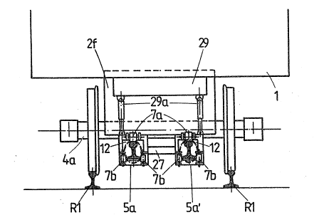
According to the variant of Figure 7, the two sections
5a, Sa' of the tunnel provided for each stretch of rail
are spaced, connected by a traverse 27 and suspended from
the framework 29 by means of jacks 29a which permit to
lift them when the vehicle is running light. Each tunnel
is provided not only with rollers 7a bearing on the rails
R2 but also with rollers 7b on both sides of each rail
for the lateral guiding.
In order to detach the old rails R1, there are
provided detaching units on two platforms 9, 10 which are
suspended from a framework 29; these platforms are
equipped with tools for disassembling the fixtures, such
as automatic sleeper-screw drivers 9b, lOb, and are
supplied with wheels 9d, lOd in order to run on the rails
Rl.
At the rear, the vehicle 1 comprises rail-guides 33
for the old rails Rl that are released, a cantilevered
frame 30 carrying an adjustable support 31 provided with
rail lifters 31a which lift the rails Rl (Figure 4) and
~20 move them apart (Figure 4a), as well as a tracked
conveyor 32 running on the sleepers in order to prevent
them from leaving the ballast during the lifting of the
rails R1~ ~he frame 30 may be displaced towards the
interior of the vehicle by virtue of the rollers 30a
running on slide bars on the framework 2g.
The assembly vehicle 40 (Figure 5), having the bogies
35 and 36, runs on the new rails R2 which are laid in
their correct position on the sleepers ahead of the bogie
35. For this purpose, the vehicle comprises, at the
front, a cantilevered frame 37 supplied with an adjust-
able support 38 carrying rail lifters 39 for moving the
rails R2 apart towards the fixing positions, as Figure 5a
shows. The frame 37 may be displaced towards the interior
of the vehicle by virtue of the rollers 37a running on
slide bars of the framework 40a.
Below the framework 40a of the vehicle 40 are mounted
an auxiliary heating tunnel 5c, which is positioned in
front of the vehicle and covering the rails R2 from the
top, and other rail lifters 39a for the positioning of
these rails R2 on the sleepers T. This auxiliary tunnel
5c comes into opera~ion only after an interruption in the
work for reheating the rails R2 that have already left
the tunnel 5a, 5b before their fixing.
A connection 41 between the vehicles 1 and 40
comprising an electrical line and a cooling duct serves
to power this part 5c of the tunnel.
Vehicle 40 comprises moreover cabins at the front 42
and the rear 43, a generator set 44 and assembly stations
on the two platforms 45. These platforms are suspended
from the framework 40a and are supplied wiih tools ~or
the assembly of the fixtures, especially automatic
sleeper-screw drivers 46, as well as wheels 45a to run on
the rails R2. The old rails Rl are guided by guide
rollers 47 and are depcsited by the side of the track as
~20 Figure 5a shows.
At the rear of the vehicle 40 are provided means 48
for ~ollecting the fastenings disassembled by the
detaching units of the vehicle 1 and deposited on the
track. These fastenings are transported by conveyors 48a
to storage places 49 and by conveyors 50 to the fastening
units on the platforms 45~
Figure 8 shows the block diagram of the installation
intended for the vehicles 1 and 40 according to Figures 4
and 5 and is very similar to that illustrated in Figure
3. The same units are designated by the same re~erence
symbols and will not be described again. The
modifications in relation to Figure 3 are the following:
An inverter 15a, of 50 kW rms power, supplies the two
inductors 12, 13 mounted in each part 5a of the tunnels,
and an inverter 16a, of 100 kW rms power, supplies the
inductor 14 mounted in each part 5b of the tunnels or
else an auxiliary inductor 26 mounted in each part 5c of
the tunnels at the front of the vehicle 40. An inverter
27 permits the connection of the inverter 16a to the
inductor 14 or 26. In this case the inverters work at 2
kHz. Each inductor, designed as a module, is formed by a
hollow one-turn coil and its length is 1 m.
Of course, the process according to the invention may
be implemented by installations other than those which
have just been described, in particular the source of
heat could be different. High-frequency induction
heating, which is the preferred heating, could especially
be replaced by electrical resistance heating or by
heating with gas.