Note: Descriptions are shown in the official language in which they were submitted.
2~4~6~ -
47273-3
~rUADRA~T LOG F~ED~R
The present inven~ion relates to an apparatus for
sorting and separating logs so they may be fed individually
for further processing. More particularlyr the present
invention provides a quadrant log feeder that separates logs
of many different sizes and shapes and feeds the logs one at
a time for further processing.
Logs received in a sawmill vary in diameter and length.
Some logs are straight, and others are far from straight and
have a variety of physical shapes and deformities including
taper, flared butts, hooks, crooks, branch stubs, branches,
cat ~aces, splits, and loose-bark. In some cases groups of
logs are moved on a transverse conveyor sometimes one on top
of the other or crossed and tangled in a way that makss them
difficult to separate by normal means. Thus, a log sorter
is provided 80 that the logs can be separated and regrouped
into smaller groups or moved one at a time on an exit
conveyor for grading and subsequent processing.
There are different types of log sorters. Rotary log
sorters have drums that rotate with pockets or arms. Most
of these rotate continuously and this continuous rotation
can present a problem if crossed logs or curved logs are
caught in a drum. Examples of such a sorter are U.S.
Patents 4,852,716 to Roche, and 5,011,024 to Bunney. Other
types of log sorters include those which have discs or arms
that pick up a log at several positions along its length.
Such sorters sometimes have a crooked log or branch caught ~ ~ -
between the discs and jam-ups can occur in the sorting
30 operation. Step sorters are also available which sort logs ~ -
in a series of steps. One example of a step sorter is
Canadian Patent 692,593 to Nienstedt. Other patents that ~ ~ -
relate to different types of sorters or singulators are U.S.
Patents 4,245t735; 4,624,361; 4,911,283 and 4,930,616.
~$ ' ' '
: .: :.....
2046q6~
It is an aim of the present invention to provide a
log feeder that has a ~yclic motion to assist in
realigning logs, particularly those that are crossed and
are caught up with other logs. Furthermore, it is
another aim of the invention to provide a log feeder that
can handle logs with a large variation in diameter and
logs that are both straight, tapered and crooked.
It is a still further aim of the present invention
to provide a log feeder that is adaptable to a fully
automatic system and has continuous surfaces across the
face to prevent logs or branche~ being jammed in the
apparatus. Furthermore, by providing an apparatus with
no aperture~ or holes in the face of the feeder, refuse
does not collect under the apparatus.
It i8 a further aim of the present invention to
provide a log feeder which i~ less costly and takes up
le~s space than existing log feeder~. The feeder of the
present invention handles long log lengths and short
lengths, and is adaptable for multiple use wherein two or
more log feeders can be placed in series with the exit
from the first feeder leading to the entrance to the
second feeder. Furthermore the output from the log
feeder is provided at a higher elevation than a
transverse input conveyor which can have advantages in a
mill operation. This difference in elevation can be
adjusted depending upon the requirements in a mill.
The present invention provides an apparatus for
separating logs of varying sizes and feeding logs
individually, comprising:
a first holding location for receiving logs;
a movable member having a surface to ~upport at ~-
least one log;
,
D ~ ~
.~ .
- 2a~046q6 1
means to move the movable member from an entry
position adjacent the first holding location, adapted to
accept at least one log rom the fi~st holding location,
upwards to an exit posit.ion where a log leaves the top
edge and moves to a second holding location; and
a fixed surface in the path of the movable member
that acts to eject logs from the surface of the movable
member of the movable member as the member moves past the
10 fixed ~urface to retain a single log on th~ surface o -- .
the movable member for delivery to the second holding
location.
The present invention provides an apparatus for
separating logs of varying sizes and feeding logs
15 individually, comprising: a first holding location for
receiving logs; a movable quadrant having a shelf at a
top edge to support at least one log, the movable
quadrant having a curved peripheral surface; means to
rotate the movable quadrant from an entry position
20 adjacent the first holding location, adapted to accept at
least one log from the first holding location, upwards to
an exit position .: .
:
, .
.::
.~.-,.
,
,:',' ' ~
D ~ ~ -
.~.. .
:. :,-:::
~ 3 - 20~9~1
where a log leaves the shelf and moves to a second holding
location; a fixed quadrant coaxial with and having a smaller
radius than the movable quadrant, the fixed quadrant having
a curved peripheral surface and positioned so the movable
quadrant rotates and covers the fixed quadrant when moving
from the entry position to the exit position; radial fins
extending from the surface of the fixed quadrant having an
increasing radius from bottom to top of thle surface of the
fixed quadrant; slots in the shelf of the movable quadrant
for the radial fins to pass therethrough and retain one log
on the shelf when the movable quadrant rotates to the exit
position; in line rotatable discs having aligned notches
therein, positioned adjacent the second holding location to
receive a log in the notches, and means to rotate the discs
to transfer a log from within the notches in the discs to an
exit.
In drawings which illustrate embodiments of the present
invention:
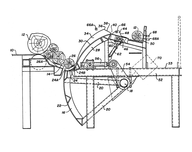
Figure 1 is a schematic side elevational view showing
an apparatus for separating logs according to one embodiment
of the present invention with the movable quadrant in the
entry position.
Figure 2 is a schematic side elevational view as ~hown
in Figure 1 with the movable quadrant in the exit position.
Figure 3 is a schematic isometric view of the apparatus
shown in Figures 1 and 2.
. .
Referring now to the drawings a transverse entry chain
conveyor I0 is shown conveying a plurality of logs 12 having ~ -
different diameters to form a dam in a first holding
location 14 which is just below the elevation of the
transverse conveyor 10. A movable quadrant 16 is pivoted
about an axial shaft 18 having two arms 20 supporting the
quadrant 16. The arms are provided at both ends of the
2~4~961
-- 4 --
quadrant. The quadrant 16 has a continuous curved plate 22
with no holes or apertures therein to allow debris or logs
to pro~ect through the quadrant to cause a jam. At the top
of the quadrant 16 is a shelf 24 extending for the full
length of the quadrant 16. The shelf 24 is in the form of a
hook having a short portion 24A adjacent the outside surf~ce
of the quadrant 16 being substantially horizontal, and the
longer portion 24B being ~loped upwards. The purpoie of the
shelf 24 will be explained hereafter.
Figure 1 illustrates the quadrant 16 shown in what is
referred to as the entry position so that logs from the
first holding location 14 fall onto the shelf 24D Initially
one or more logs may fall onto the shelf 24~ If a dam of
logs builds up so that it crosses lines from optical
detectors 26 and 26A, such as photoelectric cells, then the
transverse conveyor 10 stops.
A fixed quadrant 28 coaxial with the movable quadrant
16 is positioned above the movable quadrant 16 and has a
smaller radius than the movable quadrant 16. The fixed
20 quadrant 28 has a peripheral curved surface plate 30 which ~ -
extends from end to end of the quadrant 28. Slots 32 shown
more clearly in Figure 3 are provided towards the ends of
the fixed quadrant 28 for the arms 20 of the movable
quadrant to pass therethrough.
A plurality of radial ribs 3~ shown more clearly in
Figure 3, extend up from the surface plate 30 of the fixed
quadrant 28. The radial ribs 34 are shown at the base to
have substantially the same slope as the shelf 24, reduce in
radius and then 510wly increase up the ~ixed quadrant 28 to -
a top peak 36 followed by end sloped portions 38 downwards
to a second holding location 40. As shown in Figure 3,
slots 42 are provided in the shelf 24 for the ribs 34 to
pass through when the movable ~juadrant 16 moves to the exit
position. ~-
.- ' ' .
.
: ' '
5 2046~61
Figure 2 illustrates the movable quadrant 16 moved
from an entry position as shown in Figure 1 to an exit
position so that the shelf 24 terminates being
substantially parallel to the end sloped portions 38 of
5 the ribs 34. The movable quadrant can be rotated through
an angle in the range of about 45 to 70 when moved
between the two end position.
A series of rotating discs 44 mounted on rotating
shaft 46 are positioned beside the second holding
10 location 40 and have notches 48 aligned up in ea~h disc
positioned as shown in Figure 2 so that log 12 rests in
the notches 48 when in the second holding location 40.
The discs 44 rotate to an exit position as shown in
Figure 1 and the log 10 rolls down onto an exit conveyor
15 50 which moves a single log away.
The apparatus is mounted on a frame 52 having a
walkway 53 adjacent the exit conveyor 50~ As seen, the
exit conveyor 50 is higher than the transverse conveyor 1 -- -~
so that the departing log is at a higher elevation than
20 the logs entering the separator. The shaft 18 supporting
the movable quadrant 16 has an arm 54 keyed thereto and a
pneumatic or hydraulic cylinder 56 is attached to the end
of the arm 54 and when in the extended position as shown
in Figure 2, moves the quadrant 16 to the exit position
25 and when in the retracted position as shown in Figure 1,
moves the quadrant to the entry position. One cylinder
56 only is generally sufficient to move the quadrant 16. --
:' :
The discs 44 have an offset arm 60 with a cylinder
62 attached thereto. The cylinder may be hydraulic or
pneumatic and when extended i3 shown in the position of
~igure 2 to receive a log in the second holding location
4 and when retracted rotates the log 12 to allow it to
roll or slide onto the output conveyor 50.
.~'
J ; ~
.,~ .: .
,, . .. , . , . - .. .~ - . . . - . , .
5a 2 04 6q 6l
A5 shown in Figure 1, optical detectoxs 66 and 66A
are positioned at the second holding location 40 and
abov0 the fins 34 close to the top peak 36 to ensure that
the movable quadrant 16 does not move upwa:rds until a log
or logs in the second holding location 40 has been moved.
Furthermore,
..
' " '-"' ~
' '..' :':
~: . . '. -
~: ~ ' ,,
20~9~
another photoelectric cell 68 is positioned over the output
conveyor 50 to ensure that the discs 44 are not rotated when
there is still an existing log or logs on the conveyor 50.
In operation, the photoelectric cell 66 indicates there
is no log positioned in the second holding location 40,
therefore, the cylinder 56 commences to move the quadrant 16
up from the entry position. One or more logs may rest on
the shelf 24 and as the quadrant moves up, the ribs 34 pass
through the slots 42 in the shelf 24. The log 34 slowly
rotates on the ribs which also push the log out as the shelf
moves out. Although the useful width cf the shelf 4 is
reduced because the ribs 32 increase in radius, the centre
of gravity of the log changes as it moves up the circular
path, and thus prevents the log from falling off the shelf
24 while sorting other logs and allowing them to fall back
into the first holding location 140 If there are several
logs on the shelf all but one log or one small group of logs
fall back into the first holding location 14. Furthermore,
if logs are crossed or crooked, they too tend to rotate on ~.
the ribs 34 and are pushed outwards as the width of the
shelf is reduced by the ribs 34. Thus when the shelf 24 .
reaches the exit position, only one log 12 or one single : .
layex of logs remain on the shelf and it rolls down the
sloped portions 38 of the ribs 34 into the second holding
location 40, as shown in Figure 2. The discs 44 then
rotate, the log 12 is held in the notches 48 of the discs 44
and the log is deposited to roll or slide down onto the
output conveyor 50 for conveyance away from the separator. :
As the movable quadrant 16 moves up, the continuous
curved plate 22 contains logs in the dam of the first
holding locati~n 14. The logs 12 may rotate, particularly :
if the log has a rough surface and this tends to untangle
logs. Debris does not fall into the quadrant mechanism as
there are no apertures or holes in the plate 22
, .
~ Q
2~9~1
The equipment utilizes the centre of gravity of the
largest logs that may occur for placements of combinations
of smaller logs to produce a profile for the top of the
movable quadrant 16 adjacent to the fixed quadrant 28 so
that only one log o~ larger diameter or small groups of logs
of smaller diameters are elevated by the shelf 24.
Whereas one separator is shown herein, a second
separator may be mounted so that the first holding location
14 for the second separator replaces the output conveyor 50
on the first separator and raises the logs to a higher
elevation while contributing to further ssparation. This is
particularly applicable for a large range of diameters. -
Furthermore, it raises the elevation of the output conveyor
50 which is desirable in certain mills~ The dimensions of
the separators may be changed to suit the sizes of logs to
be handled and the separation requirements.
When the movable quadrant 16 returns to the entry ~
position, the curved plate 22 of the movable quadrant 16 ~ -
does not allow logs already in the first holding location 14
to jam. As soon as the shelf 24 has returned to the entry
position, another log moves onto the shelf 24.
In another embodiment a counter weight 70, as shown in ~-
dotted line in Figure 1, is provided on an extension of arm
or arms 20 reduces the force necessary to move the quadrant -
16. A double acting cylinder 56 i~ provided so pressure may
be provided on both sides of a piston to both raise and
lower the quadrant and rectify a portion of the live load.
Whereas a counter weight 70 is shown herein this may be - -
replaced by a spring, air bag or other suitable mechanisms.
Various changes may be made to the embodiments shown
herein without departing from the scope of the present
invention which is limited only by the ~ollowing claims.
. . .
-
' ": '