Note: Descriptions are shown in the official language in which they were submitted.
2046974
1 62948-151
ENDOVASCULAR GRAFTING APPARATUS, SYSTEM AND METHOD
AND DEVICES FOR USE THEREWITH
This invention relates to endovascular grafting
apparatus, system and method and devices for use therewith.
The state of the art is described in the background of
the invention in Patent No. 4,787,899.
In general, it is an object of the present invention to
provide an endovascular grafting apparatus, system and method and
devices for use therewith which overcome the disadvantages of the
prior art apparatus, systems and devices.
Another object of the invention is to provide an
apparatus and system of the above character which utilizes a
pusher rod assembly which is constrained so that relatively great
forces can be applied by the pusher rod assembly.
Another object of the invention is to provide an
apparatus and system of the above character in which the capsule
is flexible so that it can negotiate bends in the vessels of a
patient.
Another object of the invention is to provide a grafting
apparatus and system which utilizes a flexible capsule which can
contain a graft with hook-like elements without any danger of the
hook-like elements penetrating the capsule.
Another object of the invention is to provide an
apparatus and system of the above character in which the graft
automatically springs into an open or expanded position when it is
released from the capsule.
Another object of the invention is to provide an
apparatus, system and method of the above character in which a
- ~,
2046974
2 62948-151
pushing force is applied to the distal extremity of the balloon
for advancing a graft out of the capsule.
Another object of the invention is to provide an
apparatus and system of the above character in which a fixed wire
or an over-the-wire guide wire system can be used.
Another object of the invention is to provide an
apparatus and system of the above character in which the graft can
be compressed to a very small size in a flexible capsule.
According to a broad aspect of the invention there is
0 provided an endovascular grafting system, comprising:
a capsule catheter comprising a flexible elongate tubular
member having proximal and distal extremities, and a capsule
mounted on the distal extremity of the elongate tubular member,
the capsule being substantially cylindrical in shape and having an
inner wall, the capsule being formed of a helical wrap of a metal
ribbon and means bonding the helical wrap into a unitary capsule
while permitting bending of the capsule;
a graft disposed within the capsule, said graft comprising a
tubular member having proximal and distal ends, hook-like
attachment means secured to the proximal and distal ends of the
tubular member of said graft, the attachment means facing in a
direction outwardly towards the inner wall of the capsule; and
push rod means disposed within said capsule catheter and
engaging said graft, wherein, upon relative movement between said
push rod means and said capsule catheter, said graft can be forced
out of the capsule.
According to another broad aspect of the invention there
is provided a catheter assembly comprising a prosthesis, and a
A
2046974
2a 62948-151
flexible elongate tubular member having proximal and distal ends,
the improvement comprising:
a retaining means for retaining said prosthesis in an
unexpanded state, said retaining means being mounted on said
distal end of said tubular member and being substantially
cylindrical in shape and being formed of helical wraps of a metal
ribbon; and
a means for bonding said helical wraps so that said retaining
means is flexible along its longitudinal axis.
According to another broad aspect of the invention there
is provided a system for implanting a prosthesis in a vessel
having a wall, said system comprising:
graft means for repairing the vessel, said graft means
including a tubular graft having proximal and distal ends, and
attachment means for engaging the vessel wall, the attachment
means being secured to the proximal and distal ends of the tubular
graft;
first catheter means for advancing said graft means in the
vessel, said catheter means including a first elongate tubular
member having proximal and distal ends, and capsule means for
removably receiving said graft means, the capsule means being
secured to the distal end of the first elongate tubular member and
being formed of a helical wrap of metal ribbon; and
second catheter means for implanting said graft means, said
second catheter means being disposed within said first catheter
means, wherein, upon relative movement between said first catheter
means and said second catheter means, said graft means is
removable from the capsule means.
2046974
2b 62948-151
Additional objects and features of the invention will
appear in the following description in conjunction with the
accompanying drawings.
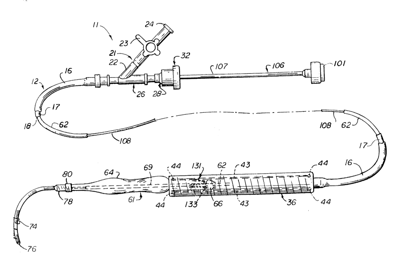
Figure 1 is an isometric view of an endovascular
grafting apparatus and system incorporating the present invention.
Figure 2 is a side elevational view partially in cross
section of a capsule catheter incorporating the present invention.
6974
-3-
Figure 3 is a side elevational view partially in cross
section showing a balloon catheter assembly
incorporating the present invention.
Figure 4 is a partial side elevational view in cross
section of a portion of an alternative balloon catheter
assembly incorporatingthe present invention showingthe
use of a movable pusher button capable of sliding over
a limited range.
Figure 5 is a side elevational view partially in cross
section of another alternative embodiment of a balloon
catheter assembly incorporating the present invention
showing the use of a movable guide wire.
Figure 6 is a cross sectional view taken along the line
6-6 of Figure 5.
Figure 7 is a side elevational view partially in cross
section of a pusher rod assembly incorporating the
present invention.
Figure 8 is a side elevational view partially in cross
section of another embodiment of a pusher rod assembly
incorporating the present invention.
Figure 9 is a cross 6ectional view partially in cross
section showing in combination a balloon catheter and
a pusher rod assembly and a movable guide wire.
Figure 10 is a side elevational view of a graft
incorporating the present invention.
Figure 11 is an enlarged isometric view showing one of
the spring attachment means utilized on the graft.
A-53261/HCH
20~6974
-4-
Figure 12 is a partial enlarged view of an alternative
hook-like element utilized in the spring attachment
means of Figure 11.
Figure 13 is an enlarged view showing another embodiment
of a hook-like element used in the spring attachment
means of Figure 11.
Figure 14 is a side elevational view partially in cross
section showing the manner in which the graft is held
in the capsule after ejection of the proximal extremity
of the graft from the capsule.
Figure 15 is a view similar to Figure 14 but showing the
proximal and distal extremities of the graft outside of
the capsule with the balloon retracted so that it is
within the graft and inflated to force the distal
attachment means into the vessel wall.
In general, the endovascular grafting system is
comprised of a capsule catheter having a flexible
elongate tubular member with proximal and distal
extremities and a capsule mounted on the distal
extremity of the tubular member. The capsule is
generally cylindrical in shape and is formed of a
helical wrap of a metal ribbon. Means is provided for
bonding said wraps into a unitary capsule while
permitting bending of said unitary capsule. A graft is
disposed within the capsule. The graft is comprised of
a tubular member having proximal and distal ends. Hook-
like attachment means is secured to the proximal and
distal ends of the tubular member and face in a
direction outwardly towards the inner wall of the
capsule. Push rod means is disposed within the capsule
catheter and engages the graft whereby upon relative
A-53261/HCH
-s- 2046974
movement between the push rod means and the capsule
catheter, the graft can be forced out of the cap~ule.
More in particular, the endovascular grafting apparatus
and system 11 and the devices for use therein are shown
in Figures 1-10. This apparatus and system 11 includes
a capsule catheter 12 (see Figure 2) which consists of
a flexible elongate tubular member 16 formed Qf a
suitable plastic material such as Nylon of a sui~able
length as, for example, 40 to 100 centimeters and
preferably approximately 43 centimeters for the
abdominal aortic artery and approximately 70 centimeters
for the thoracic aortic artery. The tubular member 16
can have a suitable size such as an outside diameter of
.187 inches and an inside diameter of .125 inches. The
tubular member 16 can be produced in a certain color
such as blue. In order to make it radiopaque under x-
rays, the flexible tubular member 16 i6 loaded wlth a
suitable radiopaque material such as bismuth
subcarbonate or barium sulfate. By way of example, the
flexible elongate member 16 can be compounded with
approximately 20% of the radiopaque material by weight.
An inner liner 17 is provided which is mounted within
the tubular member 16. The liner 17 i6 sized so that
it will fit within the tubular member 16. The liner is
preferably formed of a lubricious material ~uch as
Tefzel (ethylene tetrafluoroethylene) or Teflo~ FEP
(flourinated ethylene polypropylene). It can have an
inside diameter of .085 inches and an outside diameter
of .125 inches and a length as, for example, 41
centimeters which is slightly less than that of the
tubular member 16. If desired, the inside diameter of
the liner 17 can be in the range of .075 to .120 inches.
The liner 17 is provided with a lumen 18 which extends
~trade-mark
62948-151
2046974
--6--
the length thereof. The liner 17 reduces the inside
diameter of the lumen 18 for a purpose hereinafter
described. The liner 17 is made of a radiation stable
material so that the catheter can be radiation
sterilized. Tefzel, or Teflon FEP, which is a polymer
is such a radiation sterilizable material. The inner
liner 17 also serves to provide additional columnar
strength to the catheter 12.
A wye adapter 21 is secured to the proximal extremity
of the flexible tubular member 16. The side arm 22 of
the adapter 21 has a stop cock 23 mounted therein which
is movable between open and closed positions. The stop
cock 23 is provided with a Luer fitting 24 which is
adapted to be secured to a syringe which can be utilized
for injecting a dye, or medications such as a vaso-
dilator. The central arm 26 of the adapter 21 is
connected to a Touhy Borst adapter 27 and includes a
female part 28 that carries an O-ring 29 which is
adapted to be engaged by a protrusion 31 forming a part
of the male part 32.
The capsule catheter 12 has a capsule 36 incorporating
the present invention mounted on the distal extremity
of the flexible elongate tubular member 16. The capsule
36 when used in humans has a diameter ranging from 4 to
8 millimeters. The flexible elongate tubular member 16
which also serves as a shaft for advancing the capsule
36 as hereinafter described and should have a diameter
which is less than that of the capsule and therefore has
an outside diameter ranging from 3 to 7 millimeters.
The capsule 36 is a composite structure and is formed
of an inner layer 37 and an outer layer 38. The inner
layer 37 is formed of a stainless steel ribbon 39 with
A-53261/HCH
7 2(~ ~6974
the ribbon having a width of .150 inches and a thickness
ranging from .002 to .004 inches and preferably
approximately .003 inches. The ribbon is spiral wound
on a mandrel (not shown) so that each wrap of the ribbon
overlaps the preceding wrap by approximately 30 to 50%
of the width of the ribbon. Viewing the capsule 36 from
the left hand end, the ribbon is wrapped in a clockwise
or counterclockwise direction so that the edges 41 face
distally or in the direction which is toward the right
as shown in Figure 2 for a purpose hereinafter
described. By winding the ribbon 37 at high tension,
it is possible to deform it over the adjacent wrap which
contributes to the flexibility of the capsule and also
at the same time makes it possible to provide a capsule
having a low profile. The stainless steel for the
ribbon 39 can be of any suitable type, however, it has
been found that it is desirable to select a stainless
steel which can be heat treated. This enables one to
wind the capsule with the ribbon in a ductile state and
heat treat the capsule after winding to obtain a spring-
like temper. One such stainless steel is 17-7 PH
supplied by Brown Metals Company of Santa Fe Springs,
California.
In order to prevent elongation of the capsule 36 and
also to prevent one wrap separating from another of the
inner layer 37, a plurality of elongate flexible strands
43 are provided which extend from one end to the other
of the capsule. It has been found that the use of four
strands has been sufficient with the strands being
spaced apart circumferentially by 90. The strands 43
can be formed of a suitable material such as a Kevlar
aramid fiber, 195 denier. These four strands 43 are
bonded to the proximal and distal extremities of the
capsule by a suitable adhesive such as a cyanoacrylate
A-53261/HCH
;Z0~6974
-8-
ester at points 44. The outer layer 38 which overlies
the strands 43 and the wrapped ribbon inner layer 37 i8
in the form of a jacket formed of a suitable material
such as heat shrinkable polyethylene. This jacket can
have a wall thickness ranging from .001 to .006 inches
and preferably a thickness of approximately .004 inches.
The polyethylene jacket which forms the outer layer 38
serves to contain the Kevlar~ strands 43 in close
proximity to the inner layers 37 and also serves to
prevent elongation of the capsule 36 while permitting
the capsule to bend during use as hereinafter described.
The outer layer or jacket 38 serves also to provide a
smooth surface for the exterior of the capsule 36 by
enclosing the edges 41 of the wraps of ribbon 39. In
addition, the proximal and distal extremities of the
capsule 36 are bonded together by a solder in the
regions 46 as indicated in Figure 2. The solder can be
of a suitable type, such as a tin silver solder
comprised of 95% tin and 5% silver. When constructed
in this manner, the capsule 36 can have an inside
diameter of .175 inches to .300 inches with a nominal
wall thickness of .0012 inches.
The capsule 36 is secured to the distal extremity of the
flexible elongate tubular member 16 by a capsule adapter
51 of a suitable material such as a polycarbonate. The
capsule adapter 51 is secured in the proximal extremity
of the capsule 36 by suitable means, as a press fit or
alternatively, in addition, by the use of a suitable
adhesive such as a cyanoacrylate ester. The other
extremity of the capsule adapter 51 is also mounted in
a suitable manner such as by a cyanoacrylate ester
adhesive to the distal extremity of the flexible
elongate tubular member 16. The capsule adapter 51 is
A-53261/HCH ~ t?~
20~6974
provided with a hole 52 of a suitable diameter such as
1/16th of an inch.
The capsule 36 made in accordance with the pr~sent
invention has a number of desirable features. It ls
particularly desirable because it iB flexible and can
be bent through an angle of 70 to 120- in a length of
8-20 centimeters. In order to prevent hangups on the
inside edges 41 of the ribbon, the inside edges are
rounded and polished, preventing damage to capsule
contents during e~ection as herelnafter described. The
Kevlar strand6 43, which are also contained by the outer
~acket or layer 38, serve to maintain the wrap, prevent
6tretching or elongation and prevent discontinuities
from being formed in the capsule during use of the same.
In addition, the Kevlar strands prevent the capsule from
being flexed beyond a predetermined angle, as, for
example, 120.
Thus, it can be seen that a capsule 36 has been provlded
which is very flexible, yet is 6till very hard and has
great strength which inhibits crushing or collapsing
while being bent or flexed. In other words, it is kink
resistant. It is also puncture proof due to the use of
the metal ribbon 39- The capsule 36 is semi-radiopaque
and is radiation sterilizable.
The endovascular grafting apparatus also includes a
balloon catheter assembly 61 which consists of a shaft
in the form of a flexible elongate element 62 formed of
a suitable material such as irradiated polyethylene
tubing extruded to a larger diameter of .160 inches
outside diameter and .090 inches inside diameter and
then reduced in size by heating and elongating the same
to provide an inside diameter of .020 inches and an
trade-mark 9
~ 62948-151
~'
20a~6974
--10--
outside diameter of .OS0 inches. However, the inside
diameter can range from .015 to .025 inches and the
outside diameter can range from .035 to .065 inches for
a single lumen balloon catheter assembly. The single
balloon inflation lumen 63 extends the length of the
catheter. The catheter can have a suitable length as,
for example, 50 to 130 centimeters. The lumen 63 can
also serve as an injectate lumen and a pusher wire lumen
as hereinafter described.
A separate balloon 64 formed of suitable material such
as polyethylene is secured to the distal extremity of
the flexible elongate member 62 in a manner hereinafter
described. A pusher button 66 is provided which is
formed of a suitable material such as 300 series
stainless steel. The pusher button 66 can have a
diameter ranging from .120 inches to .200 inches and
preferably an outside diameter of approximately .140
inches. Stainless steel is utilized to achieve
radiopacity.
The pusher button 66 is mounted on a fixed position on
the catheter shaft 62 and is spaced a predetermined
distance from the proximal extremity of the balloon 64
as, for example, a distance of 2 to 3 centimeters. The
pusher button 66 is retained in this position
longitudinally of the shaft 62 by annular bulbs 67 and
68 which are formed by localized heating in those areas
of the shaft 62 which causes it to expand radially in
an attempt to achieve its original size to trap the
pusher button 66 in that position on the shaft 62.
Thus, it can be seen that the pusher button 66 can be
mechanically trapped in place without the use of an
adhesive and without changing the size of the lumen 63
which extends therethrough.
A-53261/HCH
2~6~74
An alternative embodiment in which the pusher button 66
is movable between the proximal extremity of the balloon
64 and a single bulb 67 is shown in Figure 4.
A small stainless steel tube 69 is disposed within the
balloon 64 and has its proximal extremity seated within
the distal extremity of the shaft or flexible elongate
member 62. The tube 69 has a suitable inside diameter
such as .022 inches, an outside diameter of .032 inches
and a suitable length as, for example, 7.5 centimeters.
As can be seen from Figure 3, the tube 69 extends
through the balloon 64 and terminates in the distal
extremity of the balloon. The proximal extremity of the
tube 69 is flared slightly so that it is firmly retained
within the shaft 62 when the proximal extremity of the
balloon is fused to the shaft 62 by the use of heat.
The tube 69 serves to provide stiffness to the balloon
64 of the balloon catheter assembly 61 and is provided
with a lumen 71 extending therethrough through which a
fluid such as a gas or liquid can be introduced from the
lumen 63 into the lumen 71 to inflate the balloon and
to thereafter deflate the balloon 64 by withdrawing the
gas or liquid. The balloon 64 can vary in diameter from
12 to 35 millimeters in diameter and can have a wall
thickness ranging from .001 and .005 inches. The
polyethylene utilized for the balloon is irradiated to
achieve an appropriate balloon size. One balloon made
in accordance with the present invention had an outside
diameter of 16 millimeters and had a wall thickness of
approximately .003 inches. In addition, the balloon
when deflated is twisted into a helix and heated so as
to provide it with a memory which facilitates its
introduction into a vessel of a patient as hereinafter
described.
A-53261/HCH
20~6974
-12-
A very flexible guide wire 74 is secured to the distal
extremity of the balloon 64. The guide wire can have
a suitable diameter such as .052 inches in outside
diameter and can have a suitable length, as for example,
7 centimeters. The guide wire 74 can be a spring formed
from wire having a suitable diameter such as .009 inches
so that it will be radiopaque and thus readily
observable under x-rays when being used. The guide wire
is provided with a rounded tip 76 which can be formed
from a suitable material such as a tin silver solder of
95% tin and 5% silver. The solder tip 76 has bonded
therein the distal extremity of a safety ribbon 77 which
extends towards the proximal extremity of the spring
guide wire 74 and is secured to the proximal extremity
thereof by suitable means such as the same tin silver
solder hereinbefore described. The guide wire 74 can
range in diameter from .036 inches to .060 inches. The
ribbon 77 can be formed of a suitable material such as
stainless steel and have a thickness of .003 inches and
a width of .010 inches.
As can be seen from Figure 3, the proximal extremity of
the spring guide wire 74 has been stretched
longitudinally beyond the yield point so that there is
a space or interstice between each turn of the wire
forming the proximal extremity of the spring. A plug
78 of a non-irradiated polyethylene is placed within the
proximal extremity of the spring guide wire 74 but
remote from the distal extremity of the tube 69. The
plug 78 and the distal extremity of the balloon 64 are
then heated to cause the non-irradiated polyethylene to
melt and flow into the interstices of the stretched
spring 74 to bond the spring 74 to the distal extremity
of the balloon 64 and to seal the distal extremity of
the balloon so that gas cannot escape therefrom.
A-53261/HCH
-13- ~046974
The guide wire 74 i6 easily observed using x-rays due
to its width and stainless steel composition. Since the
pusher button 66 is also formed of stainless steel, it
also is an easy marker to follow. The pusher button 66
and guide wire 74 help indicate the position of the
balloon 64 because the balloon 64 is positioned between
the pusher button 66 and the guide wire 74. The balloon
64 itself can be observed under x-rays because the blood
in the patient's vessel is more opaque than the gas used
for inflating the balloon. However, increased
visibility of the balloon 64 can be obtained by
inflating the balloon 64 with a diluted radiopaque
contrast solution. In addition, if desired as shown in
Figure 3, two radiopaque bands 79 and 80 of a suitable
material such as platinum or a platinum tungsten alloy
can be placed on the proximal and distal extremities or
necked-down portions of the balloon 64 to aid in
ascertaining the position of the balloon 64.
It should be appreciated that although a separate
balloon 64 has been provided, if desired, an integral
balloon can be provided which is formed of the same
tubing from which the flexible elongate tubular member
62 is made. This can be readily accomplished, as is
well known to those skilled in the art, by using an
additional radiation dose for the balloon region of the
tubing.
In Figures 5 and 6 there is shown an alternative balloon
catheter assembly 81 which utilizes a multi-lumen
flexible shaft 82 having a balloon 84 secured to the
distal extremity of the same. The flexible shaft 82 is
provided with a guide wire lumen 86 of a suitable size,
as for example, .040 inches which extends the entire
length of the shaft and through the balloon 84. It is
A-S3261/HCH
-14- ~046974
also provided with a balloon inflation lumen 87 of a
smaller size such as .010 to .015 inches which opens
through a notched recess 90 into the interior of the
balloon B4. The lumen 87 can be connected to a suitable
syringe or other device for inflating and deflating the
balloon 84. A pusher button 88 is mounted on the shaft
82 which is held in place by a bulb 89 formed on the
shaft 82. A conventional guide wire 91 can then be
inserted into the lumen 86 of the catheter assembly 81
and utilized in a conventional manner to advance the
balloon catheter into tortuous vessels. Thus it can be
~-~ seen that applicants' balloon catheter assembly ~l can
be utilized in an over-the-wire system which is commonly
used in angioplasty. The proximal and distal
extremities of the balloon 84 can be fused by heat to
the shaft 82 so that the balloon 84 can be inflated and
deflated. With the guide wire 91 removed the lumen 86
can be used as an injectate lumen.
The endovascular grafting apparatus also includes a
pusher rod assembly 96 which is shown in Figure 7. It
consists of a rigid thin wall tube 97 formed of a
suitable material such as stainless steel. It has a
suitable length as, for example, 21 centimeters and has
an outside diameter of .065 inches and an inside
diameter of .053 inches. An elongate solid flexible
wire 98 of a suitable diameter as, for example, .018
inches is provided which extends centrally into the bore
99 of the tube for the entire length of the rigid tube
97. The wire 98 is secured by suitable means such as
an adhesive into a male Luer cap 101 mounted on the
proximal end of the tube 97.
The outside of the tube 97 is small enough so that it
can slide inside the lumen sleeve 18 of the liner 17 of
A-53261/HCH
20~6974
-15-
the catheter 12. The bore 99 of the rigid tube 97 is
large enough so that it can receive the balloon catheter
shaft 62 with the wire 98 extending into the lumen 63
of the shaft 62. The wire 98 is long enough so that it
can extend through the balloon shaft 62 and through the
balloon 64 and the tube 69 to engage the plug 78
provided at the distal extremity of the balloon 64.
Typically, the pusher rod assembly 96 has a total length
of approximately 75 centimeters.
An alternative pusher rod assembly 106 iæ shown in
Figure 8 and consists of a rigid tube 107 similar to the
tube 97 with a .018 wire 108 extending into the same and
being connected to a male Luer cap 109. A Touhy Borst
O-ring adapter 111 is secured to the proximal extremity
of the tube 107 and is provided with an O-ring 112. A
female Luer fitting 113 is mounted on the Touhy Borst
adapter 111. In use of pusher rod assembly 106, the
shaft 62 of the balloon catheter assembly 61 is threaded
into the tube 106 over the wire 108 and through the o-
ring 112. The proximal extremity of the shaft 62 isflared slightly over the o-ring after which the Touhy
Borst adapter 111 can be tightened to seal the o-ring
112 around the balloon catheter shaft 62. After certain
operations are accomplished as hereinafter described,
the male Luer cap 109 and the wire 108 attached thereto
can be removed and a syringe (not shown) can be placed
on a female Luer adapter 113 to inflate the balloon.
An alternative embodiment of a pusher rod assembly 116
cooperating with the balloon catheter assembly 81 shown
in Figure 5 is shown in Figure 9. The pusher rod
assembly 116 is comprised of a flexible relatively rigid
tubular sleeve 117 of stainless steel which has a bore
of a diameter to accommodate the shaft 82 of the
A-53261/HCH
2046974
catheter as6embly 81 through which the guide wire 91
extends. A wye adapter 118 i8 secured to the proximal
extremity of the 61eeve 117. A stop 119 is mounted in
the side arm of the adapter 118 and a Touhy Borst
adapter 120 is mounted in the central arm of the adapter
118. The guide wire 91 Qxtends through the guide wire
lumen 86 and through the wye adapter 118 and the Touhy
Borst adapter 120 so that it can be readily engaged by
the hand for advancing and retracting the guide wire 91.
The balloon 84 can be inflated and deflated through the
stop cock 119. By pushing on the adapter 118 a force
is applied to the pusher button 88 by the coaxial sleeve
117 for a purpose hereinafter described.
The endovascular grafting apparatus 11 also includes an
expandable intraluminal vascular graft 121 shown in
Figures 10 and 11 for implanting in a body vessel. The
graft 121 consists of a deformable tubular member 122
which is provided with first and second ends 123 and 124
and a cylindrical or continuous wall 126 extending
,0 ~between the first and second ends 123 and 124. The
continuous wall 126 can be woven of any surgical
implantable material such as a Dacron-type 56 fiber.
One material found to be satisfactory is DeBake~ soft
woven Dacron vascular prosthesis (uncrimped) sold by
USCI. In order to prevent unraveling of the woven
material at the ends, the ends can be melted with heat
to provide a ~mall melted bead of Dacron on each end.
The tubular member 122 can have a suitable length as,
for example, 8 to 15 centimeters with 10 centimeters
being typical. The tubular member 122 can have a
maximuM expandable diameter ranging from 14 to 30
millimeters and a mlnimum diameter in a collapsed
condition of .175 to .300 inches. Expandable spring
means 131 is provided on each of the flrst and second
trade-mark
16
62948-151
Z0~69'~
-17-
ends 123 and 124 of the tubular member 122 and is
secured to the tubular member. The spring means serves
to yieldably urge the tubular member 122 from a first
compressed or collapsed position to a second expanded
position. The spring means 131 is formed of a plurality
of vees 132 with the apices 133 of the vees 132 being
formed with helical coil springs 136 to yieldably urge
the legs 137 and 138 of each of the vees 132 outwardly
at a direction at right angles to the plane in which
each of the vees lie. The spring means 131 is shown
more in detail in Figure 11 and as shown therein, the
6pring means is compri6ed of a single plece of wire
which is formed to provide the vees 132 and also to
define the helical coil springs 136 between the legs 137
and 138. In the construction shown in Figure 10, it can
be seen that the spring means 131 have apices lying in
three longitudinally spaced-apart parallel planes 141,
142 and 143 which are spaced with respect to the
longitudinal axis of the tubular member 122. The two
ends of the single piece of wire can be welded together
in one of the legs 137 and 138 to provide a continuous
spring means.
The spring means 131 is secured to the first and second
ends 123 and 124 of the tubular member by suitable means
such as a Dacron polyester suture material 146 which is
utilized for sewing the spring means onto the tubular
member. This can be accomplished by a sewing operation
with the suture material 146 extending into and out of
the wall 126 of the tubular member and in which knots
147 are formed on each of the legs or struts 137 and 138
in such a manner so that the apices lying in the plane
141 extend outwardly and are spaced from the end on
which they are mounted and in which the apices lying in
the plane 142 extend just beyond the outer edge of the
A-53261/HCH
~04 69 74
tubular member and in which the apices in the third
plane are positioned inwardly from the outer edge.
Hook-like elements 151 are providefl on the apices ~ying
in planes 141 and 142 and are secured to the vees 132
in the vicinity of the apices by suitable means such as
welding. The hook-like elements 151 can have a suitable
diameter ~uch as .010 to 0.14 inches and a length from
.5 to 3 millimeters. The hook-like elements are
sharpened to provide conical tips. The hook-like
elements 151 should have a length which is sufficient
for the hook to penetrate into the vessel wall, but not
through the vessel wall.
T~e spring ~eans 131 with the hook-like elements 151
secured thereto are formed of a corrosion resistant
material whlch has good spring and fatigue
characteristics. One such material found to be
particularly satisfactory is Elgilo~ which iB a
chromium-cobalt-nickel alloy manufactured and sold by
Elgiloy of Elgin, Illinois. The wire can have a
diameter ranging from .010 to .015 inches in diameter
with the smaller diameter wire being utilized for the
smaller diameter tubular members as, for example, 12 to
15 millimeters in diameter and the larger tubular
members as, for example, those having a 30 millimeter
diameter using the larger wire sizes.
It has been found that the spring force created by the
helical coils 136 at the apices 133 is largely
determined by the diameter of the wire. The greater the
diameter of the wire, the greater the spring force
applied to the struts or legs 137 and 138 of the vees.
Also, the longer the distances are between the apices
lying in planes 141 and 142, the smaller the spring
* trade-mark 18
~ 62948-151
~e~
20~6974
--19--
force that is applied to the legs or struts 137 and 138.
It therefore has been desirable to provide a spacing
between the outer extremities of the legs or struts of
approximately one centimeter, althoughsmaller orlarger
distances may be utilized.
The hook-like elements 151 at the proximal and distal
extremities of the graft 121 are angled at suitable
angles with respect to longitudinal axis of the tubular
member 122. The hook-like elements face towards each
other to facilitate holding the graft 121 in place in
the vessel of the patient. Thus, the hook-like elements
151 on the proximal extremity 123 are inclined from the
longitudinal axis by 55 to 80 and preferably about 65
toward the distal end of the graft 121 in the direction
of blood flow. The hook-like elements 151 on the distal
end 124 of the graft or implant 121 are inclined from
the longitudinal axis by 30 to 90 and preferably 85
in a direction towards the proximal end 123 and opposite
the direction of blood flow. The hook-like elements 151
serve as attachment means at each end of the graft 121
and when implanted oppose migration of the graft.
The helical coil springs 136 placed at the nodes or
apices 133 of the vees 132 of the spring means 131 serve
to facilitate compression of the graft when it is
desired to place the same within the capsule 36 as
hereinafter described. The compression of the graft is
accomplished by deformation of the coil springs 136
within their elastic limits. Placing the nodes or
apices 133 in different planes greatly aids in reducing
the size to which the graft can be reduced during
compression of the same by staggering or offsetting the
hooks or hook-like elements 151. This also helps to
prevent the hook-like elements from becoming entangled
A-53261/HCH
~0469~7~
-20-
with each other. The natural spring forces of the
helical coil springs 136 provided in the apices of the
vees serves to expand the graft to its expanded position
as soon as the graft is free of the capsule 36. By way
of example, as shown in the drawings, three apices or
nodes can be provided in the plane 141 and three apices
or nodes in the plane 142 which are offset
longitudinally with respect to the nodes in plane 141
and six nodes in plane 143. The placement of six nodes
or apices 133 in the plane 143 does not interfere with
the compression of the graft 151 because there are no
hook-like elements 151 at these nodes or apices 133 in
the plane. For larger diameter grafts, the spring means
131 can be provided with additional apices or nodes 133
to enhance attachment as hereinafter described.
Radiopaque marker means is carried by the graft 121.
The radiopaque marker means takes the form of four
radiopaque markers 156. The radiopaque markers are made
of a suitable material such as a platinum tungsten alloy
wire of a suitable diameter such as .003 inches which
is wound into a spring coil having a diameter of .040
inches and having a length of .125 inches. These
markers 156 are secured to the tubular member 122 by the
same suture material 146. Two of the radiopaque markers
156 are located on the tubular member 122 in spaced
apart aligned positions longitudinally of and parallel
to the longitudinal axis of the tubular member 122 but
are adjacent to the apices 133 lying in the planes 143
at the opposite ends 123 and 124 of the graft 121. Thus
the markers 156 are spaced a maximum distance apart on
the graft but still within the attachment means carried
by the graft 121. Another set of two markers is
provided on the tubular member 122 spaced 180 from the
first set of two markers along the same longitudinal
A-53261/HCH
-21- ~0469~74
axis (see Figure 15). By placing the markers in these
positions, it is possible to ascertain the position of
the graft 121 and at the same time to ascertain whether
or not there has been any twist in the graft between the
first and second ends of the graft. In other words when
there is no twist in the graft 121 the four markers 156
form four corners of a rectangle. However, if a twist
in the graft 121 is present, then the pair of markers
156 at one end of the graft 121 have a different spacing
transverse of the longitudinal axis of the graft then
the other pair of markers 156 at the other end.
In order to ensure that the graft 121 will not become
dislodged after it has been implanted, it may be
desirable to provide alternative hook-like elements to
ensure that the graft will remain in place after it has
been implanted. An alternative hook-like element 161
is shown in Figure ~lcin which each of the hook-like
elements 161 has been provided with a barb 162 which
extends outwardly from the main body 163 of the hook-
like element. Thus by way of example, the main body 163can be formed of a wire having a suitable diameter such
as .012 inches with the diameter of the hook-like body
in the vicinity of the barb 162 having a suitable
diameter such as .010 inches. The hook-like element can
have a suitable length such as 1.5 millimeters.
Another alternative hook-like element 166 is shown in
Figure 1~ which has a body 167 of a suitable diameter
such as .010 inches with a conical tip 168. Outwardly
extending spring-like ribbons 169 having a suitable
dimension such as .002 inches in thickness and a width
of .008 inches are secured by suitable means such as
welding to the body 167. As shown, the spring-like
elements 169 can flare outwardly so that in the event
A-53261/HCH
-22- Z046974
any attempt is made to withdraw or retract the hook-like
element, the spring-like ribbons 169 will become firmly
imbedded in the tissue to inhibit such removal. It also
should be appreciated that other means can be provided
5 on the hook-like elements to inhibit withdrawal of the
same from tissue once they have become embedded in the
same. Thus, by way of example as shown in Figure 13,
helical or annular serrations 170 can be provided on the
hook body to inhibit such withdrawal. In each of the
10 embodiments with the hook-like elements it can be seen
that the profile of the hook-like element is kept to a
minimum during the time that it is penetrating the
tissue.
The endovascular grafting apparatus 11 is shown
15 assembled for use as shown in Figure 1 typically in the
manner it would be packaged for shipment to a hospital
or doctor for use. As shown in Figure 1, the graft 121
has been compressed or squeezed onto the balloon shaft
62 and is positioned within the capsule 36 with the
20 pusher button 66 being positioned immediately to the
rear or proximal to the proximal extremity 123 of the
graft 121 (see Figure 14). In this connection it should
be appreciated in order to minimize the diameter of the
graft to make use of a capsule of minimum diameter, the
25 balloon catheter should be of minimum profile. The
balloon shaft 62 is threaded on the wire 98 and extends
into the rigid tube 97 of the pusher rod 96. The
balloon 64 is disposed forwardly or distally of the
capsule 36. The wire 98 is in engagement with the plug
30 78 in the distal extremity of the balloon 64.
When it is desired to perform a procedure utilizing an
endovascular or system grafting apparatus 11 of the
present invention to perform the method of the present
A-53261/HCH
Z0469~4
-23-
invention, an apparatus is selected which has the
appropriate size of graft 121 within the capsule 36.
The length and size of the graft 121 is determined by
the size of the vessel of the patient in which the
aneurysm has occurred. Typically the size of the graft
121 is selected so that it has sufficient length to span
approximately one centimeter proximal and onecentimeter
distal of the aneurysm so that the hook-like elements
151 of the graft can seat within normal tissue of the
vessel on both sides of the aneurysm. Thus, the graft
should be two centimeters longer than the aneurysm being
repaired. The diameter is selected by measuring the
vessel in a preimplant procedure by conventional
radiographic techniques and then using a graft 121 of
the next larger one millimeter size. During the
preimplant fluoroscopy procedure, using a conventional
pigtail catheter, the locations of the renal arteries
are ascertained so that they will not be covered by the
graft 121 when it is implanted.
Let it be assumed that the patient on whom the operation
is to take place has been prepared in a conventional
manner by use of a dilator with a guide wire and a
sheath (not shown) to open the femoral artery or vessel
of the patient. The apparatus 11 is inserted into the
sheath which has previously been placed in the femoral
artery of the patient. This insertion can be
accomplished without a guide wire, with a guide wire or
by the use of a soft sheath previously positioned over
a guide wire. With the construction shown in Figure 3,
the balloon 64 with its guide wire 74 followed by the
capsule 36 is introduced into the femoral artery and
advanced in the femoral artery by the physician grasping
the proximal extremity of the capsul6e catheter 12 and
the cap of the pusher rod assembly ~. The balloon 64
A-53261/HCH
20~6974
-24-
is twisted into a helix to place it in its helical
memory condition to reduce its profile to a minimum.
The balloon 64 and the capsule 36 are advanced by the
physician into the desired position by use of the guide
wire 74. The physician slightly rotates the apparatus
11 in the direction of the balloon twist to maintain the
helical twist in the balloon 64 and pushes on the
apparatus 11.
Typically a desired position will be within the
abdominal aorta with the proximal extremity 123 of the
graft 121 and at least one centimeter distal to the
lower renal artery. At about the same time, the
physician should rotate the capsule catheter 12 to
rotate the capsule 36 and the graft therein in order to
orient the radiopaque graft markers 156 such that the
distance between the pair of markers 156 at each end of
the graft 121 is maximized. As soon as the capsule 36
is in the desired position, the Touhy Borst 0-ring
assembly 27 i6 opened to permit free movement of the
pusher rod assembly 96. With the balloon 64 riding well
beyond or just distal of the end of the capsule 36, one
hand of the physician is used for holding the pusher rod
assembly 96 by engaging the cap 101 and holding the
pusher rod stationary and pulling outwardly on the
capsule catheter 12 with the other hand to cause
relative movement between the pusher rod assembly 96 in
the inner liner 17 and the capsule 36. This causes the
wire 98 of the pusher rod assembly 96 to engage the plug
78 of the balloon catheter assembly 61. The pusher
button 66 carried by the balloon catheter shaft 62 which
is in engagement with the proximal extremity of the
graft 121 in the region of the nodes 133 in the plane
143 forces the graft 121 out of the capsule 36 as the
capsule is withdrawn. As soon as the proximal extremity
A-53261/HCH
;~0~6974
-25-
of the graft 121 has cleared the distal extremity of the
capsule, the proximal extremity 123 of the graft 121
pops outwardly under the force of the spring means 131
carried by the proximal extremity 123 of the graft 121
and will spring into engagement with the vessel wall
166.
As soon as this has occurred, the pusher rod assembly
96 is pulled out of the capsule catheter 12. While the
physician uses one hand to hold the capsule catheter 12
stationary, the catheter shaft 62 which is protruding
proximally of the capsule catheter 12 is grasped by the
other hand and pulled rearwardly to position the
proximal extremity of the balloon 64 into the proximal
extremity 123 of the graft 121 as shown in Figure 15.
A conventional hand operated syringe and Tuohy Borst
adapter (not shown) are then taken and attached to the
proximal extremity of the balloon catheter shaft 62.
The balloon 64 is then expanded by introducing a
suitable gas such as carbon dioxide or a dilute
radiopaque liquid from the syringe to urge the hook-like
elements 151 outwardly to firmly seat within the vessel
wall 166.
As soon as this has been accomplished, the capsule
catheter 12 is pulled out further with the balloon 64
still inflated until approximately one-half or more of
the graft 121 has cleared the capsule 36. Leaving the
balloon inflated provides additional security to ensure
that the proximally seated graft 121 will not move
during retraction of the capsule 36. The balloon 64 is
then deflated. The balloon 64 is then retracted further
into the graft and reinflated to ensure that a good
attachment is made between the hook-like elements 151
carried by the spring means 131 at the proximal
A-53261/HCH
~046g~74
-26-
extremity 123 of the graft 121. The capsule 36 can then
be removed in successive steps and the balloon deflated,
retracted and reinflated. The capsule catheter 12 can
then be withdrawn completely to the distal portion of
the abdominal aorta to permit the distal extremity 124
of the graft 121 to move out completely of the capsule
36 and to permit its distal extremity 124 to spring open
and have the hook-like elements 151 move into engagement
with the vessel wall 166. Thereafter, the balloon 64
is again deflated. The balloon catheter shaft is then
grasped by the physician's hand and pulled rearwardly
to center the balloon 64 within the distal extremity 124
of the graft 121. The balloon 64 is reinflated to set
the hook-like elements 151 at the distal extremity of
lS the graft into the vessel wall 166. As soon as this has
been completed, the balloon 64 is again deflated. The
balloon catheter assembly 61 is then removed from the
femoral artery.
The entire procedure hereinbefore can be observed under
fluoroscopy. The relative positioning of the graft 121
and the balloon 64 can be readily ascertained by the
radiopaque attachment means 131, radiopaque markers 156
provided on the graft, and the radiopague portions of
the balloon 64. If any twisting of the graft 121 has
occurred between placement of the proximal hook-like
elements and the distal hook-like elements, this can be
readily ascertained by observing the four markers 156.
Adjustments can be made before ejection of the distal
extremity 124 by rotation of the capsule catheter 12 to
eliminate any twisting which has occurred. In addition,
the distance between the pairs of radiopaque markers 156
longitudinal of the axis is measured on the flat plate
abdominal x-ray made during the procedure and compared
with the known distance between the pairs of markers 156
A-53261/HCH
;~046g74
-27-
longitudinal of the axis of the graft 121 ascertained
~,~ during manufacY~re of the graft 121. This is done to
ascertain whether longitudinal accordioning ofthe graft
121 has occurred.
Post implant fluoroscopy procedures can be utilized to
confirm the proper implantation of the device by the use
of a conventional pigtail catheter. Thereafter the
sheath can be removed from the femoral artery and the
femoral artery closed with conventional suturing
techniques. Tissues should begin to grow into the graft
within two to four weeks with tissue completely covering
the interior side of the graft within six months so that
no portion of the graft thereafter would be in
communication with the blood circulating in the vessel.
This establishes a complete repair of the aneurysm which
had occurred.
It is apparent from the foregoing that there has been
provided a new and improved endovascular grafting
apparatus, system and method for utilizing the same.
The construction of the capsule catheter is such that
it has sufficient rigidity to ensure easy and ready
placement of the capsule carried thereby. The pusher
rod assembly which is used therein is constrained in
such a manner so that relatively great forces can be
applied to the pusher rod assembly even though the
pusher wire has only a diameter of .018 inches. The
tube 69 also serves to provide a confined space for the
wire 98 to sit in while a high compressive force is
being applied to the wire. The tube 69 prevents the
wire from buckling or kinking within the balloon. It
also prevents the balloon from collapsing during
insertion of the apparatus 11. The capsule 36 which is
provided as a part of the catheter assembly is formed
A-53261/HCH
20469'74
-28-
of metal which makes it possible to utilize grafts
having very sharp hook-like elements without any danger
of them penetrating the capsule during the time that the
capsule is being introduced into the vessel of the
patient. In addition, the capsule since it is flexible
and can bend through angles up to approximately 120- in
order to readily negotiate the bends which occur in the
vessel of the patient. The balloon catheter is made in
such a way that the balloon can be readily introduced
into the vessel because of the rigid tubular member
provided within the balloon while at the same time
permitting inflation and deflation of the balloon
through the same tubular member. The pusher button 66
is mounted on the balloon catheter in such a manner so
that it cannot shift at all in one direction or
proximally longitudinally of the balloon catheter. The
pusher button 66 also can only move a limited distance
towards the balloon 64 until it reaches the balloon 64.
In one embodiment shown in Figure 3 the pusher button
66 cannot move proximally or distally whereas in another
embodiment shown in Figure 4 it cannot move proximally
but can move distally. This is an advantage when
retracting the proximal extremity of the balloon 64 into
the graft 121 for placement of the proximal hook-like
elements 151 because the pusher button 66 can slide
forwardly or distally of the shaft 62 as the shaft 62
is retracted to bring the proximal extremity with the
balloon 64 into the graft 121. Thus the pusher button
66 will not be pulled back into the capsule 36 and catch
on the collapsed distal extremity 124 of the graft 121
within the capsule 36. The balloon is also mounted on
the distal extremity of the balloon catheter in such a
manner so that the balloon cannot leak. The balloon
catheter can be provided with either a fixed guide wire,
A-53261/HCH
~046974
-29-
or if desired, a movable guide wire so that an over-the-
wire system can be utilized.
The capsule 36 is constructed in such a manner so that
it is semi-radiopaque allowing it to be visualized while
still permitting observation of the graft within the
capsule and the attachment means provided on the graft.
The capsule 36 is also constructed in such a manner so
that the hooks which are provided on the graft will
readily slide in one direction over the wraps or turns
of the capsule without hanging up or catching onto the
individual wraps of the ribbon forming the capsule.
The graft which is provided with the helical coil
springs at each of the nodes is particularly
advantageous in that it permits compression of the graft
into a very small size without causing permanent
deformation of the attachment means. Because of the
spring forces provided by the attachment means, it is
possible that the grafts can be implanted without the
use of an inflatable balloon for forcing the hook-like
elements into the tissue of the vessel. However, at the
present time, it is still believed to be desirable to
utilize the balloon to ensure that the hook-like
elements are firmly implanted into the wall of the
vessel so as to inhibit migration of the graft within
the vessel.
A-53261/HCH