Note: Descriptions are shown in the official language in which they were submitted.
` 1 2~722~
STRUCTURAL MEM9ER
: :
This invention relates to a composite structural member -
which can be used for example as a post, beam, rafter, floor
joist, or for other purposes in building or agricuLtural
construction, fencing and other general purposes.
;s
~ BACKGROUND OF THE INVENTION
.. . .
It is already known to make use of a hollow section for a
post, beam or the like, and for example reference can be made
to the Australian Patent 524516 which illustrated a balustrade
having rectangular section spacers between balusters, the
Australian Patent 577328 which showed a fencing assembly
comprising substantially vertical pillars and upper and lower
longitudinal members which were secured between and to adjacent
;; 15 pillars, and vertical members extending between the upper and ~-
lower transverse members, wherein the posts and the vertical
'3 ~ members were hollow section ~embers. Further reference of more
relevance is a hollow beam available from Hunter Douglas
Limited of 338 Victoria Road, Rydalmere, New South Wales, as a
`~ 20 "R.F. Beam". The invention herein :Ls compared with that
. product (regarded by the inventors as an excellent product).
With all the prior art known to the Applicant, there is
none wherein it is possible to have a continuous section which -
can span long distances and has the advantage of a box-like ;
section, is capable of being formed by a roll-forming process,
can ~e readily assembled by hand, and will resist bending
forces, yet does not include fasteners, welding or other
sec~uring means to resist shear forces. ~:
If a hollow section composite structural member is `
fabricated by two similar 'C' section components, as in the
Huntsr Douglas R.F. beam, best results are obviously achieved
i~ there are two laminae of metal comprising the extreme fibres
: 35 of the beam, that is, where maximum stress and deflection of
the metal occurs under loading. The side walls which are under
less stress need only be single thickness.
'.
; ~ ' . . .~!. .
~722~
However, under load conditions, distortion of the beam can
occur, and this can be associated with displacement of the
inner metal laminae which contain the extreme fibres, thereby
losing some effectiveness. If fasteners are utilised to retain
the contiguity of the metal laminae, a little strength is lost
due to the existence of fastener apertures.
An object of the invention is therefore to provide a
cross-sectional shape of a two-component beam wherein
contiguity is retained between inner and outer laminae having
~ the extreme fibres, without the use of rasteners. It is a
; further object to provide a shape wherein the components can be
`~; readily roll-formed, and after roll-forming, can be readily
: sprung together to form the hollow section composite beam, but
~ 15 retain its shape and full strength up to failure.
.
BRIEF SUMMARY OF THE INVENTION
In this invention, a composite structural member is
20 fabricated by springing together two generally 'C' section
components, each of which has a web with a pair of ribs
. extending along it, upper and lower flanges terminating at
7 their edges in sub-flanges directed towards each other, and at
least one sub-flange terminates in a lip which is directed back
25 towards the web. A lip of each component engages an inner
surface of a rib of the other component, thereby inhibiting
displacement of contiguous flanges, and maintaining a high
moment of inertia which inhibits excessive deflection of the
member under load.
More specifically, the invention consists of a pair of
generally 'C'-section components of identical constant cross-
sectional shape, each having two spaced parallel main flanges,
a web flanking the main flanges and joining a first pair of
35 corresponding edges thereof, sub-flanges parallel to the web
extending generally towards each other from a second pair of
corresponding edges of the main flanges, and a return
stiffening lip directed towards the web from at least one of
:......... . . - . , : ~ -
.
" ., ,. .; ,
. . , :. ,, ,: . .
, : , , ~ . ,
~ 3 2~722~
,: . . .
` the sub-flanges, said web having ~ pair of inwardly formed ribs
defined by inwardly directed wall portions, said at least one
lip of each one of the 'C'-section components engaging an inner
surface of a said inwardly directed wall portion of a said web
rib of the other 'C'-section component.
This arrangement has a number of advantages:-
:' :
Firstly, in having identical cross-sectional shape, the
: 10 tooling for production is simplified.
'v Secondly, the structural member, when under load and
placed with the webs parallel to the plane of the load
direction, can provide effective upper and lower extreme fibres
o~ the section of double metal thickness, the intermediate
portions being a single metal thickness of the webs.
Thirdly~ it is possible to stagger joints in an elongate
~ member which may for example be required for a fence rail with
:.l 20 a minimum loss of strength at the joint locations.
Fourthly, when subjected to moist conditions, most if not
all of the overlapping joints can be in a water shed mode so
that ingress of moisture is minimized.
;i:
~,~ DESCRIPTION OF THE PREFERRED EMBODIMENT
An embodiment of the invention is described hereunder in
some detail with reference to and is illustrated in the
accompanying drawings wherein:- -
` A first drawing represents the closest art known to the
Applicants,
Fig. 1 is a fragmentary perspective view of a composite
structural member according to the invention,
; `
~ -~ 4 2~722~ ~
; Fig. 2 illustrates the springing together of two roll-
formed components of identical cross-section to fabricate a
structural member,
:, :
Fig. 3 illustrates diagrammatically a typical usage of the
~, members, in the construction of a building, and
.`, .
Fig. 4 illustrates a test arrangement in which the
deflection was tested against load applied, the results being
;10 shown below.
The first drawing illustrates the closest prior art known
^ to the Applicants, that is the aforesaid Hunter Douglas R.F.
Beam.
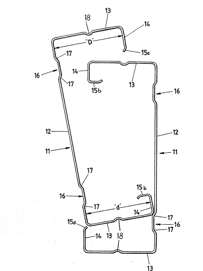
Referring first to Fig. 1, the hollow structural member 10 ~ :
comprises two identical member 'C'-section components 11 each
of which is formed from sheet metal and comprises a web 12
flanking two main flanges 13 each of which terminates along
corresponding edges in an inturned sub-flange 14, and each of
the sub-flanges 14 is provided with stiffening lips 15a and 15b
extending along its inner edge. (In some instances the lip 15a
is omitted.)
::
Each web 12 is provided with a pair of spaced ribs 16
defined by inwardly directed sloping wall portions 17, and upon
assembly, lips 15a and 15b of each of the 'C'-section ,;
components 11 engage respective outer and inner surfaces of the
;inwardly directed wall portions 17. It is this engagement
which assists inhibition of displacement of the contiguous main
flanges 13 Qf the two member components 11, even when no
. , .
fasteners are used to retain them.
The main flanges 14 are also provided with ribs 18 which
are desirable in the roll-forming, and also stiffen the main
flanges.
. .,. ~ ., . -
: .. .. , : : ~, .
, . ., , . . ,
....
~-~ 5 2~ ~7'~
The outside dimension 'd' across the width of one main
flange 13 which carries the inner of the lips 15 is two metal
thicknesses less than the corresponding width 'D~ of the flange
which carries the outer of the stiffening lips 15. With this
arrangement it is relatively easy for each component 11 to have
its inner stiffening lip inserted within the other, and the
outer stiffening lip over the outer surface of the other
component 11, and the stiffening lips then bear against the
inwardly directed wall portions of the ribs 16 to inhibit
disengagement.
The illustrations show the sections 11 each having been
'~ formed of identical cross-sectional shape by a roll-forming
process. However the invention is not necessarily limited to
the roll-forming process and in some embodiments it is
desirable to produce the sections by an e~trusion process, for
example of structural aluminium.
; The assembly which is shown provides a structural member
lO which has very substantial strength because if load is
applied vertically to the assembly of Fig. 2, upper and lower
chords of the structural member have double metal thickness and
the strength of the composite member is considerable even
, ; without the use of fasteners which may however be added to~ ~ 25 compensate for the shear forces which exist when the member is
subjected to loading. However for light duty purposes, it is
not necessary for the members to be joined together as a
composite structural member but each section can be used
individually and separately. This is of considerable advantage
in building operations for example wherein lighter sections are
required for some elements of the building and stronger
structural members for upper elements.
~" '.
In Fig. 3, identical section structural members are used
35 for posts 21, rafters 22, tie beams 23 and struts 24. The
purlins required are not illustrated.
'~ :
-' ~ :
.: ' . ': , , ' , . ' . ' ' . . . .. . . .. ' . . !j, . .
:
;` 6 2~22~
. .,~
.;~ . - .
A roof support bracket 25 comprises side plates 26 spaced
apart by two L-shaped spacers 27 to for~, in effæct, three
sockets 28 (for the post 21), 29 (for the tie beam 23), and 30
(for rafter 22). A ridge support assembly 32 co~prises plates
forming two sockets 33 for rafters, joined together by
fasteners through contiguous clamp plates 34. A space exists
between side plates 35 within which the upper end of strut 24
is contained. Side plates 36 intermediate the ends of tie beam
, 23 provide clamping means for the lower end of strut 24.
~10
Fig 4 illustrates a deflection testing arrangement wherein
; a structural member was compared with the illustrated prior
~` art. The representations are accurately drawn, and the overall
dimensions of the two sections were identical, the metal
thickness identical, but the Applicants' rolled section was
necessarily of a softer grade of aluminium (H34 standard half-
hard, compared with H16 structural grade). The relative -
~ strengths are as follows:
:',
Tensile H34 159 M.Pa
:' . i; :: i . Yield H34 134 M.Pa
Shear H34 97 M.Pa
` Tensile H16 179 M.Pa
APPLICANTS' H34 PRIOR ART H16
ROLL-FORMED ALUMINIUM EXTRUDED ALUMINIUM
LOAD DEFLECTION (f) LOAD DEFLECTION (f)
(KN)(INCHES) (KN) (INCHES)
WITH 1 0.070 1 0.080
FASTENERS 2 0.150 2 0.160
3 0.2~0 3 0.245
4 [0.310]* 3.5 [0.395]*
* [crushing occurred]
'~
.. . . . .
,:
- : , ~. : .
., ,
2~722~
~~ 7
~ ' ~
WITHOUT 1 0.075 1 0.045
FAS~ENERS 2 0.lS0 2 0.150
; 3 0.200 3 0.215
4 0.260 3.5 0.275
. .. .
APPLICANTS' GALVANISED STEEL
.~ .
i LOAD DEFLECTION (f)
;-j 10 (KN) (INCHES)
.: .
.:
WITH 1 0.050
,~ FASTENERS 2 0.070
~ ~ 3 0 090
`:~ 15 4 0.110
0.126
~ : 6 0.147
3,;; : 7 0.170
8 0.195
9 0.225
; ~ WIT80UT 1 0.040
FASTENERS 2 0.065
:~ 25: 3 0.080
4 0.100
~ ~ .
:~ ;5 0.115
: 6 0.140 ~ :
; 7 0.165 '.~ :
8 0.190 - :
8.5 0.210
-, . ~
The above tests were conducted independently by the
Australian National Railways at their Islington Laboratories in
South Australia, on 29th October, 1990. ~-~
.
They indicated: (1) A considerable increase in loading
before crushing occurred
' '
-:, '' ' ' ': '',", . ' ' ' ' ,, "', "i' . i,", '. ~ ., , :
8 2~7~
'; ' :
(2) A loss of strength without fas-teners
for aluminium, but an increase for
~`i` i
steel.
; 5 The conclusion reached was that the cross-sectional shape
. of Applicants' member was adequate to avoid the need for
fasteners.
~, The deflection/load ratio was within an anticipated range
for the steel, assuming a modulus of elasticity of 3x10⁷. The
; moment of inertia was less than could be obtained with a drawn
` tube having the same wall thickness as the combined thicknesses
; of the components, but the relative costs are much in favour of
Applicants' member for the same deflection.
~' ~
i ~ .. ;
, :
-i: : :.
,
:i ~
. ~
., ':
,~ ,
~,.. .... . . .
.
.. .