Note: Descriptions are shown in the official language in which they were submitted.
7 ~
,, 1
PULSATING LIOUID JET APPARATUS
Backaround of the Invention
Field of the Invention
This invention relates to fluid operated conduit
5 cleaning systems and, more particularly, to a valve unit
for producing high volume, high pressure, pulsed delivery
of a fluid, as for introduction into a conduit for
purposes of cleaning the inside passage thereof.
Bac~qround Art
opening of blocked and silted drainage, sewer and
other conduits is a vexatious problem that has plagued
the industry for many years. It is not uncommon for
conduits to run uninterrupted for hundreds of feet
without any access structure for cleanout. To further
aggravate the problem, these conduits may have one or
more sharp bends, which makes conventional rodding
techniques inadequate. A still further problem is that
frequently the obstructing material will be positively
adhered to the inside conduit surface. The use of a
flexible rod may do nothing more than bore a restricted
opening through the obstruction which thereby allows only
a limited flow volume.
To overcome the above problems, systems employing
high pressure fluid have been used. One such system
employs a flexible hose with a nozzle having one or more
passageways to produce a continuous, rearwardly expelled
fluid ~et. Such a system is shown in U.S. Patent
1,176,518, to Burns. Fluid is delivered under pressure
through the nozzle and directed thereby angularly
loutwardly with respect to the axis of the conduit. The
high pressure discharging fluid serves two primary
functions - 1) it effectively advances the hose through
the conduit and around sharp turns; and 2) it scours the
"~, , . , , . ., .. ... , ., , .,.,, " . . ., . , . , . - , .... .~. , .. . -. . . ~ . . - - .
?~7~
.
inside of the conduit wall to maximize the area of the
flow passageway. While the above system has proven very
effective, its principal drawback is that the nozzle may
not be able to penetrate or dislodge a tightly packed
obstruction.
To overcome the last mentioned problem, it is known
to provide an additional nozzle passageway to generate a
forwardly facing, high pressure fluid jet, as shown in
the above-noted Burns '518 patent, to blast through the
obstruction. It is possible with conventional technology
to employ this type of system to penetrate blocked and
heavily silted lines up to as much as 400 feet in length.
These systems are generally adequate for most industrial,
municipal, and household applications through manhole
access. However, this system may not be adeguate where
curves, elbows, and traps are encountered and/or when the
conduit length significantly exceeds 400 feet.
In order to enhance advancement of the nozzle,
particularly through a circuitous conduit pathway, and
breakup of obstructions, it is known to interrupt the
nozzle flow to produce a pulsed fluid delivery through
the nozzle. It is a known principal that repetitive
interruption of high pressure flow through a nozzle to
cause a pulsating action will result in the nozzle and
hose continuing to progress through a conduit and over or
around obstructions more effectively than can be achieved
by the steady pull obtained from a constant rearward
expulsion of fluid. ` s /'~
Several different mechanisms are;known in~the art
for producing pulsed delivery of a fluid. One such
- system is shown in U.s. Patent 4,838,768, to Flaherty.
Flahertyiemploys two pistons which alternatingly operate
to discharge fluid through an outlet. Pulses from the
separate pistons are timed to immediately follow one
another. It is also possible to disable one of the
.
: " ,
. ,~ '.
-
., i
~.
., ,~ .
~- 3
pistons to provide a lag between successive pulses by a
single one of the pistons.
The Flaherty system is relatively complicated. For
example, there are five check valves on the system and
multiple moving pistons. Failure of any element may
result in system malfunction. Another problem with the
Flaherty system is that it is inherently quite cumbersome
by reason of there being multiple pistons and flow
passageways associated therewith. It is a desirable
objective of planners of such systems to minimize their
size, due to the fact that most such systems are
regularly transported and used in the field.
Another prior art system is shown in U.S. Patent
1,796,941, to Pottenger, Jr. Pottenger, Jr. has a valve
that repetitively repositions to vary the discharge of
fluid through an outlet. Pottenger, Jr. notes on page 2,
beginning at lines 126 of his patent, that the valve, in
operation, never fully seats. Resultingly, there is no
sharp transition between pulse and no-pulse conditions,
which is desirable to effect positive advance of a nozzle
through a conduit. Instead, Pottenger, Jr. merely
produces a prQssure that increases and decreases to cause
an even radial distribution of water, as in a sprinkler
system such as that shown in the Pottenger, Jr. patent.
A further prior art device is shown in U.S. Patent
1,218,567, to Kellan. Kellan also employs a recipro-
cating closure which alternatingly seats and unseats to
produce pulsed delivery of an incoming supply of fluid
to a point of use. One drawback with Kellan is that once
the closure is seated no additional water 10ws from the
inlet towards the outlet. The result of this is the
, development of an air pocket immediately downstream of
the closure. Upon the closure unseating, the volume and
- pressure of the pulse is reduced over what it would be in
the absence of the air pocket. Pressure loss results in
::
.',..: ::,.-~':'
... . ~'""'` '.
. ~'. -,.
...
a less effective conduit cleaning and advancing action for a
nozzle.
Summary of the Invention
The present invention is specifically directed to overcoming
the above enumerated problems in a novel and simple manner.
According to the invention, a valve unit is provided for
producipg pulsed delivery of a fluid from a supply to a point of
use. The valve unit consists of: a valve housing defining a
main fluid chamber and inlet and outlet openings communicating
with the main fluid chamber; a piston movable between first and
second positions within the main fluid chamber for blocking
incoming fluid flow from the inlet opening through the main fluid
chamber to the outlet opening with the piston in its first
position and for allowing free communication of incoming fluid
flow from the inlet opening through the main fluid chamber to the
outlet opening with the piston means in its second position:
structure for repetitively moving the piston back and forth
between its first and second positions in response to a fluid
being supplied under pressure at the inlet opening, there being a
charge of fluid discharged through the outlet opening in the time
interval in which the piston moves out of its first position,
irto its second position and back to its first position.
In one aspect there is means for repetitively moving the
piston means back and forth between its first and second
positions in response to a fluid being supplied under pressure at
the inlet opening and includes bypass means for communicating
with the main fluid chamber at first and second locations at
first and second opposite ends of the piston means. The fluid
pressure on the second piston means end exerts a force tending to
move the piston means toward its first position and the fluid
! pressure on the first piston means and exerts a force tending to
move the piston means towards its second position.
In another aspect a bleeding structure communicates fluid
from the inlet opening to a location downstream of
the piston with the piston in its first position.
The above structure maximizes the pressure and volume
of each fluid pulse/charge. The bleeding structure
prevents the formation of air pockets downstream of
the piston. As a result, at the instant the
piston opens, the incoming fluid flow encounters a substantially
solid wall of fluid. In the absence of the
è:~
h O ~
bleeding feature, the incoming fluid would flow into an
air pocket so that the resulting pulse of fluid that
would be discharged before the piston moves back to its
first position would be diminished.
The present invention also contemplates a positive
acting valve unit that has a minimal number of moving
parts. In a preferred form, the piston is biased towards
its first position. The piston has a valve disc that
nests against a first valve seat in the main fluid
chamber and blocks incoming fluid flow from the inlet
opening through the main fluid chamber to the outlet
opening with the piston in its first position. The
piston has a main piston body movably mounted within the
main fluid chamber and a valve disc mounted movably
relative to the main piston body between a third
position, wherein the valve disc abuts a second seat on
the main piston body so that the valve disc follows
movement of the main piston body as the piston moves from
its second position towards its first position, and a
fourth position wherein the valve disc is spaced from the
~econd seat on the main piston body. The valve disc is
normally biased into its third position and has a first
pressure face and a seating face for nesting against the
rirst valve seat. The main piston body has separate
2S second and third pressure faces. The piston main body,
valve di6c, and structure for movably mounting the valve
disc and for movably biasing the valve disc make up a
part of the piston moving structure.
With the above assembly, the piston moving structure
is operable by incoming fluid flowing through the inlet
opening with the piston in its first position. The
lncoming fluid acts on the first and second presæure
face~ to urge the valve disc seating face against the
valve seat and, at a first predetermined incoming pres~
sure, causes the second valve seat on the main piston
...~. ,.".~ - ,"
....
2 ~ t,;~ ~ ,
body to move away from the valve disc against the valve
disc biasing structure. The biasing structure for the
valve disc includes structure for developing a pro-
gressively increasing force on the valve disc tending to
bias the valve disc into its third position as the valve
disc and second valve seat on the main piston body are
moved away from each other. The structure for developing
the progressively increasing force on the valve disc
causes the valve disc to unseat from the first valve seat
upon the second valve seat on the main piston body moving
a predetermined distance away from the valve disc
whereupon fluid from the inlet opening can flow freely
through the main chamber to the fluid outlet.
A bypass structure is provided for communicating
fluid with the main fluid chamber at first and second
locations, respectively downstream and upstream of the
piston. A portion of the incoming fluid flowing toward
the outlet opening enters the bypass at the first
location and flows through the bypass structure and out
at the second location to impinge on the third pressure
face until the pressure on the piston, urging the piston
towards its second position, equalizes with the fluid
pres~ure on the third pressure face urging the piston
towards its first position, whereupon the biasing
structure for the piston urges the piston back to its
first position.
A one-way valve is provided for b}ocking backflow of
fluid from the main flow chamber at the second location
through the bypass chamber to the main flow chamber at
the first location.
In a preferred form, the bleeding structure com-
,~ prises a ipassageway for communicating incoming fluid
through the valve disc toward the outlet opening with the
piston in its first position.
.,. : .
,,,
., ~, . .
... ~. . ., . . ., .~. .. ~.. .... ... . .. . . . . . ..
~~ 7 ::
. . .
The present invention also contemplates structure
for varying the length, maximum pressure, and volume of
each fluid pulse. This is accomplished by varying the
bias force exerted by the biasing structure on the
piston, which force tends to urge the piston towards its
first position.
This adjusting structure is preferably in the form
of a second piston which is movably mounted relative to
the housing to control the compression of a coil spring
acting between the first and second pistons. Movement of
the piston is preferably accomplished by a rod threaded
through the housing and having an external control head
through which the rod and associated second piston can be
repositioned.
Preferably, the force of the coil spring on the
second piston can be reduced to the point that the first
piston cannot realize its first position. This allows
the elimination of the crisp division between the pulses
and allows the valve to be adjusted to a no-pulse,
relatively constant flow condition. -
To facilitate placement of the coil spring between
the pistons, the first piston is preferably provided with
a blind bore to accommodate the coil spring.
The present invention also contemplates a valve unit
for producing pulsed delivery of a liquid and consisting
of: a valve housing defining a main fluid chamber and
inlet and outlet openings communicating with the main
fluid chamber; a piston with first and second opposite
ends movable between first and second positions within
the main fluid chamber for blocking incoming fluid from
the inlet opening through the main fluid chamber to the
outlet opening with the piston in its first position and
for allowing free communication of incoming fluid flow
from the inlet opening through the main fluid chamber to
the outlet opening with the piston in its second
., ,
,':.~.'~,',''.- "-
:'' , ;~.
2 '~ ~
~ 8
!
position, there being a charge of fluid that is dis-
charged through the outlet opening in the time interval
in which the piston moves out of its first position into
its second position and back to its first position; and
structure for repetitively moving the piston back and
forth between its first and second positions in response
to a fluid being supplied under pressure at the inlet
opening and including bypass structure for communicating
with the main chamber at first and second locations at
the first and second opposite piston ends. The fluid
pressure on the second piston end exerts a force tending
to move the piston towards its first position and the
fluid pressure on the first piston end and exerts a force
tending to move the piston towards its second position.
It is another object of the invention to provide a
versatile valve structure that can be selec$ively
provided with and without an adjusting capability. To
accomplish this end, a generic housing is designed to
accept a removable end cap. The end cap can be provided
with part of the bias adjusting structure on the piston.
Alternatively, a cap without any ad~usting structure can
be employed which fixes the operating characteristics for
the valve unit.
~r~e~_~escription of the Drawings
Fig. 1 is a schematic representation of a conduit
with a valve unit for producing pulsed delivery of a
fluid from a supply according to the present invention
incorporated therein;
Fig. 2 is a cross sectional view of the inventive
valve unit with a movable piston thereon in a first
, ~position;,
Fig. 3 is a view similar to that in Fig. 2 with the
piston in a second position; and
~'
...
,~
"'` ' ,: -
... ..
7 2 ~ ~ :
....
: ., .
Fig. 4 is a cross-sectional view of a modified form
,.. - - ,
of valve unit according to the present invention, with an
adjusting capability incorporated therein.
Detailed Description of the Drawinas
Fig. 1 is a schematic representation of a conduit
cleaning system at 10 in association with a length of
conduit 12. The system 10 incorporates an in line valve
unit 13, according to the present invention, for
producing pulsed delivery of fluid from a pressurized
supply 16 through a flexible supply hose 18 to a nozzle
20. The nozzle 20 is directed through the open end 22 of
the conduit 12 and advanced lengthwise therewithin in
operation.
The nozzle 20 has a lengthwise bore 26 with a fluid
outlet 28 at the rounded, leading end 30 thereof. The
nozzle 20 has spaced passageways 32, 34 for directing
separate jets of fluid 36, 38, respectively, angularly
rearwardly from the nozzle 20 to impinge on the inside
surface 40 of the conduit 12. While two jets 36, 38 of
fluid are shown, any number of fluid jets 32, 34 can be
developed in circumferentially spaced relationship about
the nozzle 20. The fluid impinging on the inside conduit
surface 40, at the angle shown in Fig. 1, causes the
nozzle 20 to advance in the direction of` arrow 42 in Fig.
1. At the same time, the fluid jet 44, emanating from
the leading end 30 of the nozzle 20 impacts obstructions
in front of the nozzle 20 to effect breakup thereof and
de~ine an opening therethrough into which the nozzle 20
can pass. The ~ets 36, 38 at the same time scour the
inside conduit surface 40 as the nozzle 20 advances
within the conduit 12. By drawing rearwardIy on the~hose
18, the ~ets 36, 38 are caused to effectively "scrape"
the inside surface 40 of the conduit 12.
, .
: -
,~,
,,, . ~ - ~ -
~ . . .
,
: ,
2 ~ ~ ~
It is well known that if high pressure flow in a - -
nozzle is interrupted on a repeated basis, 80 as to
produce pulsed delivery of fluid, the advancement o~ the
nozzle will be enhanced, particularly around curves,
elbows, traps and the like. The present invention is
directed to the structure 13 for causing the pulsed
delivery of fluids from the supply 16 to the hose 18 and
nozzle 20.
As will be seen hereafter that one extremely
desirable feature of the present invention is that it is
very compact, with a minimal number of moving parts. It
can be simply spliced into an existing high pressure line
to produce the pulsed output of fluid. '!;~
A first version of the inventive valve unit is shown ~3
in Figs. 2 and 3 at 13. The valve 13 consists of a -~
housing 46 having a square, round, or other suitable
cros~-sQctional configuration. The housing 46 has a
stepped through bore 48 with a small diameter bore
sQction 50 and a large diameter, concentric bore section
52. The bore sections 50, 52 together define a main
fluid chamber 54 having an inlet opening 56 and outlet
opening 55 in communication therewith. Fluid from the
supply 16 flows through the inlet opening 56 into and
through the chamber 54, through the outlet opening 55 to
the hose 18 and ultimately to the nozzle 20.
Within the main fluid chamber 54 is mounted a piston
mQans at 58 that is movable between a first position
tFig. 2) and a second position (Fig. 3). The piston ~,~
means 58 consists of a main piston body 60 with a stepped -~
configuration including a cylindrical first section 62
and an enlarged second section 64. The first piston body
section 62 has a blind, threaded bore 66 therein which -
accepts the threaded end 68 of a shoulder bolt 70. The
bolt 70 has a body 72 of substantially uniform diameter
with the diameter thereof being larger than the diameter
"`"'~`~ -
. . -~ .,
" .
. . ,
~ r,~
'''~\` 11
':
of the threaded bolt end 68. At the juncture of the
threaded end 68 and body 72, an annular shoulder is
defined for abutment with the free end 76 of the piston
body 60.
The bolt 70 has an enlarged head 78 defining an
axially facing, annular shoulder 80. The bolt 70
supports a valve disc 82 which closely surrounds and is
slidable guidingly lengthwise over the bolt body 72.
With the bolt 70 assembled to the piston body 60, the
valve disc 82 is captively maintained between the free
end 76 of the piston body 60 and the shoulder 80 on the
enlarged head 78 on the bolt 70. A coil spring 84
surrounds the bolt body 72 and acts between the valve
disc 82 and shoulder 80 to bias the valve disc 82 into a
third position against the free end 76 of the piston body
60.
The open end 86 of the housing 46 is sealed by an
end cap 88 having an annular extension 90 with an axially
opening blind bore 92 therein. The piston body 60 has a
blind bore 94 that is coaxial with the bore 92 in the end
cap 88. A coil spring 96 is interposed between the wall
~urfaces 98, 100, respectively at the bottom of the bores
92, 94. The coil spring 96 normally biases the piston
means 58 into the Fig. 2 position. The end cap 88 is
removably held seCurely in place on the housing 46 as by
bolts 102, 104.
A bypass chamber 106 is provided in the housing 46
and communicates with the main fluid chamber 54 between
a first location 108 downstream of the piston means 58
and a second location 110 upstream of the piston means
58.
! A three-step bore 112 communicates between the
bypass chamber 106 and the main chamber 54 at the first
location 108. First and second bore sections 114, 116,
respectively, define an annular seat 118 for a plunger
'
.- ..
2 ~ ~?
ri~ 12
120 on a one-way valve 122 that is normally urged by a
coil spring 124 into the closed position shown in Figs.
2 and 3. The valve plunger 120 has a control orifice 123
therethrough to maintain communication between the fir6t
S and second locations 108, 110 in the main fluid chamber
54. The diameter of the orifice 123 dictates the pulse
rate, as will be evident from the description below.
With a predetermined pressure buildup in the chamber 54
at the first location 108, the plunger 120 is caused to
unseat to open communication between the main chamber 54
and the bypass chamber 106. A plug 126 is threaded into
the housing 46 to permit assembly and/or repair of the
one-way valve 122.
m e operation of the valve unit 13 is as follows.
lS Fluid from the supply 16 is introduced through the inlet
opening 56 with the piston means 58 in the first position
of Fig. 2. With the piston means in its first position,
a seating face 128 on the valve disc 82 bears sealingly
against an annular seat 130 defined by the stepped
through bore 48. Upon the pressurized fluid being
introduced from the supply 16, it impinges upon a first
pressure surface 132 on the valve disc 82 and an
oppositely facing, second pres6ure surface 134 on the
piston body 60. As the pressure builds at the inlet
opening 56, the fluid urges the piston body 60 to the
right in Fig. 2 while at the same time maintaining the
valve disc 82 in its seated, Fig. 2 position. The
pressure buildup from the piston body 60 causes a
di~charge of fluid through the orifice 123 at the first
location 108. Movement of the piston body 60 compresses
spring 96 80 as to increase the restoring force therein,
,and also ~compresses the coil spring 84 between the valve
disc 82 and enlarged head 78 on the bolt 70. Upon a
predetermined movement of the piston body 60 away from
the seated valve disk 82, the coil spring 84 causes the
...~ :.. .
~ 13
!
valve disc 82 to unseat, as shown in Fig. 3, which
thereby allows free flow of fluid through the opening
136, previously blocked by the valve disc 82, and through
the outlet opening 55. Upon the valve disc 82 unseating,
the seating face 138 of the valve disc 82 is exposed 60
that the incoming fluid forces the valve disc 82 back
against the free end/seat 76 of the piston body 60, to
its third position shown in Fig. 3.
There is sufficient back pressure in the hose 18 to
allow a pressure buildup in the bore section 50 at the
first location 108. Upon a predetermined pressure
buildup, the plunger 120 is caused to move against the
coil spring 124 to allow fluid passage from the bore
section 50 through the bypass channel 106 and against a
third pressure surface 140 at the end 142 of the piston
means 58. Once the bypass channel 86 causes pressure
equalization between the end 142 of the piston means and
the opposite end 144 of the piston means 58, the
compressed spring 96 drives the piston means 58 from the
Fig. 3 position back to the Fig. 2 position. In the time
interval in which the piston means 58 moves from its
first position into its second position, and back to its
first position, a charge of fluid is discharged. This
process repeats as long as fluid is introduced under
pressure at the inlet opening 56.
one important feature of the present invention is
the provision of a bleeding means 146 that functions with
the piston means 58 in the first, closed position of Fig.
2. The ~leeding means consists of a non-axial passageway
which allows fluid flow from the inlet opening 56 through
the valve disc 82 and into the bore section 50 with the
piston means 58 in the closed position of Fig. 2. The
significance of this is that the bore section 50 and hose
18 remains substantially filled with fluid, even with the
piston means 58 in the closed position of Fig. 2. As a
, "-~"''~'. ':
' ~.
~ ~3 ~ J
14
consequence, immediately upon the valve disc 82
unseating, the incoming fluid from the supply 16 is
caused to produce a pulse of fluid through the outlet
opening 55 and nozzle 20. This maximizes the flow volume
and pressure for each pulse. In the absence of the
bleeding means 146, an air pocket would be present on the
downstream side of the valve disc 82 with the piston
means 58 in the closed position of Fig. 2. In that case,
unseating of the valve disc 82 will cause the pressure of
incoming fluid to be dissipated by reason of it flowing
into the air pocket before any fluid pulse could be
created at the nozzle 20. The result is a reduction in
the pressure of the pulse and the volume of fluid moved.
To prevent fluid leakage in an axial direction
around the enlarged section 64 on the piston body 60, a
sQaling 0-ring 148 is provided in an undercut 150 tQ seal
between the outer surface 152 of the section 64 and the
guiding surface 154 therefor on the housing 46. A seal
156 i8 also provided between the end cap 88 and the
housing 46 to prevent leakage.
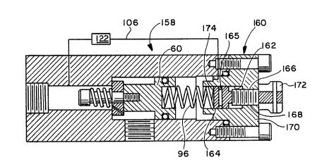
A modified form of valve, according to the present
invention, ~8 shown at 158 in Fig. 4. The principal
distinction between the valve 158 and valve 13 shown in
Figs. 2 and 3 is a modification to the end cap at 160
which allows for variation in the force of the spring 96.
The end cap 160 has a stepped through bore 162 with a
~econd piston 164, with a sealing O-ring 165 thereon,
movable guidingly axially along the bore 162. The bore
162 has an associated rod 166 threaded in a bore 168
through the cap body 170. An exposed control head 172 is
attached to the rod 166 to facilitate its rotation.
The coi} spring 96, described earlier, is interposed
between the piston body 60 and an axially facing surface
174 of the second piston 164. By turning the rod 166
through the control head 172, the piston is caused to be
:: :
. -, .
.,,,",
:- '. ' - -:
., ., . ,. , . - ,
~,:
;, ~ ' .
~' 15
moved 6electively in opposite axial directions. Movement
of the rod 166 to the left in Fig. 4 increases the
compressive force on the spring 96 to thereby shorten the
fluid discharge interval and resulting pulse, whereas
opposite movement of the rod 166 lengthens the fluid
discharge pulse. The end caps 88, 160 are
interchangeable and can be selectively placed on the
housing 46 by the user depending upon whether the
ad~usting capability is desired or not.
After repeated opening and closing of the piston
means 58, there is residual pressure buildup at the one
piston body end 142 due to the entrapment of fluid at the
downstream end of the main chamber 54. This consequently
limits the stroke of the piston means 58 to thereby vary
the pulse length. As previously described, this pressure
buildup is relieved through the orifice 123. The opening
and closing action of the piston means 58 is, in addition
to being controllable by the adjusting structure
associated with the end cap 160, controllable by varying
the diameters of the first bore 114 and orifice 123 and
the spring constant for spring 124. By having the bypass
circuit actuated with a smaller pressure in the bore
section 50, the pulse length is reduced.
The foregoing disclosure of specific embodiments is
intended to be illustrative of the broad concepts
comprehended by the invention.
,
. . - . . ~,:
-, . . ~, ,
`:
";'P',; ' ~'::
: :,
~ '`
~-` i
' ' "' : ~ :
~;