Note: Descriptions are shown in the official language in which they were submitted.
2 0 ~ 7 3 ~ ~
-- 1 --
HI&ll EFFICIENCY WATER HEATER
In a conventional gas fired water heater, a gas
burner is located beneath a lower end of a water tank
in a header space. A central vertical flue is
provided through the tank for discharge of waste
; combustion or flue gases. Water in the tank is heated
by heat from the burner in the lower header space and
from the waste gases passing upwardly through the
central flue.
Considerable heat losses occur during non-use
or standby periods with conventional gas fired water
heaters.~ Since all of the water in the tank is heated
to the same pre-set temperature, large amounts of
energy are expended to keep the volume of water at
this temperature. Also, heated water rises to the top
of the tank by convection causing the water to
stratify and become overheated at the top of the
tank. Drawing limited amounts of water from the top
of the tank may result in overheated water being
delivered. With a single central flue, although some
increase in heating efficiency is gained by heat
transfer from the flue gases, this is limited to that
amount of heat which can be transferred to the water
in close proximity to the central flue.
U.S. Patent 4,676,199, issued June 30, 1987 to
Daugirda et al. and assigned to Rheem Manufacturing
Company discloses a multistage, high efficiency, gas
fired~water heater including a lower primary heating
tank and an upper secondary heating tank. A plurality
of primary flues are provided through the primary tank
which are aligned with secondary flues in the
secondary tank. Manifolds are situated above, below
and between the tanks. One of the primary flues is
constructed to operate as a condensate removal pipe
for draining water from the secondary flues. This
water heater design is complicated by the provision of
~}~
,, , ~ . .
.. ..
~ ' ' ' '
20~73~
-- 2 --
both primary and secondary flues in both tanks. The
flues must be aligned and of different diameters for
proper functioning.
~ There is a need for a relatively simple high
; 5 efficiency gas fired water heater which utilizes
multiple stages to heat the water, while maintaining
~1 the simplicity of the central flue design.
;~ In accordance with the present invention a gas
fired water heater is provided which includes a lower
storage tank and an upper recovery tank within an
nsulated housing. Cold water is provided through
inlet means into the recovery tank and heated water is
removed through outlet means from the storage tank.
The recovery and storage tanks are interconnected to
I5 transfer heated water from the recovery tank to the
storage tank. A central flue is provided through both
tanks. A plurality of secondary flues are located in
the upper recovery tank. Scraping chambers are formed
above, below and between the tanks in communication
with the central fIue. With this design, heated
combustion gases from the burner mounted below the
storage tank heat the water in the storage and
recovery tanks from both the central and secondary
flues and through the scraping chambers. The lower
storage~tank acts as a booster, holding a volume of
water at a pre-set temperature above that of the water
in the recovery tank.
The lower ends of the storage and recovery
tanks and the upper end of the housing are preferably
convex shaped such that heated combustion gases are
diverted from the central flue to the scraping
chambers.~ Deflectors are preferably provided in the
flues and the diameter of the central flue is
preferably narrowed adjacent the upper end of the
; 35 recovery~tank to slow the passage of the heated
combustion gases in the flues and to divert the gases
into the scraping chambers and the secondary flues.
: ::
,: ':: ' . -
,
:. ;, '" ~' ''' ;; ~' . '
--- 20473~a
-- 3
The scraping chambers are preferably shaped such that
the opening into each chamber from the central flue is
larger than the opening formed by the central flue or
the vent means. This preferred design causes the
; 5 heated combustion gases to mushroom into the scraping
chambers above and below the tanks to more completely
envelope the storage recovery tanks and deflect the
gases into the secondary flues and to maximize heat
transfer efficiency to the water in the tanks before
the gases are vanted. The storage tank can be
downsized from that of a single tank water heater to
maximize heat efficiency at peak draw times, while
minimizing heat losses during standby or low use times.
In an alternative embodiment a valve means may
be incorporated between the lower end of the recovery
tank and the upper end of the storage tank, in a
conduit extending therebetween, preferably in close
proximity to the temperature probe. The valve
includes an orifice or crevice so that a minimum
quantity of cold or cooler water may be transferred
from the upper tank to the lower tank (when hot water
has been drawn for use) which transfer will activate
the burner through the change in temperature. In
addition, when water is not being drawn, an open
circuit is created via the orifice, whereby through
thermo-syphon action the upper recovery tank may be
preheated with relatively warmer water from the
storage tank. The orifice is normally provided in a
plunger of the valve which may be springloaded, if
desired. By this latter action, the lower tank works
as a booster, and the upper tank as a main recovery
. ~ .
tank. In this action, the cooling is not sufficient
to create condensation. This is an important factor
as it permits the use of steel tanks as opposed to
~ .
stainless steel tanks. The upper tank is larger in
size, tempering cold water and maximizing recovery.
Broadly stated, the gas fired water heater of
;~'
:; .
.
.
20~7~
-- 4
this invention comprises an insulated housing having
upper and lower ends; burner means in the housing
adjacent its lower end for burning gas and producing
heated combustion gases; a storage tank in the housing
above the burner means; a recovery tank in the housing
above the storage tank; vent means at the upper end of
the housing; a flue located centrally in the housing
and extending from the burner means to the vent means
through the storage and recovery tanks; a first
scraping chamber formed adjacent the burner means in
open communication with the central flue and in heat
; transfer relationship with the bottom of the storage
tank; a second scraping chamber formed between the
storage and recovery tanks in open communication with
the central flue and in heat transfer relationship
:~ with the top of the storage tank and the bottom of the
recovery tank; a third scraping chamber formed above
~; the recovery tank in open communication with the
central flue and in heat transfer relationship with
the top of the recovery tank; a plurality of secondary
flues extending through the recovery tank between the
second and third scraping chambers; water inlet means
for introducing cold water to the lower end of the
: recovery tank; water outlet means for removing heated :-
:~ 25 water from the upper end of the storage tank; and
water transfer means for transferring water from the
upper end of the recovery tank to the lower end of the
storage tank.
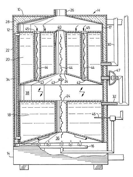
Figure 1 is a vertical section of a water
heater of the present invention, and
~:~ Figure 2 is a vertical section of an
alternativé form of the water heater of Figure 1.
: : one preferred embodiment of the present
~ invention is shown in Figure 1 wherein water heater H
; 35 includes a housing 10 having upper and lower ends 12,
14 respectively. A burner 16 adapted to combust gas
~:` such as natural gas or propane or some other
'
: .
,
, ,
: :. ~ .
~ ,~
2~735~
combustible material such as oil is located at the
lower end 14. While the invention is disclosed in
respect of a gas-fired water heater, it is equally
applicable to water heaters which burn other
combustible fuels. Such water heaters are intended to
fall within the scope of the claims. The housing 10
includes an inner tank 17 and an outer casing 22. A
storage tank 18 is formed in the housing 10 above the
burner 16. A recovery tank 20 is formed in the
housing 10 above the storage tank 18. A central flue
24 extends vertically from the burner through the
storage and recovery tanks 18, 20. A vent 26 is
provided at the upper end 12 of the housing 10 to vent
combustion gases from the water heater H. The vent 26
is preferably centrally positioned above the central
flue 24, as shown in the drawing. The flow of
combustion gases within the housing 10 is preferably
by convection only, the vent 26 communicating with a
chimney (not shown). A mechanical draft unit (not
20 shown) may be used for forced flow should it be ;~
'~ desirable to vent gases directly through an exterior
wall of a building. The tanks 18, 20 are surrounded
by insulation 28 within the housing 10 between the
outer casing 22 and the inner tank 17.
A water inlet 30 leads into the lower end of
the recovery tank 20 for introducing cold water
thereto. The water is preferably distributed evenly
~.
through a distributing head (not shown) to prevent
cold spots at the inlet which can lead to condensation
from the combustion gases. The water inlet 30 and
optional distributing head defines a water inlet means
;~ ~ for introducing cold water to the lower end of the
recovery tank 20.
A water outlet 32 is located at the upper end
of the storage tank 18 for removing heated water
therefrom. This outlet 32 defines a water outlet
means for removing heated water from the upper end of
~'` ::~
'
,
.
:
.
.: '
-~"` 2~'~73~
-- 6 --
: the storage tank 18.
: A water transfer pipe 34 extends from the upper
~ end of the recovery tank 20 to the lower end of the
:~ storage tank 18 and defines a water transfer means for
: 5 transferring heated water from the upper end of the
recovery tank 20 to the lower end of the storage tank
18.
: A first scraping chamber 36 is formed adjacent
~ the burner 16 below the storage tank 18. The chamber
:~ 10 36 is open to the central flue 24. Heated combustion
~ gases produced by the burner 16 impinge:against thè
- bottom of the storage tank 18 to cause heat transfer
therethrough to the water in the storage tank 18. A
second scraping chamber 38 is formed between the
. 15 storage and recovery tanks 18, 20 in open
communication with the central flue 24. Heated
combustion gases rising in the central flue 24 enter
the chamber 38 to cause heat transfer through the top
i~ of the storage tank 18 and the bottom of the recovery
tank 20 to the water in these tanks 18, 20. A third
scraping chamber 40 is formed above the top of the
recovery tank 20 in open communication with the
:~; central flue 24. Heated combustion gases rising in
the central flue 24 enter the chamber 40 to cause heat
transfer through the top of the recovery tank 20 to
~ ~ :the:water in the recovery tank 20.
;~ A plurality of secondary flues 42 extend
through the recovery tank 20 between the second and
third::scraping chambers 38, 40. In the embodiment
30 shown~in~the drawing, four secondary flues 42 are
spaced equidistantly around the central flue 24, two
being shown in the vertical cross-section. However,
: the number~may be varied according to the size of the
tank 20 and the desired heat transfer efficiency.
Heated combustion gases in the second scraping chamber
, ~
~- 38 rise through these secondary flues 42 to further
~: : heat the water in the recovery tank 20. Thus, water
~ ,
::~ ' " ': , ' " '
:,, .
:: : - :-:- :
204~3~
in the recovery tank 20 is heated by heat transfer
from the heated combustion gases enveloping tank 20
from the bottom and top thereof, the central flue 24,
and the secondary flues 42. Water in the storage tank
S 18 is heated by heat transfer from the heated
combustion gases enveloping the tank 18 from the
central flue 24 and the top and bottom of the tank 18.
Deflectors or baffles 44 of conventional design
such as twisted metal ribbons are located in both the
central and secondary flues 24, 42 to slow down the
flow of the combustion gases and improve heat transfer
~;- through the flues. The deflectors 44 are preferably
hung from a T-bar 45 from the top of the flues 24, 42
.,
such that they can be removed for cleaning as needed.
~part from the deflectors 44, a number of
additional preferred features may be included to slow
- ~:
down the flow of the combustion gases and to cause
~- combustion gases to mushroom into the scraping
;~ chambers 36, 38, 40 and be diverted into the secondary
flues 42 in order to maximize heat transfer through
these areas. Firstly, the diameter of the central
flue 24 may be restricted adjacent the upper end of
the recovery tank 20/ either by tapering as shown at
` ~ 47 in Figure 1 or by a deflector (not shown), either
of which would define restricting means on the central
- flue to narrow the diameter of the central flue
adjacent the upper end of the recovery tank 20.
Secondly, the openings from the central flue through
which the gases enter or mushroom into the scraping
~- 30 chambers 36, 38, and 40 may be preferably larger than
the openings~formed by the central flue 24 or the vent
26. Thirdly, the bottoms of the storage tank 18 and
the recovery tank 20 are preferably convex in shape,
that is they extend downwardly and outwardly from the
central flue 24 to their outer perimeter. These
features combine to form scraping chambers sized and
~ ~ shaped to divert or mushroom the heated combustion
;: ~
, -
;.; ~ :
,: .
~: . , : ; :
: .
~ 20473~
gases from the central flue 24 into the chambers and
the secondary flues for maximum heat transfer.
A temperature probe 46, of conventional design
is preferably located in the upper portion of the
storage tank 18 to sense the pre-set temperature and
control the burner 16 in response thereto. The water
heater H of this invention is preferably operated at
temperatures sufficiently high so as to discourage
condensation of water vapour from the combustion
gases. This enables the tanks 18, 20 and flues 24, 42
to be formed from standard steel or other heat
conductive material. However, if greater heat removal
from the combustion gases is desired, which would
cause condensation in the heater, a drainage system as
envisaged in U.S. Patent 4,676,199 could be used to
collect condensate from the second scraping chamber 38
and drain it from the heater H and stainless steel
could be used as the heat conductive material for the
tanks 18, 20 and the flues 24, 42.
~` 20 It will bs appreciated that the storage tank 18
has a booster effect on demand water. Firstly, the
reduced size and the shape of the tank 18 maximize
; heat transfer as heated combustion gases envelope the
tank 18 from the scraping chambers 36, 38 and from the
central flue 24. Secondly, the reduced size of the
tank 18 increases energy efficiency as a lower volume
of water is held at the pre-set temperature in
.
stand-by periods.
Referring now to Figure 2 of the drawings,
there is shown an alternative embodiment. In this
drawing, there is shown a~water heater which has a
; ~ structure identical to that shown in Figure 1 except that a valve 47 is located within a conduit 48 which
extends between the base of the recovery tank 20 and
~: .
the top of the storage tank 18. The connection to the
storage tank 18 is made preferably at a point in close
proximity to the temperature probe 46. A plunger 49
~, . ~, .
~ . ,
: ~ :
. ' :' . . '.~ ` ~ ~
', - :
2OL~73~
g
forms part of valve 47, which optionally may be
springloaded. When the water temperature in the
recovery tank 20 is lower than the water temperature
in the storage tank 18, an orifice (not shown) in
plunger 49 of the vaIve 47 permits flow of cooler
` water from the recovery tank 20 into the storage tank
18 thereby activating the burner 16 through the
temperature probe 46. If the temperature of the water
in the storage tank 18 is higher than in the recovery
tank 20, water will pass through the conduit 48
through the orifice into recovery tank 20 by
thermo-syphon action. By this action, the storage
tank 18 acts as a booster tank for the upper main
recovery tank 20. In this action, the cooling is not
sufficient to create condensation. The upper tank 20
is larger in size, tempering cold water and maximizing
recoveryO
The present invention has been disclosed with
reference to a single storage tank 18 and a single
recovery tank 20, however, it is within the skill of
one in this art to construct a water heater with a
pluralitv of either or both of these tanks. Such
~; variation is included within the scope of the present
claims.
"~ 25 It is also possible that the storage and
recovery tanks 18, 20 could be spaced from the walls
of the housing 10 to allow for more complete
envelopment by the flow of the combustion gases around
the entire surface of the tanks 18, 20.
While the present invention has been shown and
described with reference to its preferred embodiments,
the invention is to be limited only by the following
claims and their equivalents.
~ ,
`::
:::
:~ '
: ~:
,.
- .
:
, ; '
' :
.