Note: Descriptions are shown in the official language in which they were submitted.
The present invention relates to the field of
intravenous supply alarm systems.
Intravenous supply systems are widely used in medical
treatments to supply nutrients, drugs, blood or blood products,
etc. to patients. While intravenous tIV) supply systems h~ve been
used for many years, several improvements have been made to
increase the safety and utility of the systems. The most notable
improvement has been the disposable IV supply system.
Disposable IV systems are commcnly ~abricated from a
clear thermoplastic material which is formed into a bladder or
bag. The appropriate tubing and needle are integrally attached
and the bladder is pre-filled with sterile intravenous fluids and
is thus self-contained, requiring no extra equipment when used.
The plastic material and construction techniques
employed allow the disposable IV supply systP~ to he fabricated
at a minLmal cost. They are thus immediately ready to use, when
ns~ded and may be con~eniently discarded after use, removing any
possibility of contamination of the supply or infection of a
patient through reuse.
However, a problem exists with IV supply systems in
general in that when the IV supply is exhausted, there is a
possibility that an air bubble may be allowed to enter the
patient's vein through the feed tubing. This air bubble may lead
~'173~7
to the formation of an air embolism with seriou~ consequences to
the patient.
Thus, it is necessary for medical personnel, or the
patient, to closely monitor the level of ~luid in the supply at
all times. Placing this responsi~ility on the patient leads to
increased anxiety and general discontent with the use of the IV
supply systems. ~here have been several prior attempts to
overcome the problem of monitoring the supply level in IV systems.
U.S. Patent 2,706,755 to Xrasno shows an alarm device
from which an intr~venous supply bottle is hung. The device has a
moveable plate which is biased by a spring against two electrical
contacts to complete an electric alarm circuit. The supply ~ot~le
i5 suspended from a hook attached to the platQ and the weight of
the bottle and its contents act aqainst the spring to move the
plate away from the electrical cont,cts, opening t~e circuit. As
the contents o the supply bottle are fed into the patient, the
weight acting against the spring is reduced and the plàte moves
towards the electrical contacts. When the supply is almost ful.ly
di placed from the bottle, the weight is reduced to the point that
the plate completes the circuit and activates the alarm.
U.S. Patent 3,389,387 to Hulse et al. shows a similar
alarm device which monitors changes in the weight of the supply
container due to changes in the amount of supply fluid. As the
container empties, a spring biased member is moved from a position
~0~7;~ ~ 7
in contact with a circuit-opening switch to a position out of
contact with this switch thus closing the circ~it and signalling a
medical attendant.
U.S. Patent 3,3gO,238 to O'Neill shows a fairly complex
alarm device which is adjustable to accommodate supply assemblies
of different weights, due to differing amounts of supply fluid
and/or dif~erent densities of various supply fluids.
These prior alarm devices all suffer from numerous
disadvantages in ~ractise. Firstly, they are bulky units,
separate from the IV containers, which must be set up in
association with the IV containers prior to use. In current
medical practice, however, it is desirable that all treatments and
apparatus be self-contained whenever possible. Secondly, they
~Nst be re-used and transferred from one IV container to the next
thus increasing the li~elihood of breakage. Thirdly, repeated use
o~ these units neces~itates repairs and performance monitoring.
Fourthly, these units are expensive to manufactNre wi~h numerous
and detailed component parts. Due to the aforementioned problems,
these devices have not attracted significant commercial ~nterest.
It is an object of the present invention to obviate or
mitigate the above disadvantages.
The present invention provides an intravenous supply
assembly comprising a bladder adapted to contain an intravenous
2 ~ ~ 7 ~ ~ 7
fluid, a support means extending from the bladder and an alarm
means associated with both the bladder and the support means, said
alarm means operating to provide a signal when the volume of the
intravenous fluid in the bladder is less than a pre-defined
minimum.
In a preferred form, the alarm means comprises spaced
contacts, an upper contact associated with the support means and a
lower contact associated with the bladder, said spaced contacts
being movable into electrical engagement when the ~olume of the
bladder reaches a level at which it i5 deemed appropriate to
notify medical personnel so as either to disconnect the
intraveneous supply assembly from the patient or to replace the
u~ed bladder with a new bladder. In a very pref~rred form, the
al ~m means is secured to and more preferably partially or fully
integral with the bladder and the support maans.
The intravenous supply assembly of the present invention
is a simple and effective warning system for patients and medical
personnel aliXe. The use of the alarm means as described herein
significantly reduces the chance of an unchecked, empty
intravenous bladder pas~lng air into the vein of a patient to
which it is a~tached. The alarm means is designed to comprise a
minimal number of parts so that in the preferred form, it can be
manufactured, sold and ultimately discarded with ~he intra~enous
bladder and support means.
2~l~73~7
A preferred embodiment of ~le present invention will now
be discussed, by way of example only, with reference to the
following ~igures wherein:
Figure 1 shows an intravenous supply assembly;
Figure 2 shows a schematic of an electrical circuit ~or
the assembly shown in Figure 1;
Figure 3 shows another embodiment of an intravenous
supply assembly;
Figure 4 shows the engaged contacts of the assembly of
Figure 3.
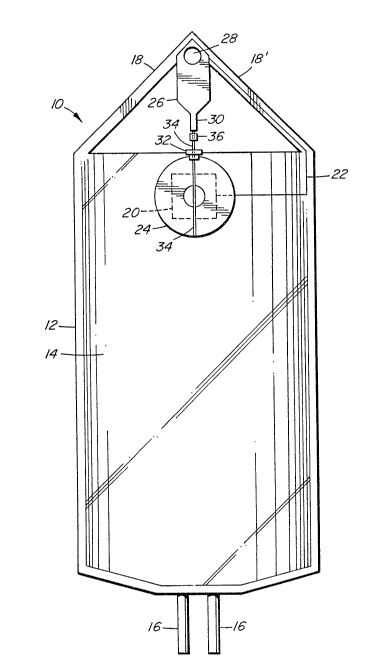
In Figure 1, an intravenous supply asse,mhly is indicated
generally at 10. The supply assembly consists of a bladder or bag
12 containing the intravenous ~luid 14, tubing 16 for attachment
to the intravenous cathe~er, not shown, and support arms 18,18'
from which the supply is suspended.
A battery 20 is pref~rably wafer-shaped with each side
of the wafer being one terminal of the battery. One texminal, the
positive for example, has an insulated conductor 22 electrically
connected to it and is bonded to one side of the bag 12, near it.
top, between the points where the support arms 18,18' connect to
the bag 12. Thus the positive terminal of the battery, ln ~1-S
case, abuts the bag 12.
A buzzer or beeper 24, preferably of the piezoelectric
type, is bonded to the battery 20 in such a ~ashion that one
electrical terminal o~ the buzzer 24 is in electrical contact wi~h
the other terminal of the battery, in this case the negati~e
terminal.
The conductor 22 is arranged to connect to a flange 26
located at the vertex formed by the support ar~s 18,18'.
Preferably, the flange is of metal.
The metal flange 26 is attached to the support ~rm~
18,18' to which the conductor 22 is electrically conn~cted. The
flange 26 has a hole 28 at its upper extremity through which, when
the supply ass~hly is in use, a support hook may be placed. Thus
the weight of the supply assembly 10 is borne, through the flange
26, by the support arms 18,18/.
The metal flange 26 has a metal tab 30 depend~ng from
its lower edge towards the buzzer 24. This tab serves as the
upper conductor. A ring-~haped electrical connector 32 is
attached to the buzzer 24 with its center opening orientated
towards the tab 30. The ring-shaped connector 32 serves as the
lower conductor and is electrically connected to the second o~ the
buzzer's electrical terminals.
A length of resilient material 34, passes throug~ ~ e
center of the ring-shaped connector 32 and has one end attached to
tab 30 and the other end attached to the lower edge of buæzer 24.
In a preferred embodiment, bag 12 and support arms 18,
18' are integrally formed of a clear or translucent, thermoplastic
material. ~lternatively, however, the support axms may not be
Lntegral with the ~ladder and may be of string, cloth or resilient
material such as elastic or rubber.
In a preferred embodiment, conductor 22 is attached to
the outside of bag 12 for a portion of its Iength and is embedded
into one support arm, for example 18', ~or the remainder o~ its
lan~thO In another em~odi~ent, conductDr 22 is Lntegrally formed
in bag 12 and support arm 18' along i~s entire length.
Accordingly, the conductor is protected from possible damage
during transport and use.
Preferably, the res;l;ent mater~al is elastic, most
preferably a d~rable elastic band. The length, s ~ e and
resili~ncy ~actor o~ the resilient Daterial are selected to ensure
that, when the ~travenous fluid in the bag or bladder reaches a
pre-de~ined l~vel of emptiness, the stretched, resilient material.
will retract and cause the upper contac~ (tab 30) and lower
contact (connector 32) to join in electrical associa~ion~ Th~s,
the resilient material may not be excessively taut so as not to
permit retraction when required but at the same time it must be
2 0 !17 ~ - r~
sensitive enough to detect the reduction in volume of intravenous
fluid in the bag. Given the simplicit.y of the assembly, it would
be a straightforward matter to select an appropriate resilient
material and an appropriate size for this material to ensure that
the alarm is not activated until the pre-defined level of
emptiness is reached.
Generally, the densities of various intravenous fluids,
whether the fluid is blood or saline etc... are generally
equivalent as the major portion of these fluids is water.
~owever, in some instances, it may be necessary to adapt the
length and/or size of the resilient material based on different
densities of the intra~enous ~luid Ln the bladder. Adjust~ents to
the re~ilient material can be readily made by one skilled in the
art
In operation, the intravenous supply assem~ly o~ the
present invention is placed on a support hook through hole 2S.
Ihe weight of the assem~ly 10 including ~luid 14 and bladder or
bag 12 is supported ~y the support arms 18, 18'. When more than a
pre~de~ined minimum volume o~ ~luid is present in the bladder, the
co~bined weight o~ the assembly is greater than the bias force of
resilient material 34 and accordLngly, the upper conductor (tab
30) and the lower conductor (connector 32) are spaced apart, the
circuit is open and thus the alarm is not activated. The
resilient material is in an exte~ded state. The intravenous bag
is connected to the patient by way of the intravenous catheter and
2 ~
intravenous feeding is initiatPd. The volume of fluid 14 in
bladder 12 thus decreases as it is fed into the patient.
When the volume of intravenous fluid reaches a
pre-defined minimum, which can be any level of fluid depending on
the individual application and the pre-assessed strength of the
resilient material, the resilient material, at one end secured to
the lower conductor and the bladder, retracts thus moving the
upper conductor and the lower conductor into physical contact.
This physical contact closes the circuit between buzzer or beeper
24, battery 20, the upper contact (tab 30) and the lower contact
(connector 32), thus activating the alarm. The arrangement of
thi5 circuit is depicted in Figure 20 once the alarm i
activated, the patient may be provided with a new intravenous
supply ass~hly, or may be disconnected from ~he assembly.
To avoid the possibility of accidental activation of the
alarm when shipping or storing the intrave~ous supply assem~ly, an
insulating means such as an insulat mg grommet 36 may be placed
between the upper conductor and the lower conductor. Pre~erably,
the grommet is removably secured to resilient material 34. Most
preferably the grommet is permanently attached to the as~em~ly,
i.e. by way of a thread attachable to one of the support ~rms.
This way, the grommet may be readily replaced between the supper
conductor and the lower conductor after the alarm is activated, in
order to step the alarm. Prior to use, this ~rommet may be
removed and the bag lifted to allow the upper conductor (tab 30)
_ g _
and the lower conductor (connector 32) to contact and sQund t~7
alarm. In this manner, the operation of the alarm may be verified.
The volume remaining in the bag at the point of
activation of the alarm includes a wide range of volumes.
Ideally, whatever "tri~ger" volume is chosen, it should allow
medical personnel enough time to take the appropxiate action, i.e.
discontinue the flow of IV fluid, change the IV supply bladder,
remove the entire assembly by disconnecting it from the patient,
etc. .... Of considerable Lmportance in deciding what the
pre-defined minimum volume should be is the reservoir under an IV
supply assembly which holds as a safety meas-lre, after depletion
of the bladder, approximataly 10 cc. o~ fluid. In addition, ~he
IV catheter holds an additional small safety reservoir. Taking
these factors into consideration, it is preferred that the
pre-defined minimum volume of fluid be between 5-25 cc., more
preferably between 10-20 cc.
In another embodiment of the invention shown in
Figures 3 and 4, wherein similar components for clarity are
identified with an appended subscript "A", the electrical contacts
32A and 32A~ are connected to electrical conductcrs 22~ and
22A' respectively. Conductor 22A is in electrical cont~ct
with a terminal of the battery 20A and conductor 22A' is in
electrical contact with a terminal of the buzzer 24A~ As in the
previous embodiment, the other terminal of the buzzer 24A and
the battery 20A are also in electrical contact. In this
-- 10 --
20~7~7
embodiment, tab 30A has a foot 38 which is wide enough to touch
both contact 32~ and 32A/ simultaneously.
The two contacts 32A and 32A~ are separated by an
insulating material 40 to open the electrical circuit of the
alarm. The contacts are bonded to the top of the bag, below the
foot 38. In use, as the fluid level in the bag drops to the
predefined minimum level, the resilient material 34A moves ~he
foot 38 into electrical engagement with ~he two contacts 22A and
22A' thus completing the circuit and sounding the alarm.
It should be understood that other embodLments are
envisaged, including ~hose ~tilizing othe~ contact arrang~ments or
micro-swit~hes. These other P~ho~;~ents will be apparent to those
skilled in the art.
It should ~e understood that the alarm of the present
invention need not ~e auditory. It will be apparent to thos2 0
skill in the art that a light source, such as a light emittinq
diode, may be favorably employed in place of, or in conjunction
with th~ above- mentioned buzzer and other types o~ alarm ma~ be
apparent to tho5~ cf skill in the art.
Due to the simplicity of the design of the alarm means,
it is preferred that the alarm is partially or ~ully integral with
the bladder and support means. This way, the entire assembly is
set up without the need, as a separate step, to attach an alarm to
2 ~
~he bladder and support means. The m.anufacture of an assembly
comprising a bladder, a support means and an alarm means would not
be significantly higher in terms of costs than a conventional
bladder alone due to the ready availahility and simplicity of the
component parts. In any event, the benefit in safety and
convenience of an alarm secllred to each intravenous bladder far
outweighs the minLmal cost increase~
It should thus be understood that the present invention
is not lLmited to the above embodiments, and that other uses and
for~s within the scope of the invention may be envisaged by those
-of skill in the art.
- 12 -