Note: Descriptions are shown in the official language in which they were submitted.
~ ~ ~`s f ~
11598.A39
OSTEOSYNTHETIC PLATE
FIELD OF INVENTION
The invention relates to an osteosynthetic plate.
BACKGROUND OF THE INVENTION
So-called plate insertion has become established for the
operative repair of broken bones. The shape and design of bone
plates varies depending on the indication and the anatomy of the
bone to be stabilized.
In contrast with so-called marrow or intramedullary nailing,
the purpose of plate osteosynthesis is the repositioning, as
exactly as possible, of the individual bone fragments, as well as
an optimum stabilization of the fracture. Only when both of
these factors are fulfilled can a primary healing of the fracture
be achieved. This in turn protects the implant against
overfatigue.
In the course of recent years, a trend to the use of
intramedullary nailing to treat shaft fractures, rather than
plate osteosynthesis, has been observed. There are two principal
reasons for this trend. First, owing to the further development
and improvement of X-ray operated image amplifiers, fractures can
be repositioned and nailed without direct visual contact. The
second reason resides in the~more biological nature of the
procedure; i.e., the fracture zone is no longer exposed, and this
2 ~
contributes to a decreased disturbance of peripheral blood
perfusion. Despite the initial enthusiasm, however, the
disadvantages of intramedullary nailing are becoming more and
more apparent. Along with the risky opening of the medulla,
which places the soft tissue in danger, the central perfusion of
the bone is destroyed for a sustained period of time, along its
entire length.
OBJECTS AND SUMMARY OF THE INVENTION
It is an object of the invention to provide an
osteosynthetic plate which can be implanted in a controlled
manner and with the greatest possible protection of the bone as
well as the soft parts.
This object is met by the present invention which provides
an osteosynthetic plate and a device for insertion and
positioning the plate with respect to the bone.
Specifically, the invention provides a bone plate for use in
osteosynthesis comprising an upper surface, a lower surface, a
plurality of screws holes connecting said upper and lower
surfaces, said plate having a first end and a second end and
means at said second end for coupling said plate to an insertion
device.
The invention further comprises an insertion device for use
with the novel plate and comprising a handle, a coupling element
for connection to a bone.plate and a spacer element for
connecting said handle to said coupling element.
7 ~ ~ ~
The invention further comprises a system for the treatment
of bone fractures including the bone plate and insertion device
as described.
The invention also includes a method for treating fractured
bones which comprises inserting a bone plate having a plurality
of screw holes through an incision in the soft tissue surrounding
the bone by means of an insertion device, positioning the bone
plate on the outside of the bone to bridge the fracturer securing
the plate to the bone by means of screws inserted through the
screw holes of the plate into the bone on either side of the
fracture, detaching the insertion device and removing said
device.
Briefly, the osteosynthetic plate in accordance with the
invention corresponds to a locking nail, but one which is
attached externally to the medulla. As with intramedullary
nailing, the access is located at a distance from the fracture,
but can be freely chosen, unlike intramedullary nailing, since it
need not lie along the longitudinal axis of the bone. After a
minimal incision at some distance from the fracture, a channel
whose size corresponds to that of the plate is prepared through
the soft tissue until the surface of the bone is reached. The
osteosynthetic plate in accordance with the invention, which may
be shaped like a flatiron, is now pushed with its point forward
through this channel, along the surface of the bone and over the
fracture. Depending on the anatomical situation, an additional
channel may have to be prepared along the bone. This channel can
be prepared basically in any suitable manner, even
2~ .,2~
arthroscopically if desired. Such additional preparation is,
however, rarely necessary. Unlike conventional plates, the
osteosynthetic plate in accordance with the invention need not be
adapted to the bone, since it has the function of bridging over
the fracture, in keeping with its length. That is, the fracture
does not need to be positioned 100% anatomically, and no
compression is exerted on the fracture.
After the placement of the osteosynthetic plate in
accordance with the invention within the prepared channel, the
plate is screwed onto the bone. This operation is performed as
follows:
The handle mounted on the plate serves not only the function
of guidance during insertion of the plate, but also the function
of helping to position the screws when they are placed in the
bone. The holes provided in the guide handle for this purpose
correspond to the screw holes in the plate. The drilling,
measurement of the necessary length of screws, possible tapping
or thread cutting and setting of the screws is directed through
the guide handle and through puncture incisions made in the soft
tissue.
In accordance with a preferred embodiment of the invention,
the holes in the plate have a conical shape and are preferably
provided with an internal thread. The screws used for attaching
the plate, correspondingly, have a conical head, preferably with
a conical external thread. The screws are screwed through the
holes in the plate and into-the bone. When the screw has been
turned to its full extent, the conical screw head is tightly held
~?~7~
in the conical hole in the plate, an effect which is further
enhanced by the pitch of the thread that is preferably used.
This tight holding is important if the screw is to be inserted
only through the near cortex, and if the plate does not lie on
the surface of the bone. With this kind of screwing, the angle
between the plate and the screws is fixed. In a conventional
osteosynthetic plate, on the other hand, a so-called plate-bone
friction is needed in order to set a fracture.
The conical screw connection of the invention has a further
advantage in that the screw threads are wedged together when the
screw is fully tightened. This wedging decreases the danger of
an unintended loosening of the rigid plate/screw connection due
to cyclic stress.
The rigid plate/screw connection can also be achieved hy
means of screws which make use of an expandable head, as
disclosed, e.g., in WO 88/03781.
The preferred flatiron shape of the plate of the invention
is preferably structured in such a way that the under, or lower,
side of the plate, including the point of the plate, is flat.
The upper side of the plate, on the other hand, tapers downward
to a point, in a sloping shape. Preferably, the side walls of
the plate should also taper slightly to a point. The effect of
this shape is that when the plate is pushed forward over the
bone, it also automatically approaches the latter; i.e., it can
be pushed forward along the bone in a controlled manner.
Alternatively, the under side of the plate, as well as the
upper side, can be given a slightly sloping sled-like shape. In
2~ ~7;~2 -~
this embodiment, the point of the slope is located approximately
at the central axis of the plate. The point of the plate, in
this case, can push bluntly through the soft tissue but has no
tendency to follow only the surface of the bone, since the soft
tissue which stands in the way is displaced upwardly and
downwardly uniformly. This embodiment is therefore suitable for
those cases in which a channel must be formed for the insertion
of the plate in any event (arthroscopically). It permits an
anchoring screw to be fastened very close to the point of the
plate, which is not possible in the case of a point shaped like a
sled runner.
BRIEF DESCRIPTION OF THE DRAWINGS
An example of an embodiment of the invention, which at the
same time elucidates the operating principle, is depicted in the
drawings in which:
Figure 1 is a longitudinal cross section through an
osteosynthetic plate in accordance with the invention, with an
insertion and positioning device attached to it.
Figure 2 is a longitudinal cross section through a tibially
implanted osteosynthetic plate in accordance with the invention,
with an insertion and positioning device attached to it.
Figure 3 is a plan view of a femorally applied
osteosynthetic plate in accordance with the invention, with the
insertion and positioning device already removed.
6 --
2~ .~.7.~2 ~
DET~ILED DESCRIPTION OF THE INVENTION
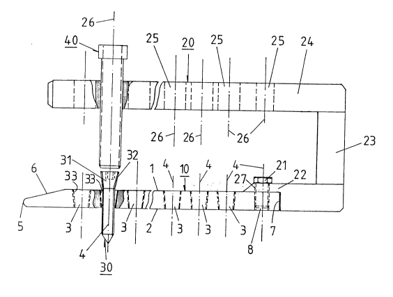
Referring to Fig. l, an osteosynthetic bone plate 10
according to the invention has an upper surface 1, a lower
surface 2, and several screw holes 3 connecting the upper surface
1 with the lower surface 2, which serve to receive bone screws
30. The plate has a first end 5 and a second end 7. The first
plate end 5 has a bevel 6 at the upper surface, like the point of
a flatiron, so that when plate 10 is inserted through soft
tissue, the lowest possible resistance, and thus the minimum
degree of injury, occurs. For this purpose, the side walls 9 of
the plate can also taper slightly to a point. The second end 7
of the plate has coupling means in the shape of a cylindrical
threaded hole 8 by which an insertion device 20 can be fastened
in a detachable manner by means of a fastening screw 21.
The screw holes 3 are conically shaped, tapering in the
direction of lower surface 2, and are provided with internal
threads 33 which correspond to the external threads 32 of the
bone screws 30 which they are to receive. In this way, an
absolutely rigid connection is achieved between plate 10 and
screws 30, which is of utmost importance. The conical angle is
advantageously between 2.0 and 4.0, preferably between 2.5 and
3.5. Especially preferred is a conical angle of 3.
The flatiron shaped insertion device 20 has at its end 22 a
cylindrical hole 27 for coupling with plate 10. A fastening
screw 21 can be guided through this hole in order to temporarily
attach the insertion dev~ce 20 to the plate 10. A
perpendicularly arranged spacer element 23 is attached at end 22,
2~ 75~ ~
and connects the end 22 to a guide handle 24. The handle 24,
when the guide 20 is joined to the plate 10 is parallel to plate
10. Handle 24 has cylindrical holes 25, whose axes 26 align
exactly with axes 4 of the plate holes 3. In this way it is
possible, by means of suitable instruments such as drill guide 40
(and also drills, length measuring devices, setting instruments,
etc., not shown~, to insert screws 30 through coaxial holes 3 and
25, and to fasten the screws to the bone, rapidly and precisely,
without an X-ray apparatus. The coupling and uncoupling of
insertion device 20, by means of fastening screw 21, is
accomplished through the corresponding hole 25 in guide handle
24, which aligns with hole 8 in plate 10, the hole 25 being of
sufficient diameter to permit removal of screw 21.
The dimensions of plate 10 depend largely on the bone being
set, or the fracture being treated. For use on the tibia, the
width of the plate is about 12 mm, the height of the plate about
4 mm, and the length of the plate between 200 and 300 mm. For
use on the femur, these dimensions would be somewhat larger.
Spacer element 23 is about 50 mm long when used on the
tibia, or about 100 mm long when used on the femur.
Figure 2 represents the emplacement of a plate 10, according
to the invention, implanted to bridge a fracture 51 of the tibia
50; insertion device 20 is still attached, and projects out
through incision 52. ~late 10 is fastened to the bone with three
screws located proximally to fracture 51 and three screws, such
as 30, located distally to ~t, in such a way that a space 53
-- 8 --
remains between bone 50 and plate 10, which permits
revascularization.
Figure 3 represents the emplacement of a plate 10 according
to the invention, to bridge a fracture 61 of femur 60. Here the
insertion device used (not shown) has already been removed
through incision 62. Just as is illustrated in Figure 2, the
individual fragments 61 are not themselves fastened, in
this operating technique~ but are bridged over by plate 10.
In addition to the advantages discussed above further
advantages are achieved by the invention as follows:
- The osteosynthetic plate can be used as a bridging plate,
so that the fracture need not be 100% repositioned.
- The osteosynthetic plate need not be adapted to the
anatomy of the bone being treated.
- The implantation is performed through a minimal incision
some distance from the fracture. This minimizes any additional
disturbance of the biology around the fracture. The cosmetic
advantage of a far shorter scar is appreciable.
- Simple, controlled insertion of the flatiron-shaped plate
is made possible by the guide handle.
- The drilling, of holes in the bone, tapping of such holes,
length measurement and setting of bone screws can be done in a
planned manner by means of the guide handle.
- Owing to the firm anchoring of the screw heads in the bore
holes of the plate, the plate can be positioned away from the
surface of the bone, which is of extreme importance for
maintaining the blood perfusion of the bone.
~7 ~
- Since the anchorinq of the screws is necessary only in the
near cortex, the range of screws needed can be reduced to about 3
screws per system dimension.
- The screws engaged in only one side of the cortex can have
a self-cutting point, since they come to rest in the medulla.
There can be no damage to the soft tissue due to a self-cutting
screw point.
-- 10 --