Note: Descriptions are shown in the official language in which they were submitted.
20~ 7~8~
HYDRAULICALLY SET ANCHOR
FOR WELL TOOLS
Background O~ The Invention
I. Field of the Invention
This inve~tion relates to anchors for setting well
tools in a well and, in particular, to a hydraulically set
anchor for use in a whipstock assembly to provide su~icient
anchorage to facilitate kick-o~ from the primary well bore.
II. Description of the Prior Art
Packers and anchors are typically used in well bores to,
seal of~ sections of a well and/or to provide support
structure for well tools in the production process.
Deviating tools, whipstocks, perforating tools, etc. are
examples of tools which employ an anchor or packer. In many
instances, the anchor/packer is run ~nto the well and set
with one trip of the running string and the particular
device engaged with the anchor/packer using a second trip of
the running string. With the tool supported against the
anchor/p~cker, the particular operation can be conducted.
More recently, in order to reduce production costs, the
tool has been combined with the anchor/pacXer thereby
eliminating one trip of the running string. Consequently,
the anchor/packer is set in the well using mechanical or
hydraulic means extending t rough the well tool a~ter which
the tool is engaged to carry out the operation. Once the
operation is completed the anchor/packer is typically
abandoned with the well.
In the prior known hydraulically set anchor/packer, the
hydraulic pressure may have to be maintained in order to
prevent release o~ the tool. As a result, mechanically set
tools are typically used in one-trip combination assemblies
........
72290 28
2 ~ 4 ~
since the mechanical set can be maintained following
disconnection of the production tool. However, mechanically
set anchor/packers are unreliable in high pressure wells because
of the extreme setting forces required which cannot be achieved
in such tools. Moreover, it has been found that in many appli-
cations, the well bore does not need to be sealed off by packing
elements.
Summar~_of the Present Invention
The present invention overcomes the disadvantages of
the prior known setting tools by providing a hydraulically set
anchor which can be attached to various well tools to provide a
supporting surface for continued operations. The anchor of the
present invention is adapted to be securely set in the cased well
under a minimum of hydraulic pressure as a result of the shallow
angle between the slip cones and the associated slip elements.
This invention relates to an anchor for well tools,
said anchor being hydraulically set within a cased well bore
using hydraulic fluid supplied to the anchor through a well tool,
said anchor comprising: an inner mandrel having a fluid passage-
way selectively communicating with the hydraulic fluid supply;a piston cylinder in fluid communication with said fluid passage-
way of said mandrel, said cylinder having piston means slidably
disposed therein; a slip assembly mounted to said mandrel, said
slip assembly including at least one movable slip cone and a
plurality of slip elements selectively expandable into anchoring
engagement with the cased well bore upon movement of said at least
one movable slip cone, said at least one movable slip cone
movable in response to extension of said piston means within said
72290-28
20~7~8~
cylinder; and interlock means for preventing retrac~ion of said
slip elements from the cased well bore.
This invention further relates to a whipstock assembly
for changing the direction of drilling through a cased well bore
comprising: a running tool for positioning said whipstock
assembly in the cased well bore, said running tool having a fluid
passageway; a whipstock connected to said running tool; a
hydraulically set anchor connected to said whipstock, said anchor
including a fluid passageway, a hydraulically set slip assembly
and interlock means for preventing retraction of said slip
assembly; and fluid passage means for supplying hydraulic Eluid
from said running tool to said fluid passageway of said anchor.
The h~draulically set anchor of the present invention
includes an adapter sub for connection to the production tool
and which is joined to a mandrel having a partial axial bore
forming a fluid passageway. The fluid passageway communicates
with a cylinder formed by the annulus surrounding the mandrel
within which is movably disposed a piston assembly. The piston
assembly engages the movable upper slip cone of the anchoring
slip assembly. The lower slip cone is stationary and is secured
to the lower end sub of the anchor. The slip elements are
circumferentially spaced and extend between the movable upper
slip cone and the lower slip cone. The shallow angle between
the slips and the slip cones facilitates secure engagement of the
slip with the casing. The forces generated by the hydraulic
pressure acting on the inner piston of the tool creates a higher
setting orce which cannot be achieved by prior known mechanically
set anchors. Moreover, the
2a
20~7~8
mechanical ~orce required to shear the bolts of the tool
adds to the hydraulic force to set the anchor.
An interlock assembly maintains the set position of the
slip assembly with respeGt to the casing. In the preferred
embodiments, the interlock assembly is associated with the
movable upper slip cone and the mandrel such that as the
upper slip cone travels along the mandrel the position will
be maintained therealong. Accordingly, the slip assembly
can be locked at any position facilitating anchoring to
various casing diameters.
Other objects, features and advantages o~ the invention
will be apparent from the following detailed description
taken in connection with the accompanying drawings.
Brief Description Of The Drawinqs
The present invention will be more fully understood by
referenc~ to the following detailed description of a
preferred embodiment of the present invention when read in
conjunction with the accompanying drawing, in which like
reference characters refer to like parts throughout the
views and in which:
FIGURE 1 is a cross-sectional perspective of a first
embodiment of the anchor of the present invention as it is
run into the cased well bore;
FIGURE 2 is a cross-sectional perspective of the first
anchor set within a well casing, the anchor being shown set
in two di~ferent diameter casings;
FIGURE 3 is an enlarged perspective of the interlock
assembly o~ the first embodiment of the present invention;
FIGURE 4 is an enlarged perspective of the interlock
assembly of a second embodiment of the present invention;
FIGURE 5 is a cross~sectional perspective of a second
emhodiment of the anchor of the present invention;
2~1~7~8
FIGURE 6 is a cross-sectional view of a well bore with
a whipstock assembly incorporating the anchor of the present
invention being run into the well; and
FIGURE 7 is a cross-sectional view of a well bore with
a whipstock assembly set therein using the anchor of the
present invention.
Detailed Description Of A Pref rred
Embodiment Of The Present Invention
Referring to the drawings, there are shown preferred
embodiments of a hydraulically set anchor 10 adapted to be
set within a cased well bore 12 for anchoring various well
tools including whipstocks for kicking off in a different;
direction from the well bore 12 (~igs. 6 and 7). The anchor
10 may be run into the cased well bore 12 in conjunction
with the well tool for single trip operations or may be
separately run into the hole using a running tool. The
whipstock may be attached to a mill, a bit or a separate
running tool. The construction and con~iguration of the
anchor 10 facilitates secure setting thereof under hydraulic
fluid pressure supplied to the anchor 10 as will be
subsequently described.
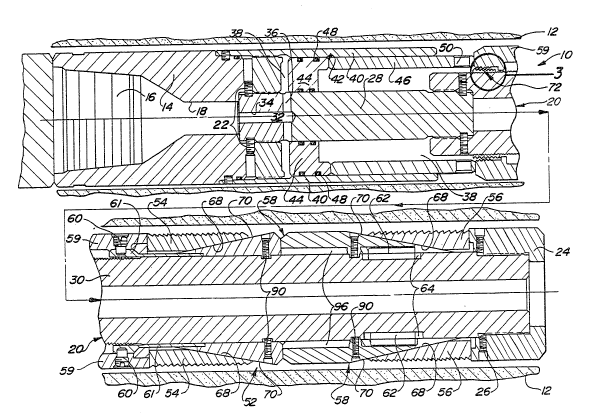
Referring now to the embodiment of Figures 1 through 3,
the anchor 10 is adapted to be selectively connected to a
well tool, such as a whipstoc~ or running tool, using an
adapter sub 14 having a box connection 16. The sub 14
includes an axial fluid passageway 18 through which the
hydraulic setting fluid is supplied. Matingly received by
and connected to the sub 14 is an inner mandrel 20 which
extends substantially the length of the anchor 10. The
mandrel 20 is connected to the adapter sub by a threaded
connection 22. The downhole end of the mandrel 20 is
connected to a nose sub 24 by threaded connection 26. In
thiS embodiment, the nose sub 24 forms a part of the lower
2~47~8~
slip cone although the sub 24 may be form~d ssparately from
the lower slip cone as shown in Figure 5. In a preferred
embodiment, the mandrel ~0 comprises an upper section 28 and
a lower section 30 although the mandrel 20 may be integrally
~ormed.
The mandrel 20 includes a fluid passageway 32 formed by
a partial axial bore 34 and a lateral bore 36 to supply
hydraulic fluid to a piston cylinder 38. The cylinder 38
comprises an annulus formed around the mandrel 20 and within
an outer wall 40 which extends from the adapter sub 14.
Accordingly, the adapter sub 14 forms the uphole end of the
cylinder 38 while the downhole end of the cylinder 38 is
open to allow a piston assembly 42 to extend from within the~
cylinder 38. The piston assembly 42 also has an annular
configuration and is slidably received within the cylinder
38. Movement of the piston assembly 42 is affected by
increased hydraulic pressure within the cylinder 38 uphole
of piston assembly 42 which is supplied through the fluid
passageway 32 as will be subsequently described. The piston
assembly 42 preferably includes an annular piston head 44
sealingly recPived within the cylinder 38 so as to be
affected by the hydraulic pressure and a piston rod 46
extending from the piston head 44. 0 ring seals 4~ carried
by the piston head 44 prevent fluid leakage past the piston
assembly 42. In a preferred embodiment, the piston rod 46
abuts against the piston head 44 and is thereby affected by
the sliding movement of the piston head 44. However/ the
piston rod 46 may be secured to or integrally formed with
the piston head 44. The downhole end of the piston rod 46
preferably includes a port 50 to allow fluid flow within the
chamber 38 to flow therefrom as the piston assembly 42 moves
within the chamber 38.
The downhole end of the piston rod 46 engages a slip
assembly 52 of the anchor 10, specifically upper slip
~7~
elements 54 of the slip assembly 52. The slip assembly 52
is mounted to the mandrel 20 and also includes lower slip
elements 56 and a double slip cone 58. In a preferred
embodiment, the upper slip elements 54 are movable in
response to extension of the piston rod 46 thereby driving
the slip elements 54 radially outwaxdly into anchoring
engagement with the casing 12. Ths upper 51ip elements 54
are initially locked against movement by shear screws 60
extending through a housing locking nut 59 into a locking
sleeve 61 mounted to the mandrel 20 thereby preventing
travel of the upper slip elements 54 until a predetermined
hydraulic pressure is a~tained. In a first embodiment, an
anti-rotation key 62 is disposed between the slip cone 58
and the mandrel 20. The key 62 is received within
longitudinal slots 64 in the mandrel 2~ to prevent rotation
of the slip assembly 52 relative to the mandrel 20.
The movable slip elements 54 and the fixed lower slip
elements 56 include interface surfaces 68 which cooperate
with the sloped surfaces 70 of the slip cone 52 to drive the
elements radially outwardly. The shallow angle of the
interface surfaces 68 facilitates secure setting of the slip
assembly 52 under a minimum of hydraulic fluid pressure. -In
a preferred Pmbodiment, the slope of the interface surfaces
68 is less than 20 degrees and preferably 10 degrees. As a
result, a simple slip assembly utilizing a single movable
slip cone is sufficient to securely anchor the device.
Moreover, the shallow slope of the interface allows the
anchor 10 to be utilized in different casing diameters as
shown in Fig 2 where the anchor lO is set in two different
casings 12.
Referring now to Fig. 1-3, as the 51ip assembly 52 is
set, interlock means 72 are provided to prevent retraction
of the upper elements cone 54 and release of the slip
assembly 52 once hydraulic pressure is reduced or
204~8
eliminated. As best shown in Fig. 3, the interlock means 72
comprises a locking nut 74 having a first ratchet surface 76
which cooperates with a ratchet surface 78 on the lockiny
housing 59 and a second ratchet surface 80 which cooperates
with a ratchet sur~ace 82 on the mandrel 20. Th~ mandrel
ratchet surface 82 extends a substantial length beneath the
locking housing 59 such that contact is maintained between
the locking nut 74 and the mandrel 20 as the locking housing
59 and the upper slip elements 54 moves towards the slip
cone 5~. The ratchet sur~aces are con~igured to allow
movement of the locking housing 59 and the upper slip
elements 54 in a first downhole direction but prevent
movement in a second direction. The ratchet surfaces 80 and
82 have smaller teeth to facilitate movement in the ~irst
direction while the teeth of the ratchet surfaces 76 and 78
are larger to allow movement only under extreme pressures.
Accordingly, once the slip assembly 52 has been set, the
hydraulic pressur can be eliminated and the well tool
detached without causing release of the slip assemblyO The
position of the double slip cone 58 is maintained through a
series of shear screws 90 which extend into the mandrel 200
The slip cone 58 includes an upper cone section 92 and a
lower cone section 94 which cooperate with the upper slips
54 and lower slips 56, respectively. The lower cone section
94 prsferably includes at least one spline or keyway 96 to
allow the cone 58 to travel longitudinally along the key 62
in order to expand the lower slip elements 56 into
engagement with the casing 12. The shear screws 90 are
designed to shear prior to screws 60 such that upper slip
elements 54 and the double cone 58 will move longitudinally
to set the lower slip elements 56 prior to setting the upper
elements 54. The sleeve 61 prevents setting of the upper
elements 54 until screw 60 i5 sheared.
2~7~8~
In a second embodiment of the anchor 10 shown in
Figures 4 and 5, operation is substantially identical to the
first embodiment although the construction of the anchor 10
is slightly different. As shown in Fig. 5, a fixed lower
slip cone 156 is a separate component from a nose sub 124.
Furthermore, the anti-rotation key 162 is associated with a
lower slip cone 156 and seats within the shorter 510t 164 in
the mandrel 20. The interlock means 172 is also slightly
different as shown in Fig. 4. As with the ~irst embodiment,
the interlock means 172 comprises a locking ring 174 with
first and second ratchet surfaces. However, the shear
screws 160 are provided with a spacer 190 having a ratchet
surface 192 which cooperates with the ratchet surface 178 of;
the upper slip cone 154. Accordingly, the shear screws 160
extend through the interlock means.
Operation of the hydraulically set anchor 10 within a
cased well bore 12 is identical for both embodiments of the
anchor 10. With the anchor 10 connected to a well tool such
as a simple running tool or a whipstock through the sub 14,
hydraulic fluid pressure is supplied through the passageway
18 of the sub 14 and the passageway 32 of the mandrel 20.
The increased fluid pressure within the piston cylinder 38
will exert a downward ~orce on the piston head 42. At a
predetermined pressure, the screws 90 will shear releasing
the slip cone 58 from the mandrel 20 and allowing the piston
assembly 42 to move the slip cone 58 in the first downhole
direction. Once the lower elements 56 are set, the screw 60
will shear allowing the upper elements 54 to set and freeing
the locking housing 5g. ~s this occurs, the second ratchets
of the locking nut 74 will move across the ratchet
surface 82 of the mandrel 20. As the upper slip elements 54
move towards the fixed lower slip elements 56, the slip
elements will expand outwardly until the teeth of the slip
elements are imbedded into the casing 12 anchoring the
2~47~88
device therein. As is shown in Fig. 2, the anchor 10 may be
utilized in different diameter casings 12 with only the
degree of downhole movement of the upper slip elements 54
changing. With the slip assembly 52 set into the casing 12
the hydraulic pressure may be eliminated. The interlock
means 72 will prevent the upper slip elements 54 from moving
in the second uphole direction thereby preventing release of
the anchor 10. Thus, the present invention provides a
hydraulically set anchor 10 which provides secure anchoring
for secondary well tools.
As an example of an application of the anchor 10,
Figures 6 and 7 show the anchor 10 incorporated into a
whipstock assembly 100 for directional drilling. In theL
embodim~nt shown in the drawings, the anchor 10 is secured
to the lower end of the whipstock 100 which in turn is
connected to a running s~ring 102. The running string 102
is used to position the whipstock 100 as well as supply the
fluid pressure required to set the anchor 10. A fluid
passageway 104 through the running string 102 and the
whipstock 100 communicates with the axial passageway 18 of
the anchor 10. Once the anchor 10 has been set to se~ure
the whipstock 100 the running string 102 is disconnect2d
form the whipstock 100 to allow a mill 106 or other cutting
tool to be run into the hole for ~-utting through the casing
108. However, upon disconnection of the running sting 102
the hydraulic pressure from above will be cut of~ causing
the prior known anchors to release. The interlock means 72
of the present invention prevents disengagement of the
anchor 10. Thus~ the anchor 10 and whipstock 100 will
remain set in the casing 108 allowing the necessary milling
operation.
In addition to running the whipstock 100 into the hole
using a string 102, the whipstock 100 may be attached
directly to the mill 106 resulting in a single trip
2 ~
operation. The anchor 10 could also be run and set
independently for other operations although the
hydraulically set anchor 10 lends itself for use with a
whipstock 100 since orientation of the whipstoc~ within the
casing 108 is crucial. The prior known mechanic~lly set
anchors re~uired rotation of the string causing the offset
surface of the whipstoc~ to become disorientated from the
desired placement. Moreover, it was previously believed
that only packers could be used in such operations because
of the pressure compensation properties of the packing
elements. However, the present invention provides an anchor
10 which can be positively and securely set within a casing
using hydraulic pressure. The shallow angles of the 51ip~
elements and slip cones allows secure engagement with the
casing under reasonably attainable hydraulic pressures.
The foregoing detailed description has been given for
clearness of understanding only and no unnecessary
limitations should be understood there~rom as some
modifications will be obvious to those s~illed in the art
without departing from the scope and spirit of the appended
claims~
What is claimed is: