Note: Descriptions are shown in the official language in which they were submitted.
2~763~
FIELD OF THE INVENTION
This invention relates to Magnetically Impelled Arc
Butt welding (or "MIAB" welding") for joining pipes. This
invention is particularly suitable for joining large
diameter pipes (having a diameter greater than 150mm).
BACRGROUND OF THE INVENTION
MIAB is well established for joining thin wall tubular
sections of thickness less than 1 mm and diameter less than
30 mm in mild steel, such as for low pressure pipe
connections. Also this process has been used for thicker
wall hollow sections up to 4 mm thickness for pipes and
tubes of some 50 mm diameter. The MIAB technique has been
extended to thicker wall pipes by orbiting one end with
respect to the other in order to enable the arc to seep
across the entire cross-section of the faying surfaces.
This technique has been used for welding thick walled pipes
of up to 8 mm wall thickness and 150 mm diameter. Such
cross-sections, however, can only be welded successfully by
the orbiting technique and not by the conventional process,
where the opposing ends are held co-axial with each other.
Examples of MIAB welding machines are disclosed in U.S.
patent 3,882,299 (Sciaky); 3,937,916 (Sciaky); 3,980,857
(Sciaky); 4,136,980 (Pache et al); 4,319,123 (Pache et al);
4,443,686 Pache et al); 4,273,986 (Edson et al); 4,219,722
(Rudd et al); and 4,246,464 (Altsetter et al).
2 --
2047638
Prior MIAB welding machines have been proposed for both
shop work (i.e. a fixed-in-place machine~ and field work
(i.e. a portable machine. In general, the portable machines
of the prior art are designed to be lowered onto the pipes
being welded and hence have clamping systems which open and
close at a position below the pipes being welded together.
Thus, when a weld is completed, the clamps are disengaged
and the MIAB welding machine is lifted off of the pipes.
Such machines have an inherent safety disadvantage when used
with large diameter pipe, namely that it is necessary to
observe the underside of the pipe in order to determine
whether the clamping means are properly engaged (thus
exposing the observer to the risk of injury if the pipe
falls out of the machine or if the machine slips from its
support).
Accordingly, it is an object of this invention to
provide a portable MIAB machine in which the clamping means
are operable so that the pipe may be lowered into the
machine (i.e. as opposed to having the machine lowered onto
the pipe).
MIAB welding typically produces a characteristic weld
"upset" along the weld line (i.e. the "upset" is a ridge of
metal, resulting from the application of forging pressure to
the abutting ends of the pipes during the welding
procedure). As this upset represents lost pipe material
(and as this loss may be significant during the construction
20~76~8
of a long pipeline), it is desirable to minimize it.
Accordingly, it is another object of this invention to
provide a MIAB welding process in which this weld upset is
monitored.
~UMMARY OF THB INVENTION
In one embodiment of the invention, there is
provided: a portable magnetically impelled arc butt welding
apparatus for welding a joint between the adjacent ends of
two pipes, said apparatus having a housing, a magnetically
impelled electric arc welding head disposed outside of said
pipes, first pipe clamping means and second pipe clamping
means which are movably attached to said housing, wherein
said first pipe clamping means and said second pipe clamping
means are operable so as to receive said pipes from above
said housing.
In another embodiment of the invention, there is
provided: a method for magnetically impelled arc butt
welding apparatus for welding a joint between the adjacent
ends of two pipes, said method consisting of (a) clamping a
first pipe with first clamping means, (b) establishing a
zero datum condition by clamping a second pipe with second
clamping means and positioning said second pipe in close
proximity to said first pipe so as to establish a small gap
between said pipes; (c~ generating a first signal
corresponding said zero datum conditions and transmitting
said first signal to a programmable controller; (d)
20~7638
establishing a magnetic field within said gap; (e) striking
a welding arc between said pipes; (f) actuating a
hydraulically driven forge so as to apply a forging pressure
along the axial lengthwise direction of said pipes such that
said pipes are forged together; (g) monitoring the movement
of said pipes during the application of said forging
pressure; and (h) generating a second signal corresponding
to the movement of said pipes and transmitting said second
signal to said programmable controller.
BRIEF DE8CRIPTION OF THE DRAWINGS
Embodiments of the invention will now be described in
detail by way of example with reference to the non-limiting
drawings, in which:
Figure 1 is an isometric view of an apparatus according to
the invention.
Figures 2, 3 and 4 are views of electromagnetic systems
which may be employed in this invention.
Figure 5 is a view of a permanent magnet system which may be
employed in this invention.
Figure 6 is a sectional view of a pipe clamp having a
castellated profile.
Figure 7 is an end view showing the clamps of a four
clamping component pipe clamping system.
Figure 8 is an end view of a pipe clamping system having a
positive engagement point located above the pipes.
Figure 9 is an end view of an alternative pipe clamping
20~7~38
system having a positive engagement point located above
the pipes.
The MIAB process relies on the principle of
establishing a magnetic field or a component thereof, at
right angles to the path of the current in the arc, so that
motion is obtained in the third axis. This motion is
applied to the current carrying conductor, in this case an
electrical arc. With a suitably arranged radial field, the
arc can be made to travel in a circular direction, as shown.
Thus, in the case of circularly symmetrical components, such
as pipes or tubes, and with the components separated a short
distance and supporting an electric arc between them, then
the application of a radial field (i.e. with respect to the
circular components) will cause the arc to rotate around the
abutting or adjacent faces of such tubes.
As commonly practised, the MIAB equipment as used for
joining pipes of relatively thin wall and small diameter is
equipped with electro-magnetic coils which generate
longitudinal magnetic flux in the pipes such that the
opposing faces are of the same magnetic polarity giving rise
to a divergent and particularly a radial field in the
vicinity of the gap between the opposing pipe ends. Then
with an arc struck between the two components and with a
sufficient field strength and arc current, the arc is forced
to move in the circum~erential direction and rotate around
the pipe axis between the abutting ends. However, in the
20~7638
intended application to pipelines and the like, it is
inconvenient to use solenoid type magnetic coils, which have
to be wound around the pipe. Thus, the magnet system is
arranged such that a pipe component, particularly of
extensive length, can be withdrawn laterally from the
apparatus. In particular, for use as in pipeline laying, it
is convenient to have a self-contained apparatus, which
provides not only for lateral access and removal from the
pipe system, but also for aligning a further pipe section to
an existing pipeline, without relying on reference to ground
levels and the like.
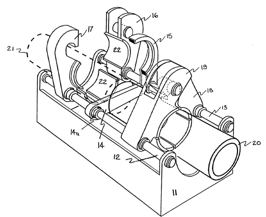
One example of an apparatus, according to the
invention, is shown in Figure 1, where the overall machine
(10) comprises clamping means for attachment to the circular
pipe (20), together with means for aligning a further pipe
section (21), to be butted against the existing pipe. Thus,
according to the invention, a housing (11) i5 provided, for
example with tie bars (12, 13) on which are mounted both
clamping means (16, 17 together with 18, 19) for holding the
existing pipe (20) and the additional pipe (21) in alignment
one with the other.
As will be apparent from Figure 1, the clamping means
(16, 17, 18 and 19) open in an upwards direction so as to
receive the new piece of pipe to be joined from above. That
is, the clamping means are open towards the sky. This
configuration is different from conventional portable MIAB
20A7638
machines which are lowered onto the pipes (and hence these
machines open in a downwards direction welding, so as to
receive the pipes from below). The present MIAB welding
apparatus provides a safety feature in that it is possible
to readily establish by visual observation from above
whether the clamping means are properly engaged. In
contrast, the conventional configuration of portable MIAB
welding machines typically request a worker to crawl
underneath the machine to determine whether the clamping
means are engaged.
For aligning the existing pipe (20~ with respect to the
machine housing (11), a pipe positioning bar (14) is
positioned as shown in Figure 1, and the end of pipe (20) is
butted against the positioning bar (14) prior to closing the
clamps (18, 19). The pipe positioning bar (14) is pivotally
attached to the housing (11) via tie bar (12). The pivotal
attachment joint (14a) is fixed with respect to the
lengthwise axis of the housing (11) (i.e. the pivotal
attachment joint does not move along the length of the tie
bar (12)). Pipe component (21) is brought into close
proximity to existing pipe (20), so that the adjacent ends
of the two pipes form a small gap. Thus, the position of
this gap is fixed with respect to the lengthwise axis of the
housing (11) by the pipe positioning bar (14).
As shown in Figure 1, the magnet system (15) is
pivotally attached to the housing (11) via the tie bar (13),
8 --
2047538
but the pivot point position of the magnet system (15) is
fixed with respect to the lengthwise axis of the housing
(ll) (i.e. the magnet system (15) does not move long the
length of the tie bar (13)). (A more detailed description of
the clamping system is given with respect to Figures 8 and 9
below).
Having clamped the machine with respect to the first
pipe (20) the pipe positioning bar (14) is removed and the
additional pipe (21) brought up to butt pipe (20) and held
in position by clamps (16, 17). In operation, the pipe
component (21) is separated from the pipe (20) a short
distance during the arcing stage and then is subsequently
butted firmly against pipe (20) to complete the forge weld.
For convenience of presentation the actuating rams for the
clamps (16, 17, 18, and 19) are not shown, nor the means for
the longitudinal movement, where at least one pair of clamps
are moved with respect to the other axially, along of the
tie bars (12, 13). In addition, means are not shown for
removing the pipe positioning bar (14) out of the system,
nor for inserting the magnet system (15) into proximity with
the circular pipe in order to obtain the required arc
rotation about the pipe end. It should be noted that by
means of the housing (11) and associated tie bars (12, 13)
the apparatus is aligned with respect to one pipe component
and allows for a second pipe component to be aligned with
the first. The housing (11) preferably contains all the
2047G38
required actuators and connectors providin~ hydraulic
control of the actuating rams.
For large diameter pipes, it is especially preferred to
employ a hydraulic fluid accumulator (not shown) in the
hydraulic system used to actuate the opening and closing of
the clamps. In the absence of such an accumulator, the
apparatus may be prone to excessive vibrations during
transient conditions (As used herein, the term "hydraulic
fluid accumulator" is meant to refer to its conventional
meaning, namely a device which is used for surge control in
high volume flow hydraulic systems. Such accumulators
normally consist of a shell having a generally cylindrical
shape, and a pressurized bladder contained within the shell.
The bladder is fabricated from a flexible material (e.g.
nitrile rubber) and is precharged with a compressible gas
(i.e. nitrogen) to a pressure suitable for the system. When
the hydraulic pump in the system forces hydraulic fluid into
the accumulator, the gas in the bladder is compressed, and
the pressure in the bladder this increases. The
deformation/compression of the bladder ceases when the
pressure of the hydraulic fluid balances the pressure of the
gas within the bladder. When there is a subsequent demand
for the hydraulic fluid, the pressure in the system is
reduced and the hydraulic fluid flows into the system under
the pressure exerted by the compressed gas in the bladder.
such "accumulators" are well known and are commercially
-- 10 --
2~47~38
available from sources including tOil Air Hydraulics Inc. of
Houston, Texas).
As previously noted, at least one pair of clamps is
movable with respect to the other axially, along the tie
bars. This axial movement provides the foregoing force
requirement to complete the weld. It is preferred that only
one pair of the clamps move in the axial direction, so as to
minimize the number of operations which must be controlled.
Furthermore, it is highly preferred that the hydraulic
system used to actuating the above described forging force
also contains a hydraulic fluid accumulator.
As will be appreciated, the complete welding apparatus
is self-contained and can be readily manipulated or slung
from, for example, a crane into the desired position with
respect to the pipe or pipeline. It is also noted that the
butting force for forging the pipe component (21) onto the
existing pipe (20) is obtained via the clamping system and
does not rely on an end stop or end longitudinal actuator
attached to the extremity of the pipe.
MIAB welding requires both of a magnet system and an
electric arc system. Accordingly, the term "welding head"
used herein is mean to include the combination of the magnet
system and the electric arc system. Details regarding the
electric arc system and magnet system are given below.
It is preferred to provide an electric arc by simply
passing a current through the clamps (16, 17, 18, and 19).
-- 11 --
2047638
This can be readily accomplished by fabricating the clamps
from an electrically conducting material (such as a ferritic
material) and wiring each of them to an electrical source
(not shown). It is especially preferred that the wires used
for this purpose arc have substantially the same electrical
resistance and are connected in parallel to a common
electrical power supply, so that an essentially equivalent
current is applied to each clamp.
The clamps (16, 17, 18 and 19) are provided with
circular faces (22), such that the internal clamping
surfaces are curved so as to substantially match the
curvature of the outer surface of the circular components
and which when closed provide substantially continuous
contact with the exterior of the pipe with only small gaps
(23) between the faces of the jaws (22) as shown in Figure
7.
Preferably the magnetic field is applied in the form of
a doughnut shape surrounding the pipe, as generated by a
series of permanent magnets or electro-magnets polarised to
present a face with a single polarity surrounding the pipe
concerned. Preferably the permanent magnets or electro-
magnets are associated with the clamping means such as via
the tie bars (12, 13) so as to surround the pipe at a
nominally constant distance from the pipe surface.
Conveniently, with four clamps surrounding the pipe the
corresponding magnet systems provide substantially a
- 12 -
2047638
continuous magnetie pole surrounding the pipe. The return
magnetic circuit via the pipe eomponents and the surrounding
apparatus of ferritic material may be supplemented by
ferritic material embraeing the magnet or electro-magnet on
one or all sides apart from the side facing the pipe
exterior. It will be apparent from Figure 1 that the
welding head (i.e. the magnet system and the electrie are
system, eolleetively) are disposed outside of the pipes.
As illustrated in Figure 2 for use with large pipe
seetions in exeess of 150 mm diameter, especially those of
200 or even some 300 mm diameter, the magnet system (30)
preferably comprises a plurality of similar magnet blocks
(31) presenting a virtually eontinuous profile in terms of
field strength about the circumference of the section to be
butt welded. In partieular, the overall magnet system (30)
preferably, comprises 4 groups of eleetro-magnets with
preferably more than one eleetro-magnet (32) per quadrant.
Conveniently 2 or 3 electro-magnetic coils (32) exciting
corresponding eores (33) whieh are connected together via a
eommon pole piece (34) are eonneeted to a suitable
energising souree (not shown). The source may be of a
eommon potential and all the eleetro-magnet eoils paralleled
as they are of substantially the same resistance.
Alternatively, the groups of 2 or 3 coils may be eonneeted
in series and each set eonnected in parallel to a common
voltage souree. Again, alternatively, corresponding coils
- 13 -
2047638
from each quadrant may be connected in series and each set
of four such coils connected to a common voltage source.
These connections are a + b + c (or al + a2 + a3 + a4 and
so forth).
Conveniently, the magnetic pole facing the pipe
exterior may be covered with protective layer such as
stainless steel or copper sheet to avoid direct impingement
of spatter from the weld zone. Equally the magnet,
particularly in the case of a permanent magnet, may be
protected by a non-thermally conducting layer for thermal
insulation to avoid excessive temperature rise from the
heated pipe ends and the rotating arc. Moreover, suitable
heat sinks can be provided adjacent to the magnet to assist
in avoiding excessive temperature rise. A suitable magnetic
material for the permanent magnets is a polymer bonded rare
earth magnet metal. The term rare earth metal is meant to
convey its conventional meaning, namely the elements of the
Periodic Table which are also referred to Lanthanides
(especially Nd and Ce). These magnets are preferably glued
or bonded into the system with a polymeric adhesive. For
example, as shown in cross-section in Figure 3, the electro-
magnet (33, 34) is positioned at a short distance away from
the exterior of the component (20, 21) and arranged such
that the flux from the pole-piece is returned via the wall
of the component to the surrounding ferro-magnetic case (35,
36) of the electro-magnet. The internal face of the magnet
- 14 -
20~7638
system is covered with a suitable protective layer (38) to
prevent spatter adhering to the magnet or potentially
damaging the coils (32). The magnet system is carried on a
suitable arm (37) in association with the clamping mechanism
(not shown).
Preferably the aspect ratios of the magnet system
should be such that the face of the magnet is substantially
greater than the gap between the components to be joined and
preferably of dimension at least 3 times the gap width.
Furthermore, a substantial air gap is provided between the
magnet face and the exterior of the pipe being joined, such
as in excess of 5 mm and preferably in excess of 8 mm such
as lo mm. These dimensions define the two aspect ratios of
magnet width to gap width and magnet separation to wall
thickness of the pipe being joined. For example, the
dimensions given are suitable for pipe wall thicknesses of 3
mm to 5 mm, and gap widths up to 3 mm. Thus as shown in
Figure 4, the width (41) of the pole-piece in the axial
direction transverse to the abutting face (40) should exceed
at least 3 mm on either side of the gap. Preferably the
width (41) of the pole-piece should be of the order of 5 mm
on either side of the gap (40). Alternatively, the width
should be at least one wall thickness T on either side of
the gap and preferably of the order of l l/2 T on either
side.
Equally, the width of the magnetic circuit (42, 43) on
- 15 -
20~7638
either side of the centre pole-piece (41) should be about
half the width of the centre pole-piece to present a
substantially symmetrical magnetic circuit and avoid
magnetic saturation in the ferro-magnetic material.
Equally the separation (44) of the surface of the pole-
pieces from the surface of the components to be joined
should be of the same order as the width (41) of the pole-
piece but preferably less, such as between 50% and 80~ of
the width. Alternatively, the separation (44) should exceed
the wall thickness T of the components (20, 21) to be joined
preferably is in the range of 2T to 3T. In all cases the
dimension (44) should preferably not exceed the dimension
(41).
For permanent magnets as shown in Figure 5, the
principal dimensions in the vicinity of the gap (40) are
similar to those for the electro-magnet but in general a
return circuit such as provided by the cheeks (35) of the
electro-magnet are not required. Preferably, the permanent
magnet (50) is mounted on a support (51) which is carried on
a suitable arm (52). These latter are of ferro-magnetic
material and can be proportioned to adjust the strength of
the field in the region of the position of the gap (40)
which is spaced at the distance (44) from the surface of the
permanent magnet material.
In the case of polymer bonded rare earth magnets, the
magnet material is preferably surrounded on either side and
- 16 -
2047638
on the face nearest the component to be joined with
thermally insulating material (53) to avoid the effects of
radiated and convected heat from the magnetically impelled
arc. Also the thermal insulation on the front face is
particularly required to reduce the effects of radiation
from the heated welded component. In addition to the
thermal insulation (53), preferably a further layer (54) of
material is used to limit or prevent the adherence of
spatter from the arcing process. The material (54) may be a
high thermal conductivity, such as copper or a temperature
resisting material such as stainless steel.
For electro-magnets in place of the permanent magnets,
preferably more than one excitation coil is provided on a
suitable core to provide a sufficiently uniform excitation
of the pole face. For example, with four magnet units
embracing nominally 90 of the periphery, each unit can
comprise two or more cores with exciting coils on each core.
For example, each individual electro-magnet coil may be
rated at some 2,500 ampere turns (2.5A with 1,000 turns) and
with 1 mm insulated copper wire the total voltage drop is of
the order of 10 V giving 25 watts per coil at 100% duty
cycle. For shorter duty cycles such as 1 in 10 or 1 in 20,
the power dissipated per coil can be significantly increased
without causing excessive temperature rise. The field
strength in the region of the position of the components to
be welded is preferably of the order of between 1,000 and
20~7638
2,000 gauss. For example, the field for a pipe of nominally
150 mm diameter is in the region of 1,400-1,600 gauss. The
field for a larger diameter component, such as in excess of
250 mm diameter, is preferably of the order of 1,600-1,800
gauss. In general it is convenient to increase the field
strength of the magnet system for larger diameters of
components in order to maintain an adequate rate of rotation
of the magnetically impelled arc at the preferred welding
current. Moreover, fields in excess of gauss have been
found suitable for welding pipe components of nominally 300
mm diameter.
Furthermore with both the permanent magnet and electro-
magnet pole design, gas ports can be provided to enable
suitable gas shields to be provided for the rotating arc to
prevent excessive oxidation of the heated surfaces of the
components being joined. Gaseous nitrogen is particularly
suitable for this purpose.
The segmented magnet system not only allows, in its
retracted position, for the pipe including the weld zone, to
be threaded through, but also for the pipe to be completely
detached from the welding head laterally out of the machine.
Accordingly, although the clamps open in an upwards
direction for safety reasons (and thus the welding head
can't be simply lifted off the pipes because a substantial
portion of the apparatus is below the new weld in the
pipes), the apparatus can be readily moved laterally along
- 18 -
20~7638
the pipeline to position it for the next weld.
The clamping system comprises a set of separate
segments preferably at least 4, with facing surfaces of
curvature matched to the pipe, within the limits of
variation of the pipe as produced. Furthermore, to obtain
an adequate grip, the internal surfaces of the clamps are
preferably serrated or provided with a castellated profile,
as illustrated, Figure 6. It is noted that the gripping
reacts a longitudinally applied thrust and that each part of
the serration is capable of elastically taking up a part of
the total thrust. The surface (22) of the clamp is of
relatively strong material, preferably with a yield strength
in excess of 30kg/mm2 so that it resists deformation and has
a sufficiently high elastic limit to allow thrusts of the
order of 200 kg per millimetre of periphery of the pipe.
Apart from the castellated profile, the internal surface of
the clamps is smooth and of a curvature substantially
matching that of the exterior of the pipe to avoid
significant surface indentation or distortion.
The clamps are arranged around the periphery of the
pipe such that the gap between the segmented clamps is, on
average, not more than about 3 mm and preferably at no stage
exceeds 1% of the total circumference. Thus, overall the
clamps surround the pipe to more than 95% of the
circumference. Figure 7 indicates the definition of the
overall degree of circumferential clamp. Thus with a
2047638
clamping system comprising four segments (22) for
surrounding the circular component (20, 21), the clamps are
brought together such that there is a finite gap (23)
between one clamp and the next. Preferably, the gap (23) is
of the order 1 mm for smallest diameter of component to be
gripped and does not exceed some 3 mm for the largest size
of circular component. Equally, preferably any one gap (23)
should not be zero or exceed some 5 mm. Where desirable,
means can be provided between the segments (22) to allow for
a more even distribution of the gap (23), such that the
clamping is substantially symmetrical and hence distortion
of a circular component is minimized.
The set of clamps can be relaxed sufficiently to allow
the pipe components to be threaded through, including the
weld zone. Furthermore, the clamping system opens in an
upwards direction so as to receive the pipe from above. In
other words, the welded pipe can be withdrawn laterally from
the clamp, and the new pipe can be inserted laterally or
from above.
In one arrangement with four operating and self-
aligning clamps with one degree of freedom, one pair are
arranged to interlock one with the other and the other pair
arranged to press the pipe into the arc formed by the co-
operatin~ pair, such that the pipe is substantially
completely surrounded. One example of a suitable clamping
arrangement is shown in Figure 8, in which the clamping
- 20 -
2~7638
mechanism (70) comprises two upper arms (71, 72) with pivots
(73, 74) fixed to the support plate (79) and two further
arms (75, 76) with pivots (77, 78) carried on actuators, not
shown, with a direction of movement at nominally 45 to the
vertical axis. To grip the pipe (20, 21) seen in end
elevation, the upper arm (72) is first closed in the
direction of the arrow (80), Figure 8a. Thereafter the co-
operating upper arm (71) is closed to interlock with the arm
(72~ such that the pin (82) on arm (72) falls within the
hoo~ (81) of arm (71), as illustrated in Figure 8b.
Thus, the pin (82) and hook (71) form a positive
engagement point that is located above the pipes. This is a
safety feature, as the operator of the apparatus is readily
able to visually determine that the clamps are engaged. (In
contrast, prior MIAB welding machines which are lowered onto
the pipes have a configuration which requires the clamps to
engage at a location below the pipe).
To complete the locking arm (72) is preferably moved in
the direction shown by the arrow (90) in order to present a
nominally hemispherical surface for the circular components
to be gripped via the faces (83, 84) on arms (71, 72)
respectively. Thereafter the arms (75, 76) are moved in the
direction shown in Figure 8c, at nominally 45 to the
vertical, as given by arrows (87, 88) such that the clamping
faces (85, 86) of arms (75, 76) locate the pipe and cause it
to be centred as shown with respect to the support plate
- 21 -
20~7638
(79). It is noted that arms (71, 72) effectively locate the
circular component in the transverse direction left or righ~
while the arms (75, 76) locate the circulate component in
the upward direction, in co-operation with arms (71, 72).
It is also noted that the clamping faces (83, 84, 85
and 86) virtually surround the circular component completely
with only small gaps between each nominal quadrant section.
These gaps are necessary to enable the circular component to
be rightly gripped when it is smaller in diameter than the
nominal size. To obtain a reasonable balance in the forces
applied by the actuators to the arms (77, 78) the actuators
are preferably hydraulically operated from a common
pressurised supply. As previously noted, the hydraulic
system used to operate the clamping system preferably
includes a hydraulic fluid accumulator, particularly when
the apparatus is used with large diameter pipes. In a
further alternative the upward pressing clamps may be
provided with more than one degree of freedom to allow for
self-alignment, as shown in Figure 9. Here a pair of pivots
are mounted on a common bridge, which in turn is pivoted.
Thus, as shown in Figure 9, the lower arms (75, 76) are
pivoted respectively at (77, 78) on bell cranks (91, 92).
These in turn, are pivoted at (93, 94) on a oommon swivel
(95) which is itself pivoted (96). Actuators as shown
operating on pivots (97, 98) move the bell cranks (91, 92)
in an upward direction so closing the arms (75, 76) around
22 -
2047638
the circular pipe (20, 21). The swivel (95) allows for a
degree of take-up between the two clamps (75, 76). Thus,
although the actuators operating on pivots (97, 98) may be
hydraulic rams, the further degree of freedom provided by
the swivel (95) allows direct mechanical actuators such as
screw jacks or cams, to operate on the ends of the bell
cranks (91, 92).
Also in Figure 9 is shown an alternative arrangement
for a positive engagement point of the upper clamp arms (71,
72). Here the clamp (71) is first closed in co-operation
with the arm (72) such that the hook (81) passes under the
pin (82). Again with outward movement of the arms (71
and/or 72) the pin (82) rests within the hook (81) and so
defines the location of the circular component in an upward
direction. Thereafter, the actuators on the bell cranks
(91, 92) bring the lower arms (75, 76) into position
encircling the pipe or circular component, as previously,
and locating it with respect to the support plate (79).
These and other arrangements providing for opening of the
clamping system and permitting complete withdrawal of the
component in a lateral direction are within the scope of the
invention as described.
For speed of operation hydraulically actuated clamps
are preferred, but other convenient means can be provided,
such as screw jacks or cam mechanisms.
Although, in principle, the MIAB process can be
- 23 -
2~47638
operated manually with butting and separating of the
components to be welded to initially form the arc and
thereafter with a suitable arc rotation and current level to
butt the components together, it is preferable for the
sequence of operations to be automatic to avoid error or any
undue variation in time intervals. Furthermore it is
preferable to monitor the sequence of operations and the
operating levels of current, gap between components, time
and (for electro-magnets) excitation current. This serves
as an internal quality control and quality assurance.
Although the complete operation of the machine can be
mechanised and supplemented with timers and the like,
preferably the control system utilizes both hardware and
software as appropriate, together with a suitable process
computer. Preferably facilities are provided for two or
more levels of arc current toqether with two or more levels
of operating gap between the components to be joined and in
the case of electro-magnets two or more levels of excitation
current. For example, suitable operating conditions for
nominally 12 in diameter pipe of 4.8 mm wall thickness are,
current 1600 amperes, excitation 30 amperes, gap 2 mm,
thrust (forge) 300 KNewtons and overall time 15 seconds.
In principle, the required applied load can be
registered using load cells and the like but preferably the
requisite loads are represented by pressure in the
appropriate hydraulic system. However, in some cases
2047638
pressure measuring devices need to be zeroed to overcome
effects of drift over long periods of time. Therefore,
preferably means are provided for registering zero operating
conditions, such as at retraction or before the forge load
is applied in hydraulic systems where the minimum pressure
is not necessarily zero itself.
Such means may be hardware or software orientated but
in principle detect the condition of non-operation and give
an appropriate zero register to the controller.
Further details concerning a novel method to
monitor/control a MIAB welding process are provided below.
As previously noted, it is desirable to establish zero
datum conditions corresponding to the position of the
clamped pipes, and the initial load on the hydraulic system,
prior to the welding/forging operations (i.e. there may be a
small load on the hydraulic system prior to the
welding/forging operations). It is highly preferred to
generate an electric signal corresponding to these zero
datum conditions, and to forward the signal to a
programmable logic controller ("PLC").
The welding/forging operations are then completed in
the manner previously described. However, the movement of
the pipes during the forging operation is also monitored.
In particular, it is desirable to monitor
(a) the distance travelled by the pipes, and
(b) the time elapsed during the forging operation,
- 25 -
20~763~
and to generate electric signals corresponding to (a) and
(b) above. By transmitting these signals to a properly
programmed PLC which PLC also contains data concerning the
zero datum conditions), it is possible to calculate
(a) weld upset (based on zero datum conditions
combined with data defining the distance of pipe
movement), and
(b) forge velocity (based on zero datum conditions,
combined with data concerning the distance of pipe
movement, and the time required for same).
As previously noted, it is desirable to monitor weld
upset so as to record the amount of pipe material which is
lost during the welding operation.
Furthermore, it is highly desirable to monitor forge
velocity because this parameter can often be correlated with
weld quality.
Additional discussion of the forging operation is
provided below.
The applied thrust for forging is arranged to avoid
excess or sudden high axial loads, which could cause slip of
the clamping system in an axial direction. Such control of
the hydraulic system, including appropriate control of
pressure build-up and collapse, are within the scope of the
invention as applied to welding components with large
enclosed areas and large butting cross-section as defined.
The use of a hydraulic fluid accumulator in a hydraulically
- 26 -
2047~38
driven forge system is particularly preferred for an
apparatus used to join large diameter pipes.
For some applications the electro-magnetic system can
be replaced with appropriate permanent magnets. The use of
permanent magnets simplifies the operating sequence by
removing one control variable. Thus only the gap between
the components and the operating current need to be
controlled when welding, and only the maximum forging
pressure needs to be ~ontrolled after the arcing period.
Although applied to the automatic circumferential
welding of line pipe, the technique can be appropriately
adapted to tubes of limited length where either or both
components can be brought together axially and for the tube
profiles other than circular, such as elliptic or
rectangular. For non-circular profiles the magnet system is
adapted, particularly where there is a major change in
curvature such as at the extremities of an ellipsoid shape
or at the corners of a rectangular shape, so as to produce
the necessary fields to maintain a sufficiently smooth arc
movement around these zones. For these purposes, permanent
magnets may be used for the major part of the periphery and
local electro-magnets used which can be adjusted to the
appropriate level for the desired arc movement.
Although the apparatus, according to the invention, is
capable of being detached from a continuous pipe in a
lateral direction it may also be passed along the pipe
- 27 -
2047638
axially. (If this is desired, suitable rolls or wheels are
provided to carry the apparatus about the pipe and which may
be sprung or otherwise supported to allow the weld zone to
pass through. Alternatively, the rolls may be set at a
sufficient distance apart to provide adequate clearance for
the welds.)
The present apparatus is sufficiently portable to
enable its use in the construction of pipelines used to
transport natural gas, oil and the like. Thus, the overall
dimensions of the apparatus are preferably such that pipe
bends and natural flexing can be accommodated in passing the
machine along the pipe length. These and other aspects of
the overall lay out of the equipment are well known to those
skilled in the art and do not constitute further invention.
Furthermore, the equipment can be designed for smaller pipe
sizes by appropriate selection of jaw inserts to the
clamping mechanism, together with appropriate position of
the magnet system. Preferably, for efficiency of operation,
the machine caters for a range of pipe sizes down to
nominally half the maximum diameter.
- 28 -