Language selection

Search

Patent 2047676 Summary

Third-party information liability

Some of the information on this Web page has been provided by external sources. The Government of Canada is not responsible for the accuracy, reliability or currency of the information supplied by external sources. Users wishing to rely upon this information should consult directly with the source of the information. Content provided by external sources is not subject to official languages, privacy and accessibility requirements.

Claims and Abstract availability

Any discrepancies in the text and image of the Claims and Abstract are due to differing posting times. Text of the Claims and Abstract are posted:

  • At the time the application is open to public inspection;
  • At the time of issue of the patent (grant).
(12) Patent Application: (11) CA 2047676
(54) English Title: CHANGEABLE ROTARY COMBINATION SHACKLE LOCK
(54) French Title: CADENAS A ARCEAU A COMBINAISON TOURNANTE MODIFIABLE
Status: Deemed Abandoned and Beyond the Period of Reinstatement - Pending Response to Notice of Disregarded Communication
Bibliographic Data
(51) International Patent Classification (IPC):
  • E05B 37/06 (2006.01)
  • E05B 37/02 (2006.01)
(72) Inventors :
  • GRANDY, KENNETH N., SR. (United States of America)
(73) Owners :
  • MASTER LOCK COMPANY
(71) Applicants :
  • MASTER LOCK COMPANY (United States of America)
(74) Agent: OSLER, HOSKIN & HARCOURT LLP
(74) Associate agent:
(45) Issued:
(86) PCT Filing Date: 1991-01-30
(87) Open to Public Inspection: 1991-08-01
Availability of licence: N/A
Dedicated to the Public: N/A
(25) Language of filing: English

Patent Cooperation Treaty (PCT): Yes
(86) PCT Filing Number: PCT/US1991/000634
(87) International Publication Number: WO 1991011580
(85) National Entry: 1991-09-06

(30) Application Priority Data:
Application No. Country/Territory Date
472,693 (United States of America) 1990-01-31

Abstracts

English Abstract


ABSTRACT OF THE DISCLOSURE
A shackle leg changeable combination lock
including clutches and combination wheels slidable to
position therein for positive engagement in which the
combination wheels are axially restrained in position by a
removable cap held by a detent means. The cap is removable
when a shackle leg is moved upwardly to an unlock position
and the cap detent means is overcome by application of
force.


Claims

Note: Claims are shown in the official language in which they were submitted.

WO91/11580 -4- PCT/US91/00634
Claims:
1. A changeable combination U-shaped shackle
lock in which the shackle has two legs and further has
clutches and combination wheels comprising
a) a fixed body having a shaft means and
head means for receiving and holding a
first shackle leg in the fixed body for
limited movement therein;
b) the shaft means having a hollow shaft
recess extending therethrough;
c) a reciprocal shaft positioned in the
hollow shaft recess, which shaft is
normally urged toward the second leg
located in the head means;
d) a ball between the reciprocal shaft and
second leg to lock the second leg; and
e) a removable spring-loaded cap
positionable on the head means
whereby the head means, cap and second leg engage when the
lock is locked and second leg and cap do not engage when the
lock is unlocked.
2. The lock of claim 1 in which the shaft has
grooves, the shaft means includes holes and the clutches
have pockets, all for accommodating lock balls.
3. The lock of claim 1 in which the removable
cap is held on the head means by a spring detent means which
detent means is releasable when the lock is in its unlock
position and the second leg removed from the head means and
the cap.

Description

Note: Descriptions are shown in the official language in which they were submitted.


WO9t/1158~ ~ 2 0 4 ~ 6 7 ~ PCT/~S91/~6~
CHANGEABLE ROTARY CoMBINATIoN SHACKLE LOCK
Backqround of the Invention
Cable or chain combination locks of the type
having means for setting or changing the combination have
been known (U.S. Patent Nos. 4,445,348 and 4,615,191).
Other com~ination locks have included mechanisms described
in U.S. Patent Nos. 1,706,994; 1,898,947; 4,354,365;
4,441,346: and 4,831,860.
Summarv Of The Invention
Broadly, the present invention includes a shackle
combination lock that is readily partially disassembled when
the shackle is pulled to the open position to permit change
of the combination. A cap end is removable by causing the
depression of a spring-loaded clasp permitting the
15combination wheels to be removed from the clutches and
replaced in a selected position to attain the desired new
combination.
It is a feature of the lock that the removable
20cap is securely held by the lock shackle in the lock
position and readily removable when the shackle is in the
unlock position.
Brief Description Or the Drawinqs
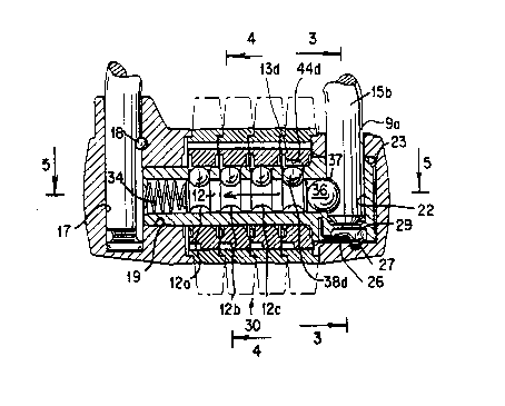
F$g. 1 is an exploded perspective view of
selected parts of the lock;
Fig. lA is also an exploded perspective view of
certain parts of the lock;
Fig. 2 is a partial elevational sectional view of
the lock;
. :

WO91/11580 2 0 4 7 6 7 6 PCT/~iSgl/00634
Fig. 3 is a sectional view along line 1-3 of Fig
2;
Fig. 4 is a sectional view along line 4-4 of Fig.
2;
Fig. 5 is a selected view along line 5-5 of Fig.
2; and
Fig. 6 is bottom perspective of the lock cap.
Descr ption of the Preferred Embodiment
In Figs. 1 and lA, lock 10 includes fixed body
portion 8, removable cap end 9, lock shaft body 11, lock
shaft 12, clutches 13 a-d and, combination wheels 16a-d, and
5U-shaped shackle 15 with shackle legs 15a, 15b. Shaft body
11 includes shaft portion lla having both holes 25a-d and
head llb. Lock shaft body 11 is permanently fixed to body
portion 8 using a pin or other suitable means.
Fixed body portion 8 in turn includes shackle
sleeve opening 17, shackle leg retaining pin 18 and shaft
body recess 19 (Fig. 2). Removable end cap 9 has shackle
cap recess ga and lock shaft body head llb includes shaft
recess sleev- 22 aligned to receive l~eg 15b Caps also has
25 recess 23 to house head llb.
Removable end cap 9 is held in lock position by
shac~le leg 15b; however, when leg 15b is moved out of head
llb and cap 9, cap 9 is readily removable by the exertion o.
force to cause cap 9 to be urged away from shaft body head
llb causing spring 26 to move out of lock cap cavity 27 into
head dwell recess 29.
. ' ~ .

WO91/11580 _3 2 0 ~ ~ 6 7 ~ PCT/~S91/00634
Lock 10 further includes locking mechanism 30 in
which shaft 12, housed in shaft body recess 19 of shaft body
portion lla, is urged to the right (Fig. 2) by coil spring
3~ causing large shackle lock ball 36 to engage shackle
notch 37 of shackle leg 15b. Shaft 12 includes four (4)
annular shackle depressions 12a-d for accommodating small
shaft lock balls 38a-d. Lock balls 38a-d are captured in
depression 12a-d and restrained by clutches 13a-d. Each
clutch 13a-d includes a bali clutch pocket 44a-d which
permits shaft lock balIs 38a-d to be moved out of shaft
10 grooves 12a-d to permit spring 34 to be compressed as
shackle leg 15b is pulled upwardly camming ball 36 to the
left (see arrow in Fig. 2) to unlock the lock. Fig. 2 shows
the clutches 13a-d positioned with clutches 13a-c in
positions in which balls 38a-c can not move upwardly out of
grooves 12a-c while clutch 13d'is turned so that clutch
pocket 44d permits ball 38d to move upwardly upon laterally
movement of shaft 12. Clutches 13a-d are moved to selected
positions by combination wheels 16a-b which are engageable
as clutch pro~ections 47a-d enter wheel recesses 48.
20 Clutches 16a-d also carry thumb pieces 51a-d.
Once the combination wheels 16a-d are aligned to
permit balls 38a-d to be moved upwardly, a pull on shackle
15 cau~es shackle leg 51a to move upwardly camming ball 36
25 to the left (Fig. 2) to release leg 15b. As leg 15b is
moved upwardly out of cap recess 9a and,head recess 22, cap
end 9 is free to be disassembled by applying sufficient
force to cause spring 27 to move into dwell recess 29 and
release cap 9.
,
once cap end 9 is removed, combination wheels
16a-d can be removed laterally and replaced with each of the
sets'of projections 47a-d moved into a number of wheel
35recesses 48 on clutches 13a.-d to create a new combination.

Representative Drawing
A single figure which represents the drawing illustrating the invention.
Administrative Status

2024-08-01:As part of the Next Generation Patents (NGP) transition, the Canadian Patents Database (CPD) now contains a more detailed Event History, which replicates the Event Log of our new back-office solution.

Please note that "Inactive:" events refers to events no longer in use in our new back-office solution.

For a clearer understanding of the status of the application/patent presented on this page, the site Disclaimer , as well as the definitions for Patent , Event History , Maintenance Fee  and Payment History  should be consulted.

Event History

Description Date
Inactive: IPC from MCD 2006-03-11
Time Limit for Reversal Expired 1998-01-30
Application Not Reinstated by Deadline 1998-01-30
Deemed Abandoned - Failure to Respond to Maintenance Fee Notice 1997-01-30
Application Published (Open to Public Inspection) 1991-08-01

Abandonment History

Abandonment Date Reason Reinstatement Date
1997-01-30
Owners on Record

Note: Records showing the ownership history in alphabetical order.

Current Owners on Record
MASTER LOCK COMPANY
Past Owners on Record
KENNETH N., SR. GRANDY
Past Owners that do not appear in the "Owners on Record" listing will appear in other documentation within the application.
Documents

To view selected files, please enter reCAPTCHA code :


To view images, click a link in the Document Description column. To download the documents, select one or more checkboxes in the first column and then click the "Download Selected in PDF format (Zip Archive)" or the "Download Selected as Single PDF" button.

List of published and non-published patent-specific documents on the CPD .

If you have any difficulty accessing content, you can call the Client Service Centre at 1-866-997-1936 or send them an e-mail at CIPO Client Service Centre.


Document
Description 
Date
(yyyy-mm-dd) 
Number of pages   Size of Image (KB) 
Abstract 1991-08-01 1 10
Drawings 1991-08-01 3 85
Cover Page 1991-08-01 1 13
Claims 1991-08-01 1 26
Descriptions 1991-08-01 3 91
Representative drawing 1999-08-23 1 19
Reminder - Request for Examination 1997-09-30 1 117
Fees 1996-01-10 1 28
Fees 1995-01-09 1 33
Fees 1994-01-24 1 28
Fees 1992-11-24 1 25