Sélection de la langue

Search

Sommaire du brevet 2047676 

Énoncé de désistement de responsabilité concernant l'information provenant de tiers

Une partie des informations de ce site Web a été fournie par des sources externes. Le gouvernement du Canada n'assume aucune responsabilité concernant la précision, l'actualité ou la fiabilité des informations fournies par les sources externes. Les utilisateurs qui désirent employer cette information devraient consulter directement la source des informations. Le contenu fourni par les sources externes n'est pas assujetti aux exigences sur les langues officielles, la protection des renseignements personnels et l'accessibilité.

Disponibilité de l'Abrégé et des Revendications

L'apparition de différences dans le texte et l'image des Revendications et de l'Abrégé dépend du moment auquel le document est publié. Les textes des Revendications et de l'Abrégé sont affichés :

  • lorsque la demande peut être examinée par le public;
  • lorsque le brevet est émis (délivrance).
(12) Demande de brevet: (11) CA 2047676
(54) Titre français: CADENAS A ARCEAU A COMBINAISON TOURNANTE MODIFIABLE
(54) Titre anglais: CHANGEABLE ROTARY COMBINATION SHACKLE LOCK
Statut: Réputée abandonnée et au-delà du délai pour le rétablissement - en attente de la réponse à l’avis de communication rejetée
Données bibliographiques
(51) Classification internationale des brevets (CIB):
  • E05B 37/06 (2006.01)
  • E05B 37/02 (2006.01)
(72) Inventeurs :
  • GRANDY, KENNETH N., SR. (Etats-Unis d'Amérique)
(73) Titulaires :
  • MASTER LOCK COMPANY
(71) Demandeurs :
  • MASTER LOCK COMPANY (Etats-Unis d'Amérique)
(74) Agent: OSLER, HOSKIN & HARCOURT LLP
(74) Co-agent:
(45) Délivré:
(86) Date de dépôt PCT: 1991-01-30
(87) Mise à la disponibilité du public: 1991-08-01
Licence disponible: S.O.
Cédé au domaine public: S.O.
(25) Langue des documents déposés: Anglais

Traité de coopération en matière de brevets (PCT): Oui
(86) Numéro de la demande PCT: PCT/US1991/000634
(87) Numéro de publication internationale PCT: WO 1991011580
(85) Entrée nationale: 1991-09-06

(30) Données de priorité de la demande:
Numéro de la demande Pays / territoire Date
472,693 (Etats-Unis d'Amérique) 1990-01-31

Abrégés

Abrégé anglais


ABSTRACT OF THE DISCLOSURE
A shackle leg changeable combination lock
including clutches and combination wheels slidable to
position therein for positive engagement in which the
combination wheels are axially restrained in position by a
removable cap held by a detent means. The cap is removable
when a shackle leg is moved upwardly to an unlock position
and the cap detent means is overcome by application of
force.

Revendications

Note : Les revendications sont présentées dans la langue officielle dans laquelle elles ont été soumises.


WO91/11580 -4- PCT/US91/00634
Claims:
1. A changeable combination U-shaped shackle
lock in which the shackle has two legs and further has
clutches and combination wheels comprising
a) a fixed body having a shaft means and
head means for receiving and holding a
first shackle leg in the fixed body for
limited movement therein;
b) the shaft means having a hollow shaft
recess extending therethrough;
c) a reciprocal shaft positioned in the
hollow shaft recess, which shaft is
normally urged toward the second leg
located in the head means;
d) a ball between the reciprocal shaft and
second leg to lock the second leg; and
e) a removable spring-loaded cap
positionable on the head means
whereby the head means, cap and second leg engage when the
lock is locked and second leg and cap do not engage when the
lock is unlocked.
2. The lock of claim 1 in which the shaft has
grooves, the shaft means includes holes and the clutches
have pockets, all for accommodating lock balls.
3. The lock of claim 1 in which the removable
cap is held on the head means by a spring detent means which
detent means is releasable when the lock is in its unlock
position and the second leg removed from the head means and
the cap.

Description

Note : Les descriptions sont présentées dans la langue officielle dans laquelle elles ont été soumises.

WO9t/1158~ ~ 2 0 4 ~ 6 7 ~ PCT/~S91/~6~
CHANGEABLE ROTARY CoMBINATIoN SHACKLE LOCK
Backqround of the Invention
Cable or chain combination locks of the type
having means for setting or changing the combination have
been known (U.S. Patent Nos. 4,445,348 and 4,615,191).
Other com~ination locks have included mechanisms described
in U.S. Patent Nos. 1,706,994; 1,898,947; 4,354,365;
4,441,346: and 4,831,860.
Summarv Of The Invention
Broadly, the present invention includes a shackle
combination lock that is readily partially disassembled when
the shackle is pulled to the open position to permit change
of the combination. A cap end is removable by causing the
depression of a spring-loaded clasp permitting the
15combination wheels to be removed from the clutches and
replaced in a selected position to attain the desired new
combination.
It is a feature of the lock that the removable
20cap is securely held by the lock shackle in the lock
position and readily removable when the shackle is in the
unlock position.
Brief Description Or the Drawinqs
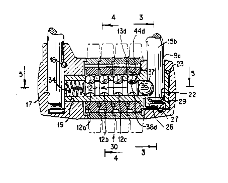
F$g. 1 is an exploded perspective view of
selected parts of the lock;
Fig. lA is also an exploded perspective view of
certain parts of the lock;
Fig. 2 is a partial elevational sectional view of
the lock;
. :

WO91/11580 2 0 4 7 6 7 6 PCT/~iSgl/00634
Fig. 3 is a sectional view along line 1-3 of Fig
2;
Fig. 4 is a sectional view along line 4-4 of Fig.
2;
Fig. 5 is a selected view along line 5-5 of Fig.
2; and
Fig. 6 is bottom perspective of the lock cap.
Descr ption of the Preferred Embodiment
In Figs. 1 and lA, lock 10 includes fixed body
portion 8, removable cap end 9, lock shaft body 11, lock
shaft 12, clutches 13 a-d and, combination wheels 16a-d, and
5U-shaped shackle 15 with shackle legs 15a, 15b. Shaft body
11 includes shaft portion lla having both holes 25a-d and
head llb. Lock shaft body 11 is permanently fixed to body
portion 8 using a pin or other suitable means.
Fixed body portion 8 in turn includes shackle
sleeve opening 17, shackle leg retaining pin 18 and shaft
body recess 19 (Fig. 2). Removable end cap 9 has shackle
cap recess ga and lock shaft body head llb includes shaft
recess sleev- 22 aligned to receive l~eg 15b Caps also has
25 recess 23 to house head llb.
Removable end cap 9 is held in lock position by
shac~le leg 15b; however, when leg 15b is moved out of head
llb and cap 9, cap 9 is readily removable by the exertion o.
force to cause cap 9 to be urged away from shaft body head
llb causing spring 26 to move out of lock cap cavity 27 into
head dwell recess 29.
. ' ~ .

WO91/11580 _3 2 0 ~ ~ 6 7 ~ PCT/~S91/00634
Lock 10 further includes locking mechanism 30 in
which shaft 12, housed in shaft body recess 19 of shaft body
portion lla, is urged to the right (Fig. 2) by coil spring
3~ causing large shackle lock ball 36 to engage shackle
notch 37 of shackle leg 15b. Shaft 12 includes four (4)
annular shackle depressions 12a-d for accommodating small
shaft lock balls 38a-d. Lock balls 38a-d are captured in
depression 12a-d and restrained by clutches 13a-d. Each
clutch 13a-d includes a bali clutch pocket 44a-d which
permits shaft lock balIs 38a-d to be moved out of shaft
10 grooves 12a-d to permit spring 34 to be compressed as
shackle leg 15b is pulled upwardly camming ball 36 to the
left (see arrow in Fig. 2) to unlock the lock. Fig. 2 shows
the clutches 13a-d positioned with clutches 13a-c in
positions in which balls 38a-c can not move upwardly out of
grooves 12a-c while clutch 13d'is turned so that clutch
pocket 44d permits ball 38d to move upwardly upon laterally
movement of shaft 12. Clutches 13a-d are moved to selected
positions by combination wheels 16a-b which are engageable
as clutch pro~ections 47a-d enter wheel recesses 48.
20 Clutches 16a-d also carry thumb pieces 51a-d.
Once the combination wheels 16a-d are aligned to
permit balls 38a-d to be moved upwardly, a pull on shackle
15 cau~es shackle leg 51a to move upwardly camming ball 36
25 to the left (Fig. 2) to release leg 15b. As leg 15b is
moved upwardly out of cap recess 9a and,head recess 22, cap
end 9 is free to be disassembled by applying sufficient
force to cause spring 27 to move into dwell recess 29 and
release cap 9.
,
once cap end 9 is removed, combination wheels
16a-d can be removed laterally and replaced with each of the
sets'of projections 47a-d moved into a number of wheel
35recesses 48 on clutches 13a.-d to create a new combination.

Dessin représentatif
Une figure unique qui représente un dessin illustrant l'invention.
États administratifs

2024-08-01 : Dans le cadre de la transition vers les Brevets de nouvelle génération (BNG), la base de données sur les brevets canadiens (BDBC) contient désormais un Historique d'événement plus détaillé, qui reproduit le Journal des événements de notre nouvelle solution interne.

Veuillez noter que les événements débutant par « Inactive : » se réfèrent à des événements qui ne sont plus utilisés dans notre nouvelle solution interne.

Pour une meilleure compréhension de l'état de la demande ou brevet qui figure sur cette page, la rubrique Mise en garde , et les descriptions de Brevet , Historique d'événement , Taxes périodiques et Historique des paiements devraient être consultées.

Historique d'événement

Description Date
Inactive : CIB de MCD 2006-03-11
Le délai pour l'annulation est expiré 1998-01-30
Demande non rétablie avant l'échéance 1998-01-30
Réputée abandonnée - omission de répondre à un avis sur les taxes pour le maintien en état 1997-01-30
Demande publiée (accessible au public) 1991-08-01

Historique d'abandonnement

Date d'abandonnement Raison Date de rétablissement
1997-01-30
Titulaires au dossier

Les titulaires actuels et antérieures au dossier sont affichés en ordre alphabétique.

Titulaires actuels au dossier
MASTER LOCK COMPANY
Titulaires antérieures au dossier
KENNETH N., SR. GRANDY
Les propriétaires antérieurs qui ne figurent pas dans la liste des « Propriétaires au dossier » apparaîtront dans d'autres documents au dossier.
Documents

Pour visionner les fichiers sélectionnés, entrer le code reCAPTCHA :


Pour visualiser une image, cliquer sur un lien dans la colonne description du document. Pour télécharger l'image (les images), cliquer l'une ou plusieurs cases à cocher dans la première colonne et ensuite cliquer sur le bouton "Télécharger sélection en format PDF (archive Zip)" ou le bouton "Télécharger sélection (en un fichier PDF fusionné)".

Liste des documents de brevet publiés et non publiés sur la BDBC .

Si vous avez des difficultés à accéder au contenu, veuillez communiquer avec le Centre de services à la clientèle au 1-866-997-1936, ou envoyer un courriel au Centre de service à la clientèle de l'OPIC.


Description du
Document 
Date
(aaaa-mm-jj) 
Nombre de pages   Taille de l'image (Ko) 
Abrégé 1991-08-01 1 10
Dessins 1991-08-01 3 85
Page couverture 1991-08-01 1 13
Revendications 1991-08-01 1 26
Description 1991-08-01 3 91
Dessin représentatif 1999-08-23 1 19
Rappel - requête d'examen 1997-09-30 1 117
Taxes 1996-01-10 1 28
Taxes 1995-01-09 1 33
Taxes 1994-01-24 1 28
Taxes 1992-11-24 1 25