Note: Descriptions are shown in the official language in which they were submitted.
20 47 8~0
Background of the Invention
The present invention relates to improvements in
spray guns, and in particular to a spray gun for
spraying two liquid reactants.
One type of spray gun for plural component
a
materials is disclosed in U.S. patent No. 3,366,337 to
Brooks et al. That spray gun is of the internal mix
airless type and means are provided for intimately
mixing two liquid reactants immediately prior to
spraying the same. This is accomplished by impinging
streams of the reactants against each other under
pressure from opposed directions into the rearward end
of a relatively large mixing chamber within the gun,
whereby the reactants are mixed within the chamber and
then discharged through an airless outlet orifice at a
forward end of the chamber.
At the end of a spraying operation with the spray
gun of said patent No. 3,366,337, mixed reactants within
the chamber must be quickly removed before completion of
the reaction and formation of a blockage in the gun.
Means are therefore provided for introducing a stream of
solvent into the rearward end of the chamber after the
gun has been operated, so that the chamber and outlet
orifice can be cleaned of residual material to enable
further spraying operations. Disadvantages of the
technique are that a separate container is usually
required to collect the discharge during cleaning, it
can happen that solvent contacts and mars a finished
product, the use of solvent adds cost to the operation
and it is undesirable for solvent to be sprayed into the
air. In addition, cleaning the chamber with solvent
often is less than thorough, with the result that the
-2-
20 47 860
gun must be disassembled to remove hardened material,
and whenever the gun is not going to be used for a
period of time, customary practice contemplates that it
be soaked in solvent to remove mixed reactants. Also,
with some types of modern day materials, mere
impingement together of reactants in a chamber does not
provide satisfactory mixing.
One use for plural component spray guns is in
fiberglass spraying systems in which resin and catalyst
are brought together in a spray into which fiberglass
particles are introduced for being wetted and carried to
a workpiece. Fiberglass spray guns, often referred to
as FRP (fiberglass reinforced plastics) spray guns, may
be of either the internal or external mix type. As
above discussed, internal mixing of coreactive liquid
components such as catalyst and resin requires time
consuming and extensive cleaning of the spray gun
periodically and after each use. External mixing of the
components, on the other hand, decreases the amount of
cleaning required. With an external mix spray gun,
catalyst and resin streams are emitted from separate
nozzles and usually are atomized prior to being mixed
together. Because the catalyst and resin are mixed
externally of the spray gun, there are no mixed
reactants within the gun which must be removed prior to
completion of the reaction to prevent a blockage in the
gun.
Some major concerns in designing and operating
external mix FRP spray guns include providing a
thoroughly mixed spray, a sufficiently high utilization
of catalyst and low emissions of catalyst fumes. Unless
the resin and catalyst are thoroughly mixed the
-3-
-_ - 20 47 860
fiberglass curing rate will not be uniform and there will be
a lack of uniformity between workpieces. However, it is
difficult to properly mix atomized sprays of resin and
catalyst. Also, because the catalyst is atomized prior to
mixing, a considerable amount of the catalyst spray does not
become admixed with the resin spray and there is a decreased
utilization of catalyst and an increase in catalyst fumes.
Typical prior spray guns having the aforementioned
disadvantages are shown in U.S. Patent no. 4,618,098 issued
October 21, 1986 to Hedger et al. and in British Patent No.
735,983 to Dehn published November 10, 1976. In each, resin
and catalyst are both atomized prior to being mixed, in
consequence of which there is less than thorough mixing of the
resin and catalyst, low catalyst utilization and relatively
high emissions of catalyst fumes.
Obiects of the Invention
An object of the present is to provide an improved
plural component external mix spray gun in which a first
liquid component such as resin is emitted from an airless tip
and a second liquid component such as catalyst is directed in
an unatomized stream into the first liquid component adjacent
to the point of its emission from the airless tip.
Another obj ect is to provide such a spray gun of the
air-assisted/airless type.
PG:jJ
- 4 -
2047860
A further object is to provide such a spray gun in which
an injector nozzle for the second liquid component is built into an
ear of an air cap for the spray gun and in which the air cap is
keyed to the airless tip to maintain the positional relationship
between the injector nozzle and the airless tip.
Yet another object is to provide such a spray gun for use
in spraying fiber reinforced plastics.
Summary of the Invention
In accordance with the present invention there is provided
a plural component spraying device comprising: a fluid tip having
an orifice; means for pressure delivery of a first liquid to the
fluid tip for emission from the orifice in a dense, narrow and
expanding film of the first liquid that breaks up downstream from
the fluid tip into an atomized spray independent of interaction of
air therewith; an injector nozzle having an orifice; and means for
delivering a second liquid to the injector nozzle for emission from
the injector nozzle orifice in an unatomized stream that impinges
against the first liquid downstream from the fluid tip, at a point
where the first liquid is still a dense and narrow film that has not
yet atomized into a spray, to admix the liquids.
In a contemplated embodiment, the spraying apparatus
comprises a spray gun body on which is mounted a fluid nozzle means
having an elongate fluid orifice. Means are included for pressure
delivery of a first liquid to the fluid nozzle means for emission
-5-
,~ 20 4~ aso
from its orifice in a fan-shaped expanding and atomized spray, and
an air cap means is mounted on the gun body around the fluid nozzle
means and has at least two air orifices to opposite sides of the
fluid nozzle means. An injector nozzle means having a fluid orifice
is carried by the air cap means, and means are provided for pressure
delivery of a second liquid to the injector nozzle means for
emission from its orifice in an unatomized stream that impinges
against the first liquid adjacent to and downstream from the fluid
nozzle means to admix the liquids. Also included are means for
l0 pressure delivery of air to the air cap means air orifices for
emission from the air orifices and impingement against opposite
sides of the first and second liquids adjacent to and downstream
from the fluid nozzle means to assist in breaking up the first and
second liquids into an atomized spray.
The invention also contemplates a method of spraying a
plural component material, comprising the steps of: delivering a
first liquid under pressure to a fluid tip having an orifice;
emitting the first liquid from the fluid tip orifice in a dense,
narrow and expanding film that breaks up downstream from the orifice
into an atomized spray independent of interaction of air therewith;
delivering a second liquid to an injector nozzle having an orifice;
and emitting the second liquid from the injector nozzle orifice in
an unatomized stream directed against the first liquid downstream
-6-
204780
from the fluid tip, at a point where the first liquid is still a
dense and narrow film that has not yet atomized into a spray, to
admix the liquids.
A preferred practice of the method includes the steps of
delivering a first liquid under pressure to a fluid nozzle having an
elongate fluid orifice, emitting the first liquid from the elongate
orifice in a fan-shaped expanding and atomizing spray, and
delivering air under pressure to an air cap positioned around the
fluid nozzle and having at least two air outlet orifices to opposite
sides of the fluid nozzle. Also provided are the steps of
delivering a second liquid to a fluid outlet orifice of an injector
nozzle on the air cap, emitting the second liquid from the injector
nozzle orifice in an unatomized stream directed against the first
liquid adjacent to and downstream from the fluid nozzle to admix the
liquids, and emitting air from the air cap air outlet orifices and
impinging the air
-6a-
Zo4~8so
against the first and second liquids adjacent to and
downstream from the fluid nozzle to assist in atomizing
the liquids.
The foregoing and other objects, advantages and
features of the invention will become apparent upon a
consideration of the following detailed description,
when taken in conjunction with the accompanying
drawings.
Brief Description of the Drawings
Fig. 1 is a side elevation view, partly in cross
section, illustrating a plural component external mix
spray gun according to the teachings of the present
invention;
Fig. 2 is a top plan view, partly in cross section,
illustrating additional features of the spray gun, and
Fig. 3 is a front elevation view of the spray gun.
Detailed Description
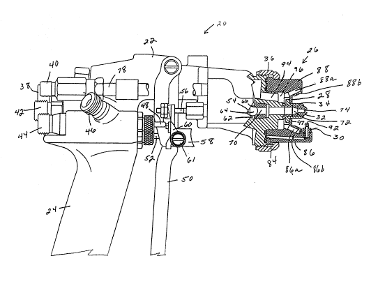
A plural component external mix air-
assisted/airless spray coating apparatus is shown in the
drawings as a hand held spray gun, indicated generally
at 20. The spray gun is for spraying fiberglass and is
often referred to in the trade as an FRP (fiberglass '
reinforced plastics) spray gun. It includes a gun body
22 having a rearward handle 24 grippable by an operator
to hold and manipulate the gun. At its forward end the
gun body carries a spray head assembly, indicated
generally at 26. The spray head assembly includes an
air cap 28 which has or in which is mounted a catalyst
injector nozzle 30. The spray head assembly also
includes an airless spray tip 32 carried by a tip holder
20 47860
34 that extends through and is surrounded by the air
cap. A retaining ring 36 attaches the spray head
assembly to the front of the gun body.
The FRP spray gun 20 emits a spray of resin and '
catalyst into which reinforcing fiberglass particles may
be introduced for being wetted and carried by the spray
to a workpiece. The gun body 22 has at its rearward end
a resin inlet 38, a catalyst inlet 40 and an atomizing
air inlet 42. Although not shown, an air powered
fiberglass chopper would normally be mounted atop the
gun body. To deliver air to the chopper for powering
the same, the gun body also has a chopper air inlet 44,
a chopper air outlet 46 that connects to the chopper and
a chopper air valve 48 for controlling a flow of air
from the inlet to the outlet.
A gun trigger 50 is pivotally connected to the
spray gun body 22 for actuating an atomizing air valve
52, a resin valve 54 and a catalyst valve 56. The gun
trigger is movable between a forward position where the
atomizing air, resin and catalyst valves are closed and
a rearward position toward the gun handle 24 to open the
atomizing air, resin and catalyst valves. A chopper
. trigger 58 is pivotally connected to the gun body and is
moved rearwardly by the gun trigger to open the chopper
air valve 48 to operate the chopper. The chopper
trigger may also be manually moved rearwardly
independently.of the gun trigger to open the chopper air
valve while the atomizing air, resin and catalyst valves
remain closed. The chopper trigger has a valve actuator
60 pivotally mounted at 61 which may be rotated
clockwise through 90° from its position shown in Fig. 1
_g_
CA 02047860 1999-11-O1
so that upon rearward movement of the chopper trigger the
chopper air valve is not engaged and opened. The FRP spray gun
20 can therefore selectively be operated to introduce
fiberglass particles into a spray of resin and catalyst, to
spray resin and catalyst without introducing fiberglass
particles therein or to project fiberglass particles from the
gun without simultaneously emitting a spray of resin and
catalyst.
The resin valve 54 comprises an elongate stem extending
forwardly from the gun trigger 50 into a resin passage 62 in
the gun body 22. The resin passage communicates with the resin
inlet 38 through a tube 63 (Fig. 2) and receives resin supplied
to the inlet at a pressure on the order of about 300-1000 psi.
A ball 64 at the forward end of the stem normally is urged
against a seat 66 in a seat holder 68 through which a passage
70 extends. The :ball is moved off of the seat upon retraction
of the stem by the gun trigger to establish a path for a flow
of resin from the passage 62, through the passage 70 and a
passage 72 in the tip holder 34, to and through an elliptical
orifice 74 in the spray tip 32. The orifice is configured such
that resin emitted from it is in the form of a coherent and
unstable fan-shaped liquid film that breaks up into an atomized
spray at its forward edge.
The catalyst valve 56 comprises a needle valve stem
extending forward:ly from the gun trigger 50 into a catalyst
passage 76 (Fig. 2). The catalyst passage communicates through
_ g_
CA 02047860 1999-11-O1
a tube 78 with the catalyst inlet 40 for receiving catalyst
pressure delivered to the inlet. A conical forward end 80 of
the valve stem normally is urged against a seat in a seat
holder 82 at a forward end of the catalyst passage. A passage
through the seat holder communicates with a circular channel 84
in the forward end of the gun body. The rearward end of the
air cap 28 abuts the forward end of the gun body and extends
across the channel, and a pair of O-rings inwardly and
outwardly of the channel provide a seal between the gun body
and air cap. The air cap has a pair of diametrically opposed
ears or horns 86 and 88 and a catalyst delivery passage 90
extends through the ear 86 between the channel 84 and the
catalyst injector nozzle 30. When the catalyst valve 56 is
retracted from its seat it establishes a path for a flow of
catalyst from the passage 76, through the seat holder 82 into
the channel 84 anal from the channel into and through the air
cap passage 90 to the catalyst injector nozzle 30 for emission
from a circular catalyst outlet orifice 92 in an unatomized
cylindrical stream. The unatomized stream of catalyst is
directed into the resin substantially immediately adjacent to
the forward end of the airless spray tip 32 and downstream from
the point of emission of the resin from the orifice 74 in the
tip.
The atomizing air valve 52 (Fig. 1) is opened upon
retraction of the gun trigger 50 to establish a path between
the atomizing air inlet 42 and a gun body passage 94 that leads
-10-
CA 02047860 1999-11-O1
to an annular chamber 96 defined between the forward end of the
gun body 22, the air cap 28 and the tip holder 34. Passages
86a and 88a in the air cap horns 86 and 88 extend between the
chamber and air outlet orifices 86b and 88b in the horns.
The tip holder extends forwardly through an opening in a
front face 97 of the air cap 28 and is keyed to the air cap by
means of flats 98 (Fig. 3) formed on opposite sides of the tip
holder and air cap opening. The tip holder and the airless tip
are therefore brought into and maintained in fixed positional
relationship with respect to the air cap, whereby the
elliptical outlet: orifice 74 in the airless tip 32 and the
catalyst injector nozzle 30 also are maintained in fixed
orientation with respect to each other. The orientation of the
catalyst injector nozzle with respect to the elliptical orifice
is such that a longitudinal axis of a catalyst injector nozzle
passage that leads to the circular catalyst outlet orifice 92
extends substantially immediately adjacent to and downstream
from the forwardmost end of the airless spray tip 32 and
perpendicular to the major axis of the elliptical orifice.
This orientation is maintained even when the spray head
assembly 26 is rotated to change the plane of the fan-shaped
spray, with the annular catalyst channel 84 and the annular air
chamber 96 (Fig.7_) providing for continuous connection of
catalyst and air to the spray head for all the rotational
orientations of the spray head on the gun body.
Considering operation of the FRP spray gun 20 in emitting
a spray of resin and catalyst, upon retraction of the gun
trigger 50 the atomizing air valve 52, the resin valve 54 and
the catalyst valve 56 are opened. Opening the resin valve
provides for a flow of resin to and through the elliptical
orifice 74 in the airless spray tip 32. The resin is delivered
to the orifice at. a pressure on the order of about 300-1000
psi, as a result of which it is emitted from the orifice in the
form of a fan-shaped unstable and coherent film of resin that
breaks up at its forward edge into an atomized spray.
-11-
~
20 47880
Because resin is supplied to the airless spray tip
32 at a relatively low pressure, the degree to which it
is atomized is less than desirable. The air-
assist/airless principle is therefore employed to '
enhance the degree of atomization. To that end, the air
cap outlet orifices 86b and 88a in the ai'r cap horns 86
and 88 are diametrically opposed and lie in a plane
extending perpendicular to the major axis of the
elliptical orifice 74, and emit jets of air that impact
against the resin adjacent where it exits the elliptical
orifice to impart additional energy to the resin and
cause it to break up into a more finely atomized fan-
shaped spray.
Opening the catalyst valve 56 upon retraction of
the gun trigger 50 causes catalyst to flow through the
catalyst injector nozzle 30 and out of its orifice 92 in
a cylindrical unatomized stream that impinges against
the resin emitted from the elliptical orifice 74 in the
airless spray tip 32. The cylindrical stream of
catalyst extends along the axis of the passage through
the catalyst injector nozzle, i.e., along an axis
passing substantially adjacent to and downstream from
the forwardmost end of the airless spray tip 32 and its
elliptical orifice 74, and extending perpendicular to
the major axis of the elliptical orifice. The circular
catalyst orifice may have a diameter on the order of
.010" and the .stream of catalyst emitted from the
orifice impinges against the resin stream substantially
adjacent to and downstream from its point of emission
from the elliptical orifice. At the point of
impingement the resin stream has not yet significantly
expanded and is still dense and narrow, in consequence
-12-
204~sso-
of which the catalyst is thoroughly mixed into the resin
and carried along with the resin and atomized into a fan-
shaped spray. The result is that catalyst utilization
approaches 100$ and evaporation of catalyst and emission '
of catalyst fumes is substantially eliminated.
Although not specifically mentioned in describing
operation of the FRP spray gun 20, it is understood that
the chopper (not shown) would normally be operated
during spraying to project fiberglass particles into the
admixed and atomized spray of resin and catalyst for
being wetted by and carried with the spray to a
workpiece.
While one embodiment of the invention has been
described in detail, various modifications and other
embodiments thereof may be devised by one skilled in the
art without departing from the spirit and scope of the
invention, as defined in the appended claims.
-13-