Language selection

Search

Patent 2047931 Summary

Third-party information liability

Some of the information on this Web page has been provided by external sources. The Government of Canada is not responsible for the accuracy, reliability or currency of the information supplied by external sources. Users wishing to rely upon this information should consult directly with the source of the information. Content provided by external sources is not subject to official languages, privacy and accessibility requirements.

Claims and Abstract availability

Any discrepancies in the text and image of the Claims and Abstract are due to differing posting times. Text of the Claims and Abstract are posted:

  • At the time the application is open to public inspection;
  • At the time of issue of the patent (grant).
(12) Patent Application: (11) CA 2047931
(54) English Title: PREFABRICATED UNIT BUILDING WALL
(54) French Title: PAROI EN ELEMENTS PREFABRIQUES
Status: Deemed Abandoned and Beyond the Period of Reinstatement - Pending Response to Notice of Disregarded Communication
Bibliographic Data
(51) International Patent Classification (IPC):
  • E04B 02/00 (2006.01)
  • E04B 01/10 (2006.01)
(72) Inventors :
  • WOLF, JOHANN (Austria)
  • WOLF, JOHANN (Austria)
(73) Owners :
  • JOHANN WOLF
  • JOHANN WOLF
(71) Applicants :
(74) Agent: BORDEN LADNER GERVAIS LLP
(74) Associate agent:
(45) Issued:
(22) Filed Date: 1991-07-25
(41) Open to Public Inspection: 1992-01-28
Examination requested: 1992-01-20
Availability of licence: N/A
Dedicated to the Public: N/A
(25) Language of filing: English

Patent Cooperation Treaty (PCT): No

(30) Application Priority Data:
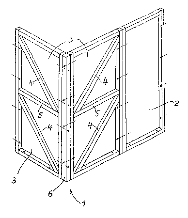
Application No. Country/Territory Date
A 1582/90 (Austria) 1990-07-27

Abstracts

English Abstract


ABSTRACT
PREFABRICATED UNIT BUILDING WALL
A wall consisting of corner units (1) and wall units
(2) where the corner units are frames (3) meeting at an angle,
and have oblique bracings (4) and cross braces (5) and are
connected with one another in the zone of the meeting angle by
corner posts (6) or the equivalent. The wall units (2) have
rectangular frames.


Claims

Note: Claims are shown in the official language in which they were submitted.


THE EMBODIMENTS OF THE INVENTION IN WHICH AN EXCLUSIVE PROPERTY
OR PRIVILEGE IS CLAIMED ARE DEFINED AS FOLLOWS:
1. Wall for a building composed of prefabricated wall
units having closed rectangular frames, and corner units joined
thereto, the corner units comprising braced and/or rigidified
frames meeting at an angle with respect to one another.
2. Wall according to claim 1, the corner units having
bracings extending obliquely downwardly toward the apex of the
meeting angle formed between their frames.
3. Wall according to claim 1 or 2, each corner unit
having a ratio of width to height of 1 : 2, each corner unit
frame being subdivided by a cross brace in the center of its
height, the bracing extending downwardly at 45°.
4. Wall according to claims 1, 2 or 3, the corner unit
frames consisting of wood and being joined together in a zone at
the apex of their meeting angle by a vertical corner post.
5. Wall according to claims 1, 2 or 3, the corner unit
frames being selected from steel and reinforced concrete and
being directly connected to one another.

6. Wall according to claims 1, 2, 3, 4 or 5, the corner
units being joined to the respective wall unit frames at
respective frame uprights and being connected at respective
horizontal plates with a concrete floor.
7. Wall according to claims 1, 2, 3, 4, 5 or 6, the
corner unit frames and the wall unit frames being lined with
enamaled metal panels on their outwardly facing sides.

Description

Note: Descriptions are shown in the official language in which they were submitted.


;~ t~ ~ ~ ;J r j ~
~ 1 ~
The invention relates to a wall oP pref~bricated wall
units with closed rectangular frames.
The conventional arrangements for buildings which can
be assembled from prefabricated units, for stiffening the
building comprise diagonal braces in the individual structural
units which absorb lateral wind load in the assembled
structure. The diagonal reinforcements interfere with a free
choice of arrangement for windows and doors, and appropriately
fashioned units are required. Introducing insulating material
into the units is made difficult by such bracing. The
acute-angled corners formed by the bracing can be filled with
insulating material only with difficulty and/or by taking
considerable time so that often cold-conducting bridges are
formed at these locations. Likewise, the subsequent window or
door placing is difficult. Manufacture of these units is
substantially more expensive because of these diagonal braces
with the many inclined cuts involved and, as a consequence of
the differently designed windows and door units, requires
variegated bracings and/or trimmed components.
DOS 2/143,579 discloses wall units and ceiling units
made of wood which are rigidified on the inside by
perpendicularly intersecting strips and are lined on the outside
with panels. Corner units have the same structure. This
building mode suffers from the drawbacks described above.
DOS 2,627,261 describes a wall construction composed

2,~
of joined profiled members~ especially of metal, where the
interstices are filled with concrete. This construction is very
expensive and uneconomic.
Wall and corner units consisting of beams are known
from W0 8~/05485. The strength of these units can be achieved
solely by the dimensioning o~ the individual components. This
entails considerable expenditure in material.
Herein described is a novel design of corner units,
with wall units having a simple structure which exhibit good
stiffness but do not limit the placing of doors, windows, and
the like.
In a wall of the type described the corner units have
braced and/or rigidified frames meeting at an angle to one
another.
Using such corner units, the wall unit~ can be
designed as simple, rectangular frames. The cornar and wall
units can have any desired design of outside or inside lining.
More particularly in accordance with the invention
there is provided a wall for a building composed of
prefakricated wall units having closed rectangular frames, and
corner units joined thereto, the corner units comprising braced
and/or rigidified frames meeting at an angle with respect to one
another.

2 ~ ~ ~ ' i ? j
Embodimen~s of ~he invention will now be described
with reference to the accompanying drawings, wherein:
Figure 1 shows a building in perspective view with a
roo~ indicated by dashed lines,
Figures 2 and 3 show two embodiments in plan view,
Figure 4 show~ in an oblique view, and
Figure 5 shows, in plan view, prefabricated components
embodying this invention made of wood.
Descri~tion of the Preferred Embod ments
As illustrated in Figures 2 and 3, for a pre~abricated
building, wall units 2 can be laid *lush with the outsides of
the corner units 1, or they can be placed offset toward the
inside, as in Figure 3, so as to particularly emphasize the
corners o~ the building. This method of construckion of~ers a
great variety of design possibilities and great adaptation to
the prevailing purpose of use ~or the building.
For example, buildings for commercial purposes can be
lined on the outer walls with shaped aluminum panels, and the
corner units 1 can be lined with enameled metal sheets of any
desired color. For residential purposes, mixed designs can be
executed, some with wall units placed flush and some offset
toward the insid2 (Figure 3).
Further, concrete corner units 1, or corner units 1
lined or faced with enameled metal panel~ give additional design
. '
' ` '
.

i(s~J~j
possibilities in conjunction with wall units 2 which are faced
with wood.
An important criterion for a rugged corner design
which is to withstand the shear caused by wind load is that the
corner units l consist of angularly arranged frames 3, as
illustrated in Figure 4. The bracings 4 of these frames extend
obliquely downwardly toward the apex of the angle formed by the
frames 3. These bracings transmit the shear toward the floor.
Each of the two frames 3 is subdivided in this arrangement by a
cross brace 5. With a ratiQ of width to height for the frames 3
of 1 : 2, and with a cross brace 5 located in the center of the
height dimension, two respective square component frames are
obtained, and the bracings 4 extend downwards at 45.
Where a corner unit 1 is made of wood, the two frames
3 are joined at a corner post 6, most preferably by screws or
bolts. The wall units 2 here are likewise made of wooden frames
and are preferably joined at their respective uprights to the
respective frame 3 by means of screws or bolts. The frames 3
and the wall units 2 have a uniform width, for example of
llO cm. All of the units are preferably connected at their
bottom plates by screws or bolts to the floor, for example a
concrete floor.
Corner units 1 of steel or rein~orced concrete have
the same structure as can be seen from Figure 4 showing the
wooden construction. The only difference is that the frames 3
are joined directly at the apex of the meeting angle, i.e.
without a specific corner post member.

Representative Drawing
A single figure which represents the drawing illustrating the invention.
Administrative Status

2024-08-01:As part of the Next Generation Patents (NGP) transition, the Canadian Patents Database (CPD) now contains a more detailed Event History, which replicates the Event Log of our new back-office solution.

Please note that "Inactive:" events refers to events no longer in use in our new back-office solution.

For a clearer understanding of the status of the application/patent presented on this page, the site Disclaimer , as well as the definitions for Patent , Event History , Maintenance Fee  and Payment History  should be consulted.

Event History

Description Date
Inactive: IPC from MCD 2006-03-11
Time Limit for Reversal Expired 1994-01-25
Application Not Reinstated by Deadline 1994-01-25
Inactive: Adhoc Request Documented 1993-07-26
Deemed Abandoned - Failure to Respond to Maintenance Fee Notice 1993-07-26
Application Published (Open to Public Inspection) 1992-01-28
All Requirements for Examination Determined Compliant 1992-01-20
Request for Examination Requirements Determined Compliant 1992-01-20

Abandonment History

Abandonment Date Reason Reinstatement Date
1993-07-26
Owners on Record

Note: Records showing the ownership history in alphabetical order.

Current Owners on Record
JOHANN WOLF
JOHANN WOLF
Past Owners on Record
None
Past Owners that do not appear in the "Owners on Record" listing will appear in other documentation within the application.
Documents

To view selected files, please enter reCAPTCHA code :


To view images, click a link in the Document Description column (Temporarily unavailable). To download the documents, select one or more checkboxes in the first column and then click the "Download Selected in PDF format (Zip Archive)" or the "Download Selected as Single PDF" button.

List of published and non-published patent-specific documents on the CPD .

If you have any difficulty accessing content, you can call the Client Service Centre at 1-866-997-1936 or send them an e-mail at CIPO Client Service Centre.

({010=All Documents, 020=As Filed, 030=As Open to Public Inspection, 040=At Issuance, 050=Examination, 060=Incoming Correspondence, 070=Miscellaneous, 080=Outgoing Correspondence, 090=Payment})


Document
Description 
Date
(yyyy-mm-dd) 
Number of pages   Size of Image (KB) 
Claims 1992-01-27 2 39
Abstract 1992-01-27 1 12
Drawings 1992-01-27 2 43
Descriptions 1992-01-27 4 142
Representative drawing 1999-07-05 1 19
Prosecution correspondence 1992-01-19 2 28
Courtesy - Office Letter 1992-03-03 1 44